Proof of concept video below. See Project Logs section for updates.
Hi-Fi Digital Audio from the Echo Dot
Hacking a digital audio output (i2s and/or optical) onto an Amazon Echo Dot V2
Hacking a digital audio output (i2s and/or optical) onto an Amazon Echo Dot V2
To make the experience fit your profile, pick a username and tell us what interests you.
We found and based on your interests.
Proof of concept video below. See Project Logs section for updates.
Small update (still working on this!!):
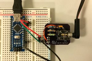
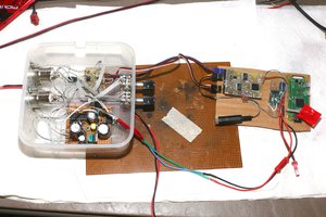
Since the last update a few things have happened. I ordered the sainsmart dac based on the pcm5122 as mentioned previously, and (I think) proceeded to kill it. I have a new 5122 chip on the way. In the meantime, I have redone the i2s lines to the pcm5122, beefed up the power supply a bit with a little LC circuit made from parts laying around, and put it all inside the case (sans internal speaker). Even this little 5102 dac blows the stock dac out of the water... For less than five bucks! Will be very interested to see how the 5122 with vastly better power supply and analog components will do. The change will be small for sure, but maybe noticeable. We'll see if it's worth 5x the price of the little 5102 board.
Also ordered a WM8804 transceiver board, as the eventual goal is to get a digital signal out to a receiver or dedicated dac. It will be a little trickier as it requires a mclk signal, and I haven't yet figured out exactly what frequencies the Echo's various clocks are at. (If anyone has a decent scope and wants to poke around in their echo, let me know!)
A few photos:
I took the leap! Today I removed the TI DAC3203 IC (datasheet here) from the Echo's motherboard and broke out the I2S lines to a cheap eBay PCM5102A DAC (datasheet here) board. Aaaaand after a little fiddling with the DAC... success! It works beautifully. Demo video below.
To-Do:
- Try out a couple other better DACs such as the Sainsmart HI-FI DAC meant for a Raspberry Pi
- Test implementation of an I2S to S/PDIF conversion IC (this one) to hook the Echo Dot up to a digital home theater receiver or optical input DAC.
- Re-instate the Echo's internal speaker, and somehow make it less clunky to switch between using the internal speaker and the audio output. I'd love to be able to somehow detect the status of the amplifier (hooked up/powered on or off) and switch the outputs with a microcontroller, but it seems like the best solution as of now is to voice-control the switch using an esp8266 configured as an alexa "smart home" device. Looking for suggestions here.
- manufacture a board to add a digital output, and 3D-print a larger volume bottom shell to house the additional board plus the internal speaker.
- ???
Create an account to leave a comment. Already have an account? Log In.
Is this project still active?
I think it's great.
To be able to implement it myself, I unfortunately need (much) more help.
I would like to convert my Echo Dot 2nd generation so that I can tap a digital audio signal. I don't need the internal speaker. I also have two Fire TV Boxes 1st generation, these have a Toslink out, but unfortunately cannot multiroom :-(. Can I install this toslink out in the dot?
Awesome project - one which inspired me to do something very similar to one of my echo dots:
Great project!
Did you consider the fact that the problem might be on the headphone amp and not the dac? Changing the headphone amp might make it easier and will allow you to stay as close as possible to stock
Matt, do the volume commands work properly, it wasn't clear from your video..
I have an ES9023 in a box somewhere, tempted to try that.
I was also wondering if the I2C interface could be connected to an external DAC at the same time as the internal DAC, I don't know enough about I2c, maybe someone could comment ?
The volume commands do work. I wasn't sure they would at first, but it worked out. Good luck!
Nice idea. Do you or anyone reading know where the audio in could be added to an echo V2 board?
It´s a great idea - a lot of kudos from me. Any news about the project progress?
For me just a digital spdif out port would be sufficient. Internal speaker not essential because I use multiple echos with the multiroom szenario :-)
It would be fantastic if you publish more detailed sketchs / pictures of the setup / where to hook the wires .....
HI, I'll definitely add a more detailed guide soon. It's pretty simple.
In looking at the pictures of your setup I was just wondering what the wire that seems to be going from TM14 is for? The 3 coming from the former location of the DAC must be BCK, LRCK, and DOUT, red and black for power but I can't figure out what that last wire is for.
That last one is MCLK. It isn't needed for the pcm5102, but many other DACs require it.
Become a member to follow this project and never miss any updates

 Ben Holmes
 ben biles
 lion mclionhead
 Michele Perla
Cool, how about Google Nest ?