 Quinn
QuinnWith the unit plugged into an isolation transformer for safety, I started probing around.
24VDC coming from the supply is good.
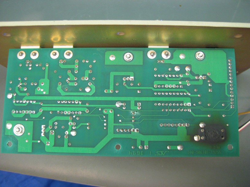
The board is double sided, making it a little more work to trace, but still possible. The 24V on the board goes to a number of other locations. It appears that different sections have different supplies. Two of the destinations are these paralleled power resistors. The other side of the resistors go to the input terminal of a MCT7805CT 5V linear voltage regulator. The third destination goes to an LM317T adjustable linear voltage regulator. The bottom side picture below shows the 24VDC trace as the large one towards the bottom
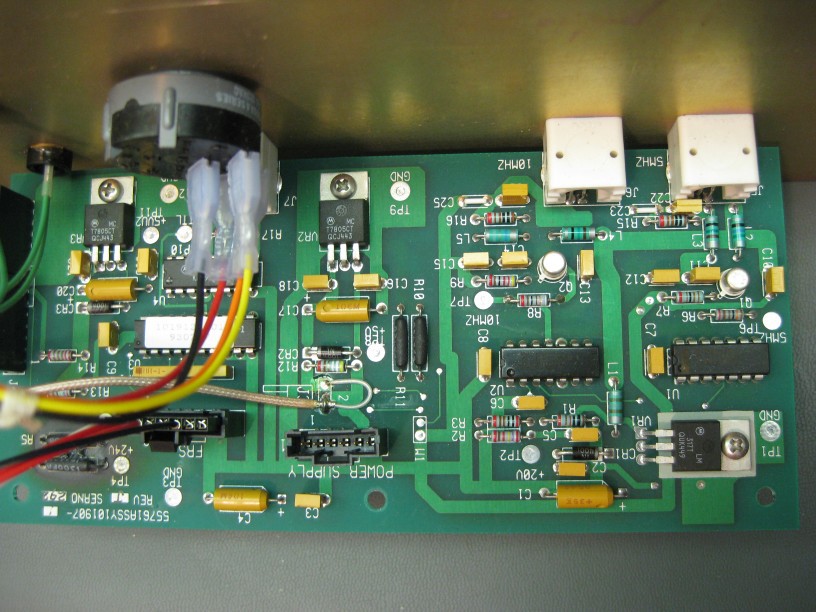
I've not seen this method of using series resistors on the input before, but suspect it is to have increasing voltage drop when the output current of the regulator goes up. This may be to share some of the heat and keep it away from the 7805, or as over current protection.
The 7805 (and 317) circuits have the recommended design of input and output capacitors and a reverse voltage protection diode, so everything looks good there.
The output of the second 7805(with the still intact source resistors) shows a good 5V. Voltage across the resistors is 2.0V, meaning 30mA of current is flowing. The 60mW dissipated in the resistors is not even perceptible as heat by touching them.
With the series resistors measuring >1Mohm, I would expect voltage on the other side, but there is about 0.5V measured on the 7805 input, so there is leakage through some part of the circuit. With power off, it is >1Mohm between the input and ground, and 4.5K between the output and grown, so nothing appears to be shorted which would explain too much current through the resistors to cause the board to burn.
If the output of the 7805 had been shorted, the resistor would have dropped most of the voltage, resulting in only 0.37A, well within the spec of the 7805. However, that would have been dissipating over 8W in those resistors, which seems plausible that it could have heated to the point of burning the PCB, and double their capacity such that they likely would have failed as they have.
The output of the regulator in the failed section goes to only the power(16) and enable(12) pins of a MC3481P line driver, it's decoupling capacitor and a resistor feeding the front panel power LED(explaining why it didn't come on). The C driver output pin(9) goes to the TTL output BNC directly with a 500ohm pull down to ground. The other 3 outputs of the driver chip are unconnected, and inputs grounded. This leads me to believe that either the 3481 line driver failed, or its output was nearly shorted in use, and sufficient current passed through it.
Having seen frequency standards often connected to the 50 ohm external reference input of test equipment, and often chained with BNC splitters, I can see how this could happen. Chaining just 4 loads would result in potentially 0.4A, which as seen above, could result in the excessive power in the series resistors. While these devices reference inputs are not intended to take 5V TTL inputs, I can see someone accidentally using that output from this box instead of the intended sinusoidal output connector.
While using the resistors as a first to fail device seems like a not unreasonable solution, I would have preferred a replaceable fuse. This seems like the intended design as the other 7805 is what powers the rest of the 5V logic on the board, I guess to isolate these.
Discussions
Become a Hackaday.io Member
Create an account to leave a comment. Already have an account? Log In.