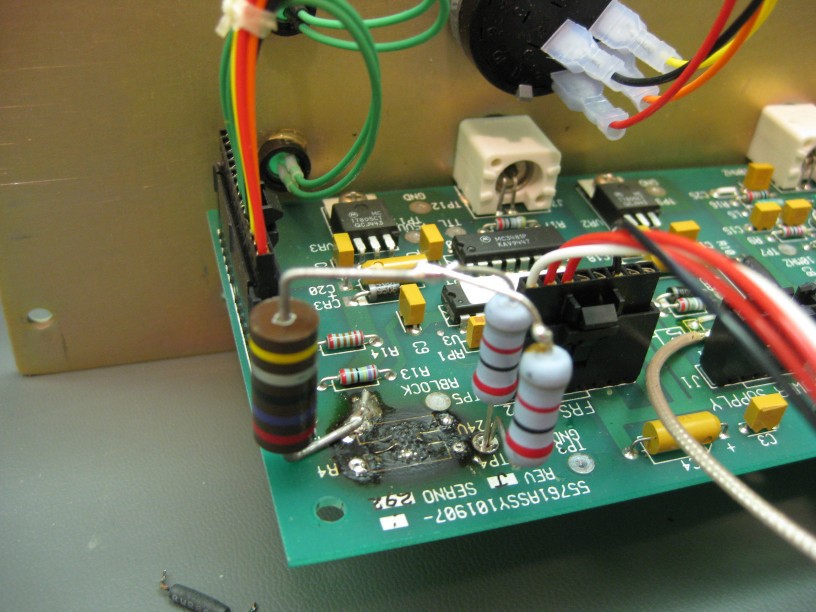
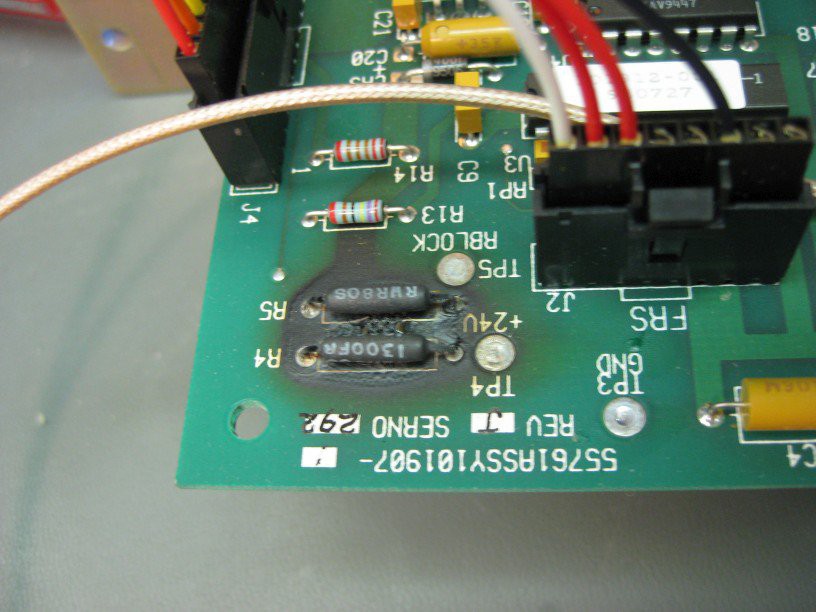
• EFRATOM PRFS-102 Repair

    Quinn12/01/2017 at 01:53 0 comments

    Powering the unit up again, and after waiting for the reference to lock, I used an external supply to apply 8V to the input of the 7805, after the series resistors.  Measuring the output showed 5V, and the 10Mhz now comes out the TTL output, so it seems like repair will only take replacing the resistors.

    My stock of power resistors is limited, and I didn't have any 130 or 33, or similar values I could use to make up the 65 result.  I did have some other values, and decided to parallel two 82 ohms, and add that in series with a 26.  Thus results in 67, very close to the original.  The slightly larger resistance will slightly reduce the current drive that is possible, but still will net almost 0.254A while maintaining voltage spec, and up to 0.33A at short circuit.  Calculating the power in each resistor results in a larger margin than the original solution.

    I bodged them in, standing up off the board so that if they ever overheat, they won't burn the board.

    Testing, this worked.   After putting it all back together, I tested further.  The outputs are all stable.  10Mhz sine output is clean, with 4.2Vpp(centered around 0) into 1Mohm, and 3.0Vpp in 50ohm, as expected.  The 10Mhz TTL output is clean with edges between 0.18 and 4V. (50ohm terminated with coax connection to scope, or in 10Mohm via probe)

    On to the next one then!

  • EFRATOM PRFS-102 Debug

    Quinn12/01/2017 at 00:04 0 comments

    With the unit plugged into an isolation transformer for safety, I started probing around.

    24VDC coming from the supply is good.

    The board is double sided, making it a little more work to trace, but still possible.  The 24V on the board goes to a number of other locations.  It appears that different sections have different supplies.  Two of the destinations are these paralleled power resistors.  The other side of the resistors go to the input terminal of a MCT7805CT 5V linear voltage regulator.  The third destination goes to an LM317T adjustable linear voltage regulator.   The bottom side picture below shows the 24VDC trace as the large one towards the bottom

    I've not seen this method of using series resistors on the input before, but suspect it is to have increasing voltage drop when the output current of the regulator goes up.  This may be to share some of the heat and keep it away from the 7805, or as over current protection.

    The 7805 (and 317) circuits have the recommended design of input and output capacitors and a reverse voltage protection diode, so everything looks good there.

    The output of the second 7805(with the still intact source resistors) shows a good 5V.  Voltage across the resistors is 2.0V, meaning 30mA of current is flowing.  The 60mW dissipated in the resistors is not even perceptible as heat by touching them.

    With the series resistors measuring >1Mohm, I would expect voltage on the other side, but there is about 0.5V measured on the 7805 input, so there is leakage through some part of the circuit.  With power off, it is >1Mohm between the input and ground, and 4.5K between the output and grown, so nothing appears to be shorted which would explain too much current through the resistors to cause the board to burn.

    If the output of the 7805 had been shorted, the resistor would have dropped most of the voltage, resulting in only 0.37A, well within the spec of the 7805.  However, that would have been dissipating over 8W in those resistors, which seems plausible that it could have heated to the point of burning the PCB, and double their capacity such that they likely would have failed as they have.

    The output of the regulator in the failed section goes to only the power(16) and enable(12) pins of a MC3481P line driver, it's decoupling capacitor and a resistor feeding the front panel power LED(explaining why it didn't come on).  The C driver output pin(9) goes to the TTL output BNC directly with a 500ohm pull down to ground.  The other 3 outputs of the driver chip are unconnected, and inputs grounded.  This leads me to believe that either the 3481 line driver failed, or its output was nearly shorted in use, and sufficient current passed through it.

    Having seen frequency standards often connected to the 50 ohm external reference  input of test equipment, and often chained with BNC splitters, I can see how this could happen.  Chaining just 4 loads would result in potentially 0.4A, which as seen above, could result in the excessive power in the series resistors.  While these devices reference inputs are not intended to take 5V TTL inputs, I can see someone accidentally using that output from this box instead of the intended sinusoidal output connector.

    While using the resistors as a first to fail device seems like a not unreasonable solution, I would have preferred a replaceable fuse.  This seems like the intended design as the other 7805 is what powers the rest of the 5V logic on the board, I guess to isolate these.

  • EFRATOM PRFS-102 Inspection

    Quinn11/30/2017 at 22:49 0 comments

    Starting with the EFRATOM PRFS-102 module, it is a pretty basic case, likely a generic one and put together by EFRATOM.  The front panel has isolated BNC connectors for sinusoidal 10Mhz and 5Mhz outputs, and a TTL output with selectable frequency.  A rotory switch selects between 1, 5 and 10Mhz.  When plugged in, the power LED does not come on, but after warmup, the Rubidium Lock LED does turn on.  The outputs have no signal.

    The lid removes simply to show a basic construction with an off the shelf cage power supply, the Rubidium module, and a circuit board attached to the front panel.

    The power supply is 24VDC, and tests good.  Pulling off the front panel to access the circuit board I could get a good look, and immediately find a problem.

    The PCB is very much burned under a pair of resistors:

    As it's a uncommon resistor, it is labeled with a full part number RWR8031300FR which reveals them to each by high reliability 2W 130ohm 1% resistors.  Measuring across them shows open circuit.  There are another pair in on the PCB which appear to be used in a similar way, and as they are wired in parallel, do measure 65ohm.

    The traces show that the 24VDC from the power supply come onto this board, and in addition to local circuitry also go to a connector which powers the Rubidium module.  This explains why some of the board logic does not operate, while the module does.