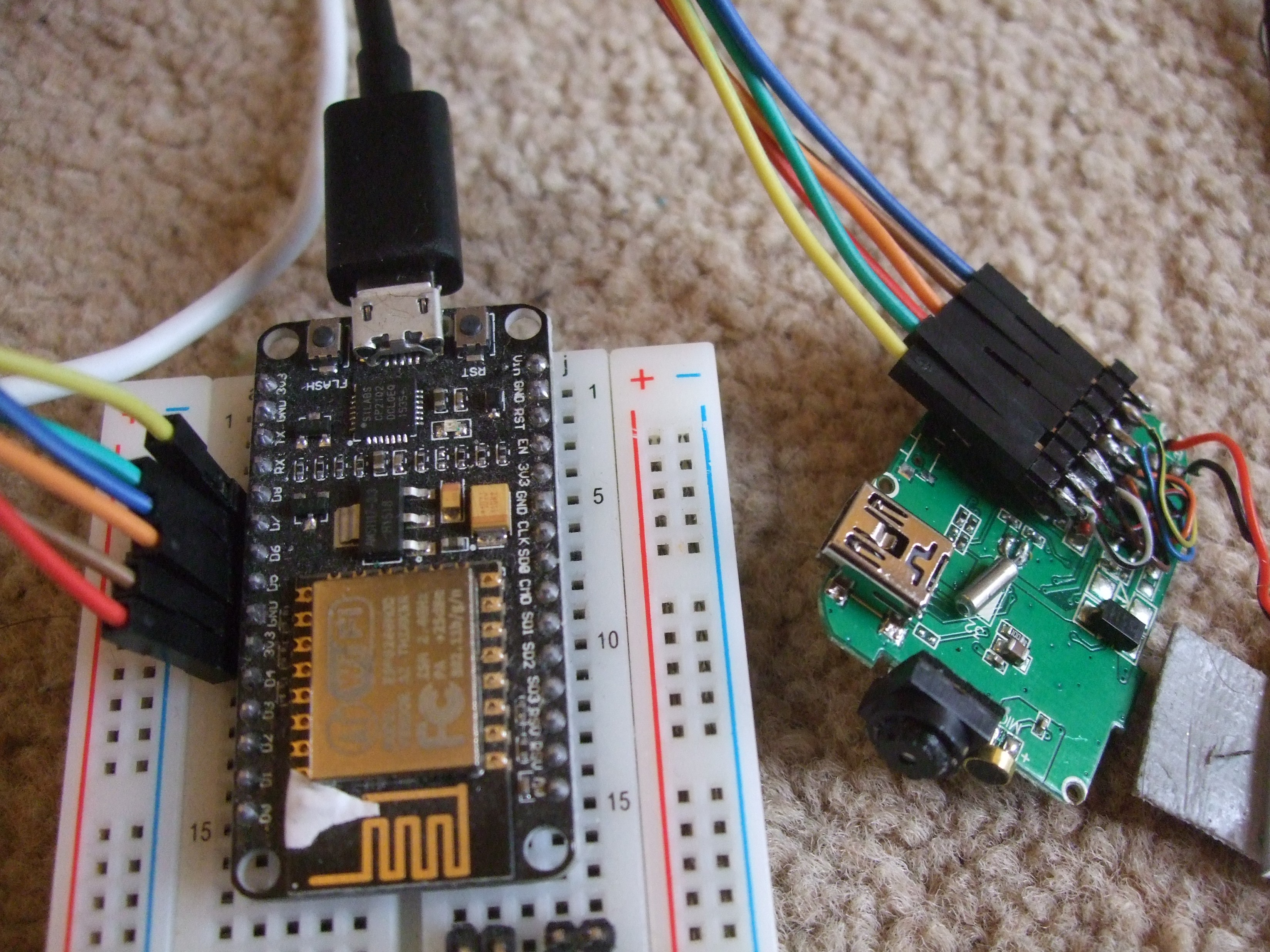
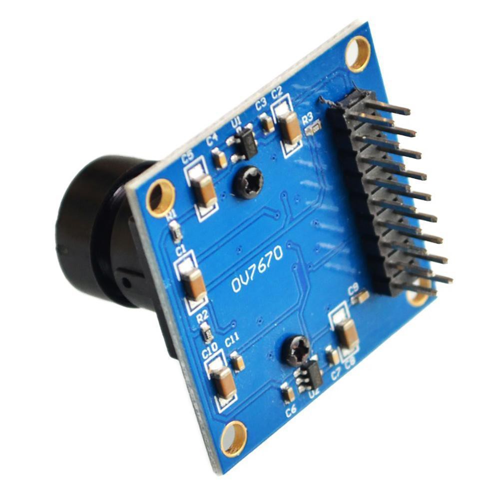
• POWER and the 808 camera module

    Fractal12/24/2017 at 18:10 0 comments

    From the last log it was determined the camera module needs at least an on off switch.

    "Since the ESP8266  cannot boot properly with the SD card and camera attached and powered, the power line for the camera must be default off, and switchable by the ESP8266. Drive current per pin is 12 mA on the ESP8266, the camera module takes probably 50-100 mA. So can use a transistor with gain 10+, or a mosfet to match whatever the ESP8266  has by default as a pullup). Or, could have a voltage regulator with an off switch."

    A quick test shows the camera module will not run without a battery connected (and power supplied through the SD card pin). It also looks like it's got some power regulation circuitry built in - perhaps that could be piggybacked also?

    (Not the implication is that both the ESP8266 and the camera module would have local 3.3v regulators, with is good practice if incoming power is unstable).

    Onto reverse engineering, the best part of any hack. The goal is to find some way to splice in the esp8266 as a power switch.

    1: High quality pictures of both sides of the board:

    2: Identify main chips:

    24-pin: "55DC MQNV054.1 1637" A mystery custom chip that runs the camera.

    8-pin: "FT25H045 7K10fG" a 4 Mbit SPI flash chip, presumably config or buffer.

    5-pin: "LTH7"  LTC4054 standalone Li-ion charger chip. 

    3-pin: "A1SHB" note 'S' has bar above. SI2305DS p-channel power mosfet, probably.

    3: Try to figure out what's going on.

    Where's the regulator?!? Somehow li-ion voltage gets dropped to 3.3 V. either I've misidentified a chip, or it's in the custom one. A quick check on the only possible canditates (5 poin and 3 pin) confirms they're not outing 3.3v. This still makes sense since there's a lot of capacitors around the main chip.

    What does the mosfet do then? It's connected to the main chip on it's gate, the drain is connected to +BAT, and the source is connected to... some thick wire that leads to the -ve end of a diode attached to the 5v usb port. When switched on, current will flow through the usb port, through the diode, and into the battery? It's a bit weird. during normal operation it's not active. It's weird because the LTC4054 chip has a built in regulator to feed the battery with an appropriate voltage. Which it uses. This is presumably so the device operates without a battery connected?

    Hmm, this is basically strange all round. There's clearly a split power bus, the main chip expects a VBat (3.5-4.2 V or so), and it handles the SD card power itself.  This is annoying, since it's all on one chip it's not easy to modify, especially without a datasheet. There's a RTC on board that needs VBat, but that's not critical. 

    Fine. Operation without a battery then: I don't want a battery in the camera being run for a long time. Quick tests with a usb cable show it won't operate the camera when there's power being provided through USB.  So instead, it would need a regulator set to ~4 V for the main electronics, and a separate 3.3 V regulator for the microSD. Difficult, and costly.

    If only there was some way to use the built in regulator, without the camera using the SD card. It's a good thing this is a hack, not a  product, because there is a way! When the camera is held in RESET, the SD voltage appears enabled.

    There is no reset switch fitted, but the pads are there - and the switch would pull a pin to GND. The pin is 0V when in STANDBY, but is 1.3V when IDLE. The reset current is 22 mA, which is unfortunately close to the ESP8266's "around 20 mA". It may only pull the reset pin halfway. Still, can use two GPIO pins at a stretch, or a transistor. 

    I also checked the other two buttons - POWER connects VBAT to a pin, and works fine with 3.3v instead, needs to be held for ~1 second, and has a current of 0.22 mA - perfect for an ESP8266 pin. SHUTTER connects a pin to GND, and the pin floats at 3.3 V. Current is 0.033 mA. It...

    Read more »

  • Intial camera test results

    Fractal12/24/2017 at 13:17 0 comments

    Both locally shipped cameras have come in, just in time for the weekend. 

    Both work, are the same (barring some build quality, and are some kind of version 9 Version #29  (here)of the 808 - definitely a 640*480 sensor, images and video upscaled. They can't do terrific frame rates, but that hardly matters for this application.

    So I've done several things :

    Confirmed you can change the focus with a pair of pliers... this is actually really tricky! Will sort it out finally when the device is mounted. 

    Measured SD card voltages: All 3v3 (besides GND) when Idle. All 0V when Standby.

    Measured pullups: ~8K for most when Idle, ~6 M when Standby.

    Power modes for camera are:

    ACTIVE: The camera is writing to the SD card (the moment after a picture is taken)

    IDLE: The camera is ready to take a picture, but is not doing anything. This turns to standby after 30 seconds or when power button held.

    STANDBY: The camera is in it's low power state: A RTC is running, but the SD is off and there is no access.

    OFF: There is no power connected to the camera.

    I've aslo skipped ahead and connected it to the ESP8266, running NodeMCU 2.1. This was achieved by soldering some fine wires to the 1 mm pitch microSD header, and breaking them out to a row of male 0.1 inch headers. These were jumper wired to the ESP8266:

    This got some results! The ESP8266 CAN READ the SD card subject to the following: The camera is in STANDBY, AND The SD power pin is connected AFTER the ESP8266 boots. 

    The camera can write to the SD card subject to the following: The 4 GPIO pins on the ESP8266 are set to INPUT FLOATING. The SD power pin has been plugged in AFTER the GPIO pins are set to float.

    So the camera being STANDBY affects the ESP8266 booting, and the ESP8266 defaults, or having done communication affects the camera booting. 

    So as a reminder, there were several tests to do once a camera had come in, now answered.

    1. At what voltage does the camera/SD card operate? 3.3 V.
    2. What state are the pins on the SD card when the camera is on standby? ~8K pullups. 
    3. Is there any data access when the camera is on standby? Not obviously. (may be very occasional access, requires a longer test)
    4. How can you tell when the camera has successfully taken a picture and has returned to standby? (LED goes out, CLK, DI, DO drop to 0V)
    5. What state are the pins on the SD card when the camera is depowered? Not measured.
    6. What current flows on the data pins into the camera when the camera is depowered? Not measured.
    7. When the ESP8266 is not reading the SD card, what state are the pins? when set to float, most are 330k pulldowns, except pin 8 which is 10k pulldown.
      • What software changes are needed to tristate them in between reads? set all to gpio.INPUT, gpio FLOAT.
    8. Can the ESP8266 read the SD card when the camera is off and unpowered? Not tested.
    9. Can the camera take a picture with the ESP8266 attached but not writing? Yes subject to some ordering.
    10. Can the ESP8266 read the SD card when the camera is on standby, without crashing it? ESP8266 can read SD card, camera needs a (SD pin) power cycle afterwards.

    So the CS pin is being weird. I'ts pulled down on the ESP8266 by about 10k, and pulled up on the camera module by about 8k. This is fine while it's being actively driven. The other pins are pulled down on the esp8266 by about 330k. I don't yet know whether this is specific to that pin, the software, or the NodeMCU board. It can be changed easily, but shouldn't have much effect apart from confusing the SD card occasionally.

    Overall this is very promising! All wires can be shared with both the camera and the ESP8266, except SD card power. in fact, power will be something to consider soon - the camera module has a battery, and that's no good for long term. 

    Since the ESP8266  cannot boot properly with...

    Read more »

  • Camera SD card piggybacking an ESP8266

    Fractal12/21/2017 at 14:47 0 comments

    One part of the project that could be widely reused is the piggybacking of the ESP8266 onto an existing SD card, or microSD card. This may or may not be feasible easily - it depends on the device in question.

    The ESP8266 doesn't require much in the way of hooking up to sd card - it can use a SPI connection with only 4 pins: CS, DI, DO, CS (ClocK, DataIn, DataOut, Chip Select). I'm following the hookup guide for nodemcu: https://nodemcu.readthedocs.io/en/master/en/sdcard/#sd-card-connection

    The first check is whether this clashes with anything else on the ESP8266 side - after all it has a flash chip on board - what if they shared SPI lines apart from the chip select wire? Then accessing the internal flash could clash if the camera was on.... Checking the schematic found here http://www.esp8266.com/wiki/doku.php?id=esp8266-module-family#esp-12f, it turns out the ESP8226 has a separate set of SPI pins operating (typically) in QIO (quad input/output) for the on-module flash. The pins for an SD card connection are separate - great!

    Next is the voltage -  The ESP8266 module operates roughly from 2.5-3.6 V. I don't know what the keychain camera will operate on - but it's going to be roughly in the 2.5-3.6 V region due to the microSD card's limitations. At least they won't fry each other accidentally this way...

    Bus contention. Basically, the project must avoid a scenario where both the camera and the esp8266 are trying to drive one pin opposite ways. SPI lines are driven both high and low (a.k.a. totem pole), unlike I2C, so this is a genuine concern. According to the spec, when not in use the bus pins are left floating (a.k.a tristate) (apart from CS), but this is a random cheapo chinese camera, so who knows? There's also the consideration that either the camera or the esp8266 may give problems when bus access is going on without them starting it. (once the SD module is initialized!). 

    There are three ways really to deal with this, in order of increasing difficulty:

    1. Access the card when camera is in standby, assuming it never makes SD access, and floats it's bus pins. Wire CS such that ESP8266 can override it. Simplest solution.
    2. Access the card when camera is depowered, and power SD card separately. Note camera module must not be back powered by the I2C bus!
    3. Separate out the 4 SD wires on a switch, and use the ESP8266 to direct them to either itself or the camera. Also possibly power SD card separately.

    Obviously there are some checks to do, in order : 

    1. At what voltage does the camera/SD card operate?
    2. What state are the pins on the SD card when the camera is on standby?
    3. Is there any data access when the camera is on standby?
    4. How can you tell when the camera has successfully taken a picture and has returned to standby?
    5. What state are the pins on the SD card when the camera is depowered?
    6. What current flows on the data pins into the camera when the camera is depowered?
    7. When the ESP8266 is not reading the SD card, what state are the pins?
      • What software changes are needed to tristate them in between reads?
    8. Can the ESP8266 read the SD card when the camera is off and unpowered?
    9. Can the camera take a picture with the ESP8266 attached but not writing?
    10. Can the ESP8266 read the SD card when the camera is on standby, without crashing it?

    To achieve most of this it will be necessary to attach wires to the camera module SD card pins, and probe with a multimeter and oscilloscope if possible. The ESP8266 can act as a rudimentary logic analyser if needed (by triggering on pin change), so it could at least detect bus activity. One can also use a microSD extension adapter to break everything out in a more accessible and sturdy way, but they're slow to order. I intend to break it out onto a small breadboard to prototype with by soldering small wires on. Hopefully the camera module will be really easy to work with - it would be annoying to have to go the switch route!

  • Cheapest camera modules

    Fractal12/21/2017 at 12:34 0 comments

    So I have now ordered three of the cheapest 'keychain' camera modules I could find on eBay.co.uk. I've gone for 

    • The cheapest anywhere (China), £2.98 from "326fruit"
    • The cheapest UK, £4.20 from "to-habi"
    • The cheapest UK with fast shipping, £5.99 from "i-spy"

    Having looked over http://www.chucklohr.com/808/ , I'm not expecting much at this price. I'm very unlikely to get anything with a sensor that's more than 640x480, and if they're otherwise broken it won't be a huge surprise. I fully expect the cheapest sellers to disappear before a refund would occur.

    Nevertheless they should work enough for a picture, even if there are small faults to fix.

    Obviously were you to spend more, and use reputable sellers with good feedback, you could get a much nicer camera. But at the moment I want cheap, and I want to be able to open them up and hack them without worrying about the cost. After all, any warranty is going out the window the moment the lens is opened and the IR filter removed. Not to mention soldering to the microSD card slot.

  • ESP8266 SD card webserver with server side scripting

    Fractal12/21/2017 at 12:18 0 comments

    This log is to detail the requirements and challenges required of the wireless module. Fundamentally it is a webserver serving files from a microsd card and/or it's own flash memory. It also is sharing the SD card with another device, that the ESP8266 can power up and down.

    There are several simple webserver examples out there: e.g. https://randomnerdtutorials.com/esp8266-web-server/

    Or the much better: https://github.com/marcoskirsch/nodemcu-httpserver .

    Nevertheless, there are several things the webserver needs to be able to do reliably, that the simple examples don't necessarily cover. (though Marcos Kirsch's one is pretty complete on the webserver front and does several of these things perfectly)

    • Serve images larger than 2-4 kB
    • Server images fairly fast
    • Allow the module to do some server side scripting
    • Use that scripting to make an index that updates
    • Control a camera module to get live images though webserver
    • Not interfering with the sd card communication (i.e. have the pins float when not in use)
    • Keep on operating after 100's of refreshes.
    • keep on operating with 100's of images.
    • Pull time from NTP and edit SD card with time updates before enabling camera
    • Still provide a responsive webpage despite waiting on a slow camera.
    • Provide file upload to modify the scripts wirelessly. 
    • Allow file deletion, and bulk file deletion
    • Be able to handle a fresh formatted microSD card in the camera.
    • Limit connections on the ESP8266 to within it's limit of ~4

    Some of the solutions here can be hacks, it's OK if say, the module resets after every picture, it's never going to be a fast experience. Some things set requirements for later on - for instance everything apart from images is staying on the ESP8266's flash.

    The overall methodology I originally planned was to have lua commands embedded in html files, for some kind of .htmlua file. In that manner one file would be responsible for everything. However, this makes sending files quite complicated in that you have to scan for and buffer for commands every time the file is requested... it could get quite tricky.

    Instead the preferred technique as used in the nodemcu-httpserver project is to have .lua files which individually do the whole connection (and send some dynamic HTML), and some static html pages. Any hyperlink can also have a GET request easily, that info can go into the scripts, but the bulk of the work will be with a set of static .html files and using .lua files as dynamic pages. They'll get a bit unwieldy, but should be readable. Headers and stuff repeated often can be hidden in a .lua file, and called as needed.

    One obvious hard part is keeping the connection alive if the camera's taking many seconds to turn on. I don't want to go into dynamic web page content - the ESP8266 doesn't like having many simultaneous connections...instead it may simply have to either be slow, or show the previous image. Making a webpage auto-refresh is easy though.

    For now, the best bet appears to be https://github.com/marcoskirsch/nodemcu-httpserver. If I do manage to fix any generic problems with it, it's open source so I could submit a pull request. 

  • Cameras and Arduino or ESP8266

    Fractal12/19/2017 at 15:07 1 comment

    This should summarize the options available for getting a camera usefully connected to a microcontroller.

    This is NOT about simply putting a remote shutter on a camera for a time lapse jig, this is about getting the data usefully out so a micro can use it.

    The main problem is that a picture, even 640x480 (0.3 megapixels), is much larger than the ram on cheap microcontrollers. The second problem is that most cameras need the data to be clocked out far quicker than cheap microcontrollers can process. The third problem is that a lot of cameras need configuring before use, even if they have automatic modes for contrast, white balance, etc. you still need to set them up.

    Now there are options - you can look at only very small parts of an image, and ignore the rest. I've done this with a simple old CMOS camera at 2 MHz and an Arduino (ATmega328p) - it could read one line, send it over serial, and then a frame or two later read the next line. For slow moving objects this can work, but the microcontroller really can't do much else - even for a slow, 2MHz camera the ATmega328 is completely tied up while a line is being read - every 8 clock cycles a new byte of data comes in, and it takes at least 4 cycles to copy the data into ram, let alone synchronize with a data stream. You're never gonna get a good image since it can't hold the whole frame at once. 

    There's also the option of using a more powerful device - a cheap raspberry PI zero can easily handle the data stream from a camera, but I'm wanting a lower power, even lower cost device than that.

    So overall what's wanted is a camera module which has memory on it, and some high speed buffer to store each frame. The excellent ArduCam project is the logical conclusion to this, though it adds cost. A microcontroller can then access the picture slowly on a simple protocol, like SPI. Or an ESP8266 could stream the picture out of memory slowly over WiFi, in little 2 kB packets.

    The low cost options:

    £2.40. OV7670.

    A OV7670 module with a nice big lens on a pcb with a 2x9 header. The cheapest result for "arduino camera" on ebay.co.uk. Also, completely unusable on nearly every Arduino. The OV7670 is a VGA CMOS module, it outputs pixel data over 8 pins, which update at a minimum speed of...10 MHz. The controller has to provide that 10 MHz too, plus there's some synchronization signals there too. 

    Now, some people have got some semblance of functionality working with a small device ... but it's not very good honestly. Scroll down to 10: Results, at this instructables: framecapture, It's impressive but sad.

    The Arduino is running 100% dumping all 8 bits of PORTC out of the serial port at 128 Kbytes per second. (Quick aside - that's 128*8 = 1 Mbit per second, which is the fastest any arduino could possibly go at 16MHz)

    It requires special software to receive and process this unformatted data, it's only reading one of the colour channels, it's only reading 320x240, and it's still underclocking the camera. Overall, not usable on anything short of a raspberry PI.

    £19.99. Arducam Mini. 

    This is the logical conclusion to prototypers needing a camera on an underpowered platform. Arducam have good open source documentation too! It's a CMOS module (OV2640) attached to a FIFO ram buffer, and a controller on board to handle shuffling bits around. It's terriffic, and you can even attach multiple ones to microcontrollers for 360 vision! They have easily changeable lenses too. Full details on their website: ArduCam mini.

    However, £20 is a lot! It would be the majority of the project cost. Really the cost is the only downside!

    £7.35. OV7670 with AL422 FIFO.

    It looks like the OV7670 with a big old FIFO slapped on. Because it is. Now this is a bit more feasable, there are people asking how to use it on stackexchange... but it's still a lot of work. It's also got a crystal onboard,...

    Read more »

  • Project design brief

    Fractal12/19/2017 at 14:18 0 comments

    This is a summary of what the project will entail.

    The end goal will be photos accessible from any smartphone, tablet, or computer on a wifi network, of nesting birds. Ideally past photos will also be available, as will a live view. The crucial aspect is that it must be cheap, ideally under £20 for all parts in a one-off. This will encourage other people to try it themselves, and make the project innovative. Ideally the different modules in use will be able to be changed, or re purposed easily.

    At the time of writing, the current commercial offerings are:

    ~£40-£300 : A nest box with a small IR camera, which streams PAL/NTSC video to a reciever attached to TV. No memory, only needs power lead.

    ~£2-30 : A webcam on a long cable. No memory, no IR, requires computer on and receiving. Limited by USB transmission over long cables.

    ~£100 : A trail camera with IR, and an internal SD card. Logs, but requires human access to get data. Also available with SIM card and 3g transmission, with associated costs.

    There are probably others - worth adding in comments if you know more.

    The important bit is that none of them meet all the goals.

    This project can be thought of as a number of modules with their own criteria.

    The following is a very rough diagram of the different parts working together.

    The basic mode of operation is as follows: User connects web browser to webserver hosted by Wireless Module. It serves a page containing a most recent picture, and allows download of timestamped previous pictures to the browsing device's memory. It may also allow deletion of files, or taking a picture on demand. Pictures are obtained by use of the Camera, lit by IR LEDs, and stored into the Picture memory module. Brightness, contrast, etc are ideally automatic.

    Of course, some things can be combined, such as the microcontroller and wireless module - just using an esp8266 as a microcontroller and a wireless interface for instance. Or, depending on the camera module, it may have a built in microcontroller and memory.

    Some parts are missing, such as all the power connections, and transistors for switching bits on and off, and the exact nature of the power supply. These can be decided after the demands on the power system are known. 

    Since it's a wifi device, it's time to give a quick thought on internet and security. The device could sit behind a router and connect out quite safely - the main reasons would be to get the time from an NTP server, to post pictures to an imagehost, or social media. However I would draw the line at having any ports opened on the router - it's much easier to make a secure device when it's not hosting a public webpage. Hosting a webpage accessible from within a wifi network is nice and safe though, plus the latency is low, and packet loss is minimal. Obviously an attacker from within the wifi network could be a problem, but by then it's game over anyway. Finally, the device will be connecting to wifi network, so must store the credentials somewhere - an attacker could steal the device and read off the credentials...but by then they're in your garden.

    Obvious first choice for the wireless module is the ESP8266, as it's the cheapest thing around. It's got some onboard ram, but nothing fast enough to take a whole picture (~200 kB). It has limitations as a webserver, but they have been worked around in other projects, such as sending large files > 2 kB. There is a choice of how to program it going roughly in order of abstraction: Bare metal, Arduino IDE, micropython, nodeMCU. The latter two are interpreted languages, which reduces available resources for programming, but makes various tasks easier. I'm choosing to go with nodeMCU as it's what I've used before, and people have made successful SD card webservers in it.

    Memory at a budget price with decent capacity for large logs: Has to be a (micro)SD card. They're available very cheap for <=2 GB capacity, interface reasonably with ESP8266 and Arduino with very cheap modules,...

    Read more »