0%
0%
 DrYerzinia
Become a Hackaday.io member
Already have an account? Log in.
Just one more thing
To make the experience fit your profile, pick a username and tell us what interests you.
Pick an awesome username
hackaday.io/
Your profile's URL: hackaday.io/username. Max 25 alphanumeric characters.
Pick a few interests
Projects that share your interests
People that share your interests
 Don Straney
 novirium
 Denys Zaikin
 core weaver
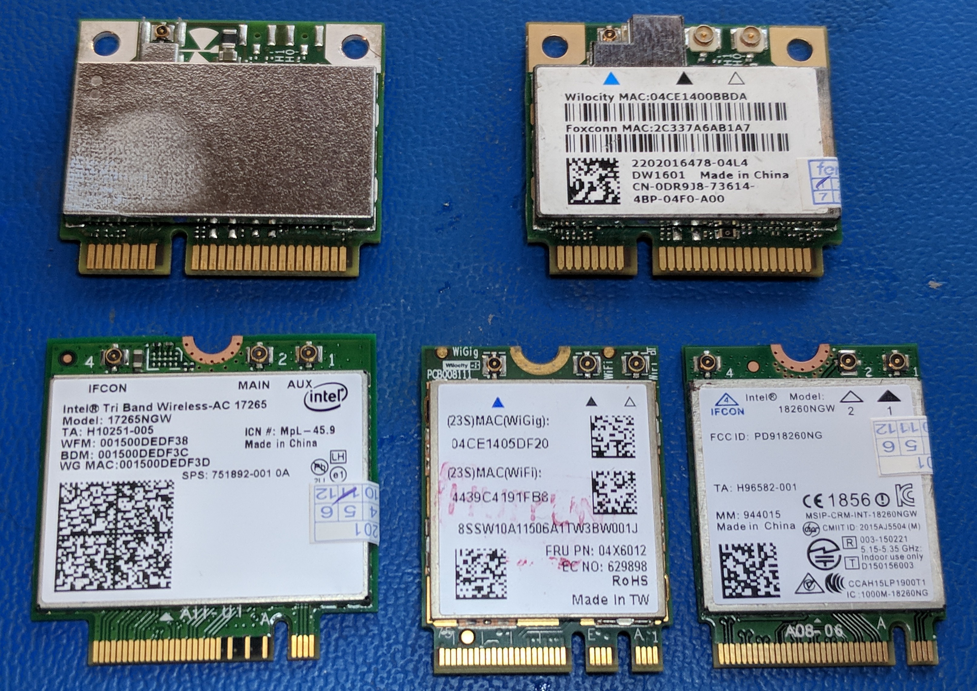
Lenovo card is QCA-Wilocity "Falcon" - likely some QCA9006 variation . It should use the same antenna as QCA9008 - but I'm not sure about drivers and compatibility with dock. Did you check what hardware IDs it returns?
QCA9008-TBD1 can be found in some Acer laptops (or sold separately on taobao). It also uses A+E key unlike A-key Intel.
Corresponding docking station is Acer Prodock Wireless, Antenna can be pulled from either Acer laptops/docking stations, or (expensive) 802.11ad-enabled routers using QCA9008-SBD1 radio like the one in the Acer dock.
(Windows) drivers are available on Acer website, and do not have any branding check unlike Dell.