 novirium
The drive behind creating InterBand comes from two places. The first is that while there are heaps of awesome wearable projects by makers popping up at the moment, many of them are having to cover the same ground before implementing the special features unique to their project. Things like Bluetooth, display drivers, and battery management circuitry are included in many of them without much reuse of designs. Wouldn't it be great if makers could instead use existing open source modules for these, mix-and-matching what was required for their project, and designing their own module to implement specialised features?
The second is to try and encourage people to use a bit more of the available real-estate on a wrist, arm, or ankle for their wearables. The established form-factor seems to be a small blocky thing on top of the wrist, with a flexible band holding it on. Bands created using InterBand would instead use the whole strap length to fit electronic modules, allowing more room for things like batteries, and making it easier to implement features without having to design everything to be extremely compact.
(side note: I'm not particularly attached to that name yet. It's simply the only thing I could come up with that doesn't already refer to another system or product. Suggestions welcome)
Project Goals:
To be a successful, useful standard, InterBand has several project goals.
- Open. I really want people to able to use this, which means getting as much input as possible. I'm yet to see how practical it is, but even the physical interface could be included in the GitHub repo if it's in a textual form like SCAD
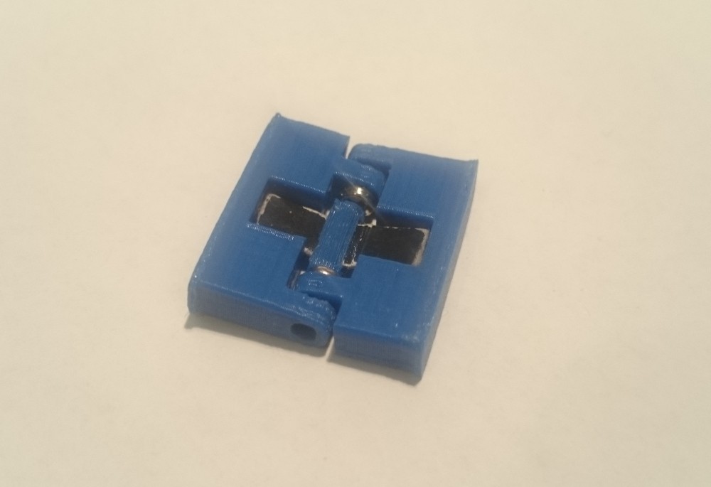
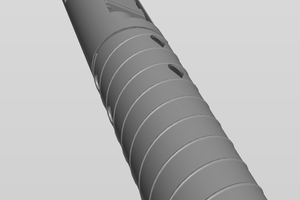
- Easily constructed. In short, ideally the whole thing can be 3D printed, with the option of milling it. This means that parts of the physical interface cannot be too small or fine, particularly around load points like the hinge. Ideally it would also be able to be printed without support.
- Cheap, and easily sourced. Any components that can't be easily fabricated need to be easily accessible.
- Low entry barrier. Example module STLs, and good documentation on the bus protocol.
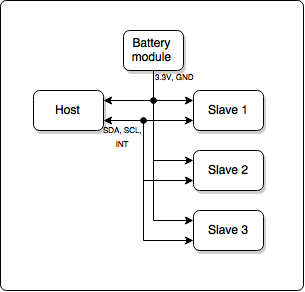
System Outline:

License:

This work is licensed under a Creative Commons Attribution-ShareAlike 3.0 Australia License.
 Quinn Morley
 alpha_ninja
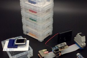
 William
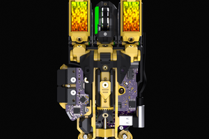
 benw
benw