zakqwy
-
NeuroBuggy v0.1
08/21/2015 at 04:38 • 0 commentsI added a new Motor NeuroBytes program for servos modified for continuous rotation, then mounted a pair of CR units in an old cellphone box. The program (https://github.com/zakqwy/NeuroBytes-v04/tree/master/FIRMWARE/v04run_servo-CR) makes a downstream servo rotate CW for ~1s when the excitatory dendrites get hit, and rotate CCW for~1s when the inhibitory dendrites get hit. In the video, three standard NeuroBytes run in a loop to generate a series of pulses that get sent to both Motor NeuroBytes quickly enough to cause uninterrupted rotation. When either switch is hit, the opposite Motor NeuroBytes module gets an inhibitory pulse and reverses until the next cycle, causing the NeuroBuggy to rotate in place and embark on a new trajectory.More details on the hardware to come.
-
NeuroBuggy Details
08/22/2015 at 20:06 • 0 comments![]()
Note 8/22/2015: Since the original NeuroBuggy post, I've made a few hardware modifications that are reflected here--namely, the two bump switches are moved from hook-and-looped cardboard tabs to permanently mounted devices, and the servos are reversed for better servicability.
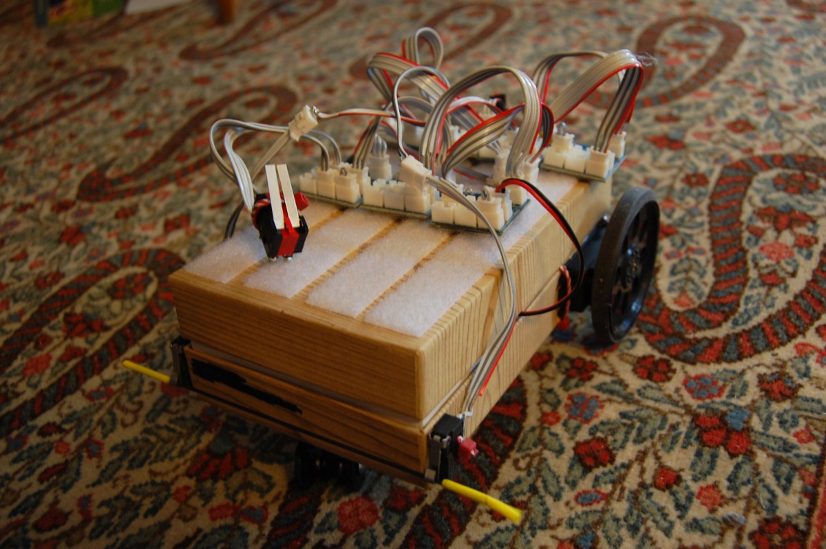
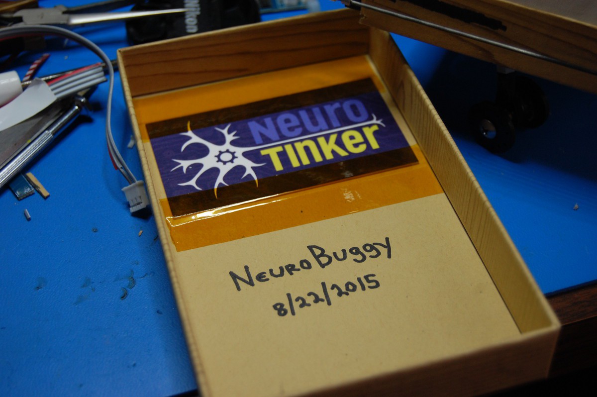
NeuroBuggy looks a lot like the Boe-Bot from Parallax, a fantastically versatile platform that pulls a microcontroller around on a pair of continuous rotation modified servos and a ball-shaped caster. The robot is lightweight, compact, sturdy, and generally excellent. Rather than a BASIC stamp (or some other microcontroller), NeuroBuggy is covered in the fuzzy half of commercially available hook-and-loop fasteners, allowing various NeuroBytes modules to be stuck onto the top to build out the vehicle's logic. The chassis is built from an old [fancy and likely product-MSRP-enhancing] cell phone box:
![]()
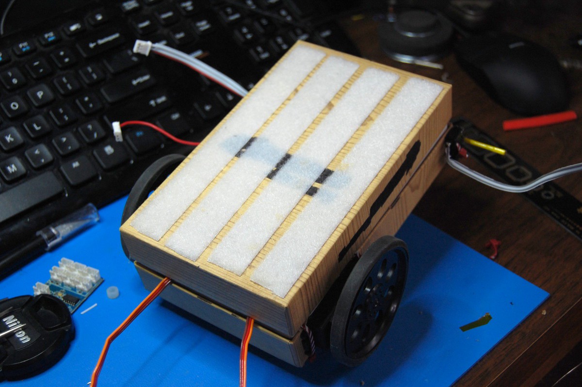
NeuroBuggy's lid can be lifted once the appropriate chassis cables are disconnected. The inner portion of the vehicle contains all of the drivetrain stuff:
![]()
On the left side of the picture, you see a fairly dangerous LiPo battery and a ludicrously loud alarm, designed to monitor all four cells and let me know when they've discharged enough:
![]()
![]()
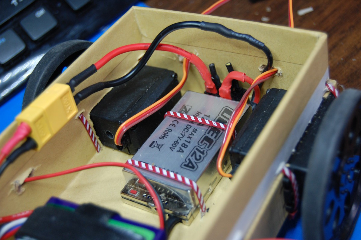
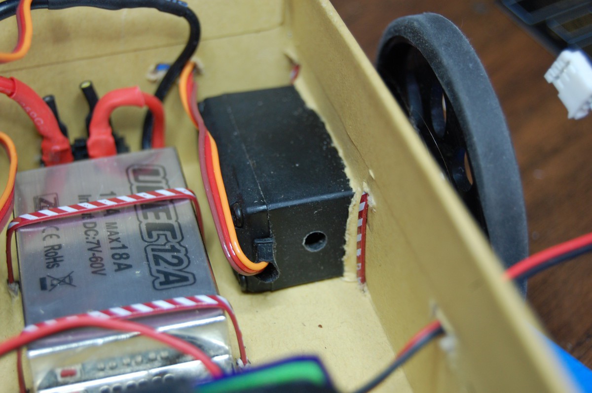
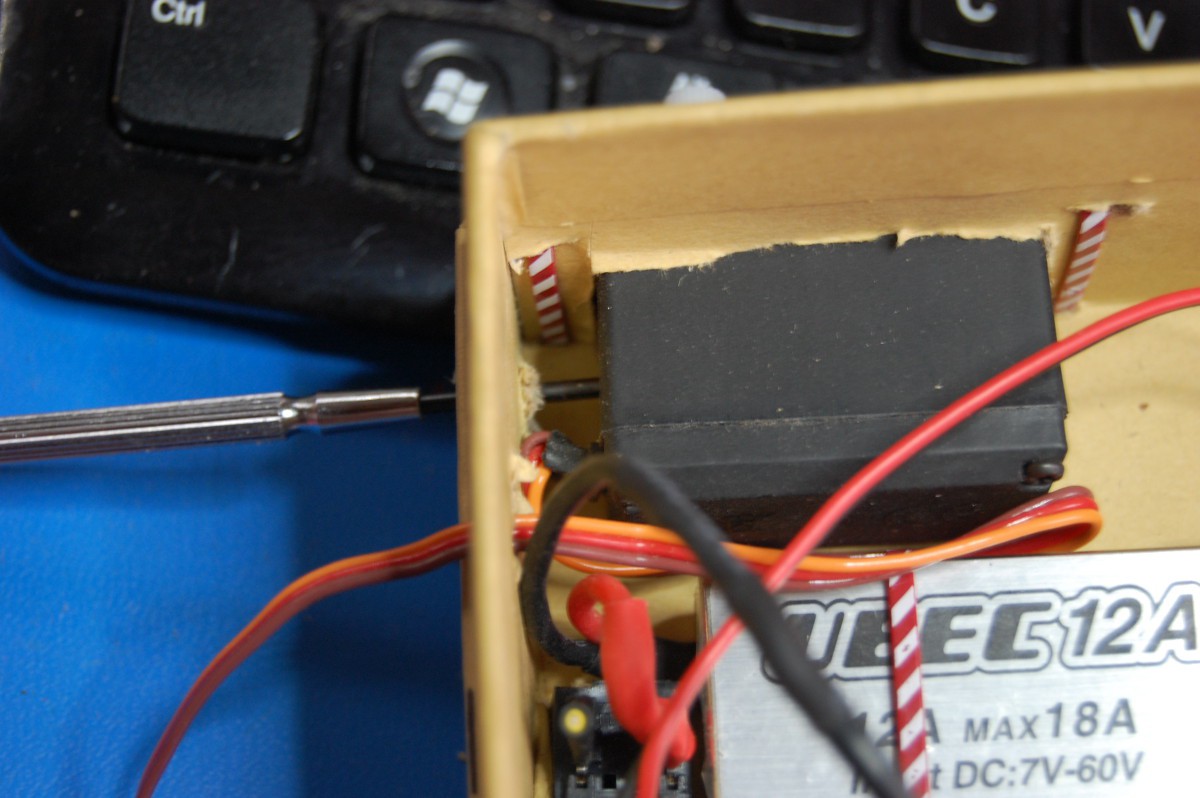
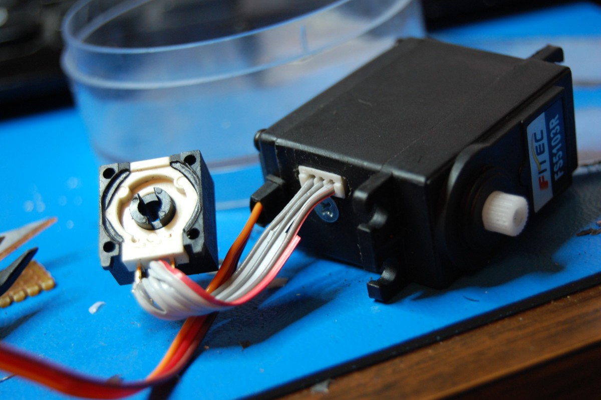
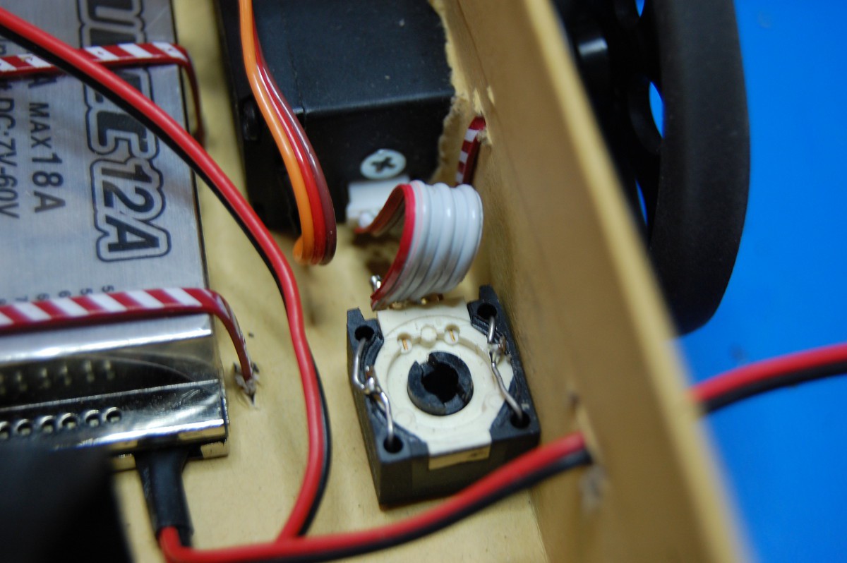
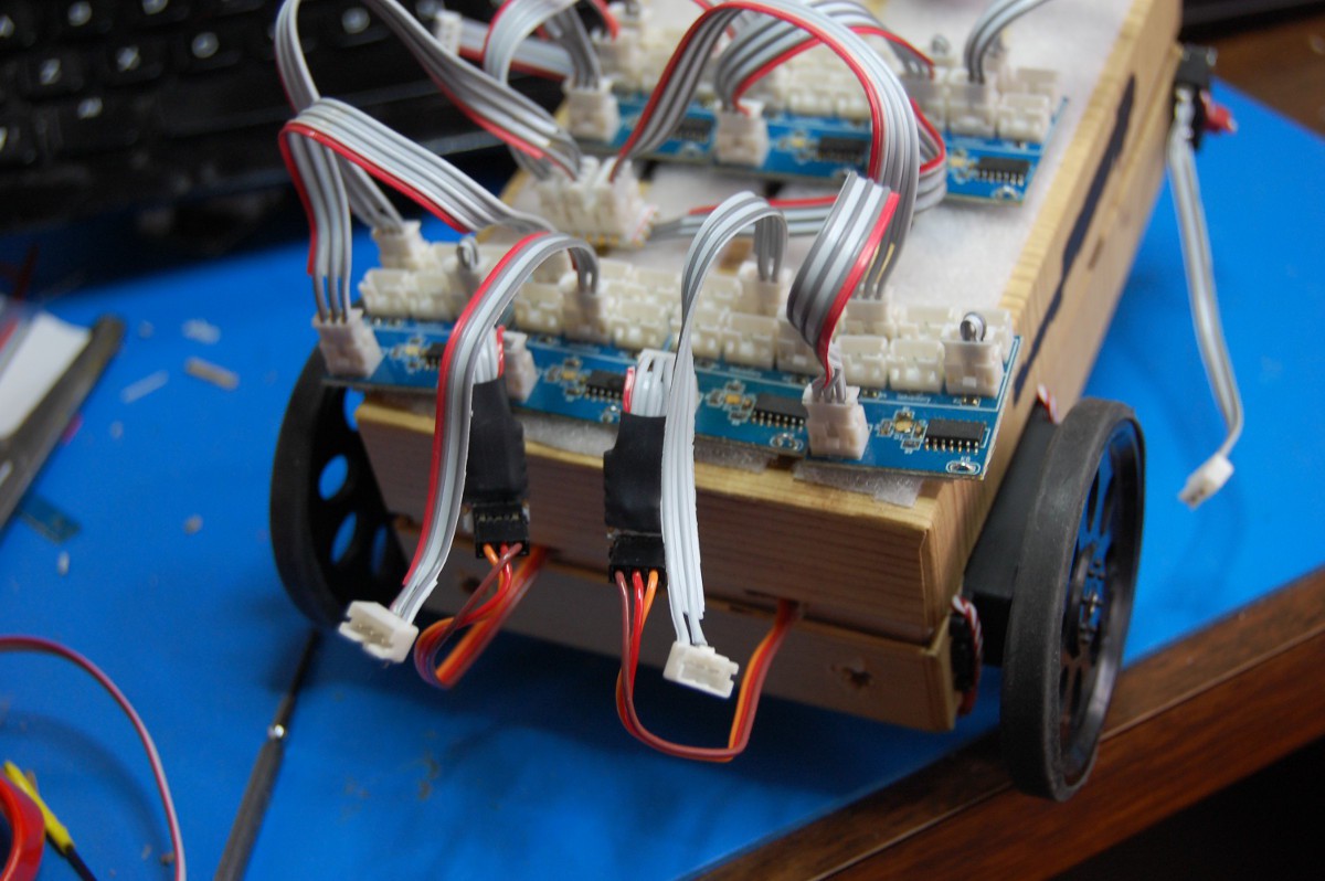
On the right side of the picture, you'll see more #GimbalBot hardware; a "battery eliminator circuit" (AKA a commercially available RC power supply), the back end of a power switch, and the two continuous rotation servos:
![]()
![]()
The pictures above [with visible pot calibration ports] were prior to an important modification: flipping the servo motors and putting a few holes in the chassis, so the calibration pots (needed to zero the CR servos) were accessible:
![]()
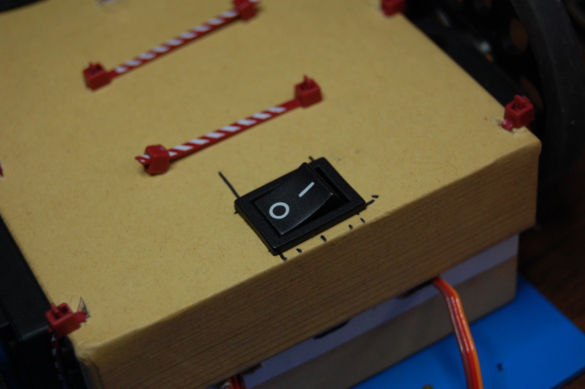
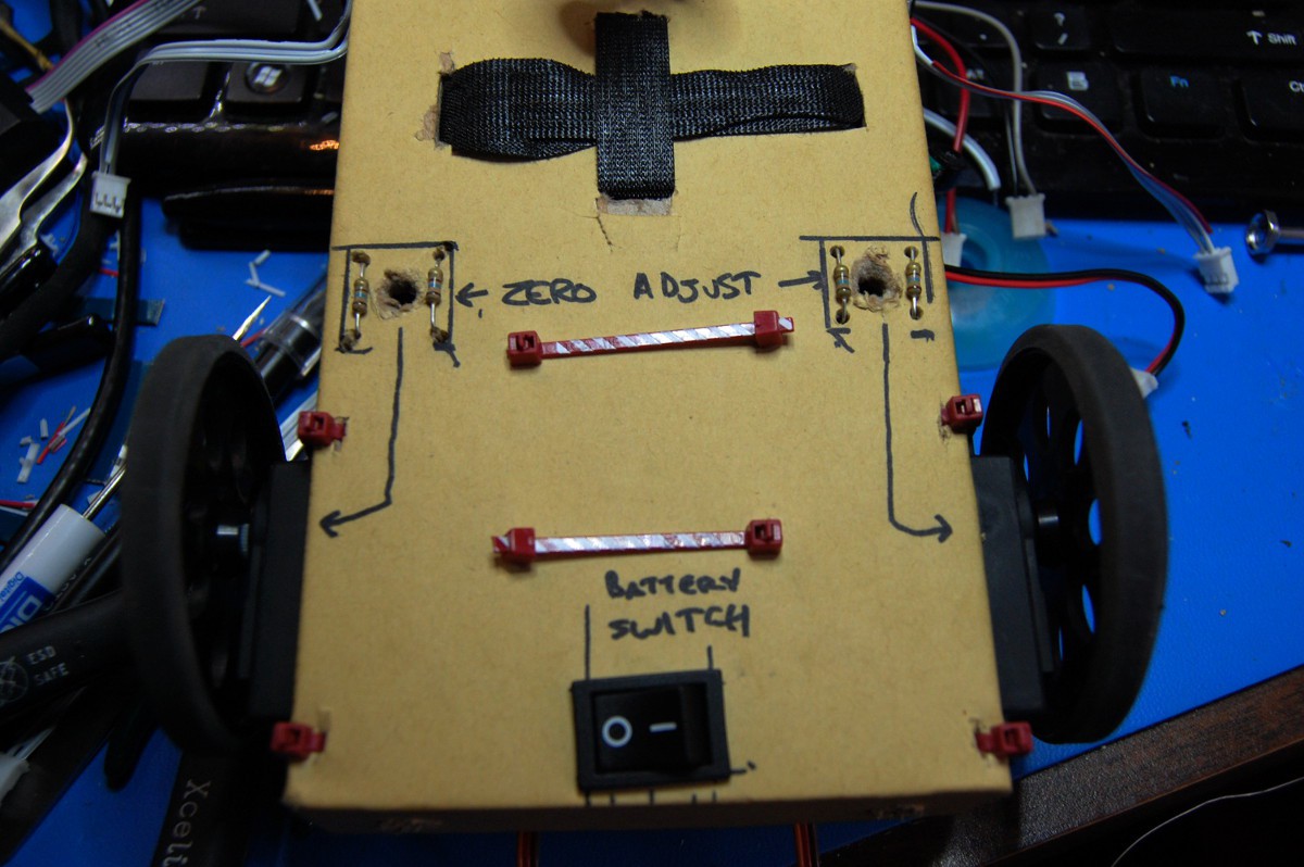
Flipping the chassis over shows the power switch:
![]()
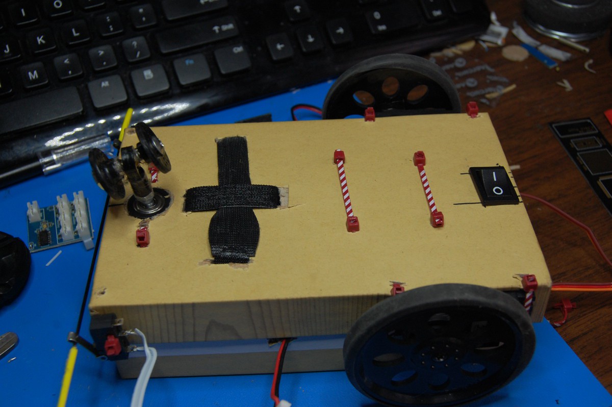
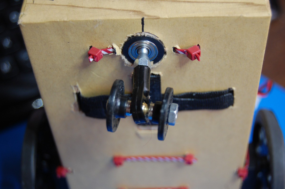
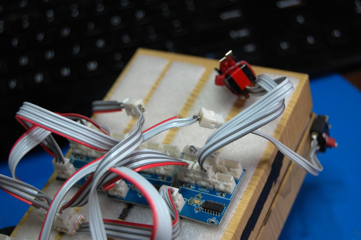
Zooming out a bit shows the bump switches (now v0.2!) along with the scrounged-together "caster":
![]()
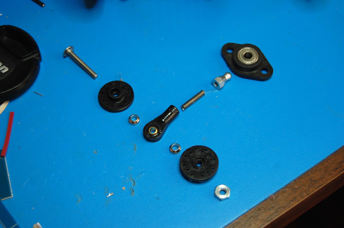
This is what makes up the caster:
![]()
[above: a slightly short 6-32 machine screw, two round servo horns, a heim joint, two beveled heim joint spacers, a 6-32 nut, a short length of threaded rod, a weird cap nut thing I got at Ax-Man, and a flange mounted ball bearing that somehow friction fits perfectly with said weird cap nut thing.]
Seriously, I couldn't believe the weird cap nut thing fit perfectly into the flange mounted ball bearing. I was even able to adjust the rake angle a bit so the wheel would pivot properly rather than taking NeuroBuggy on a bad course. Ah, the bizarre things we do when we don't happen to have any tiny casters lying around:
![]()
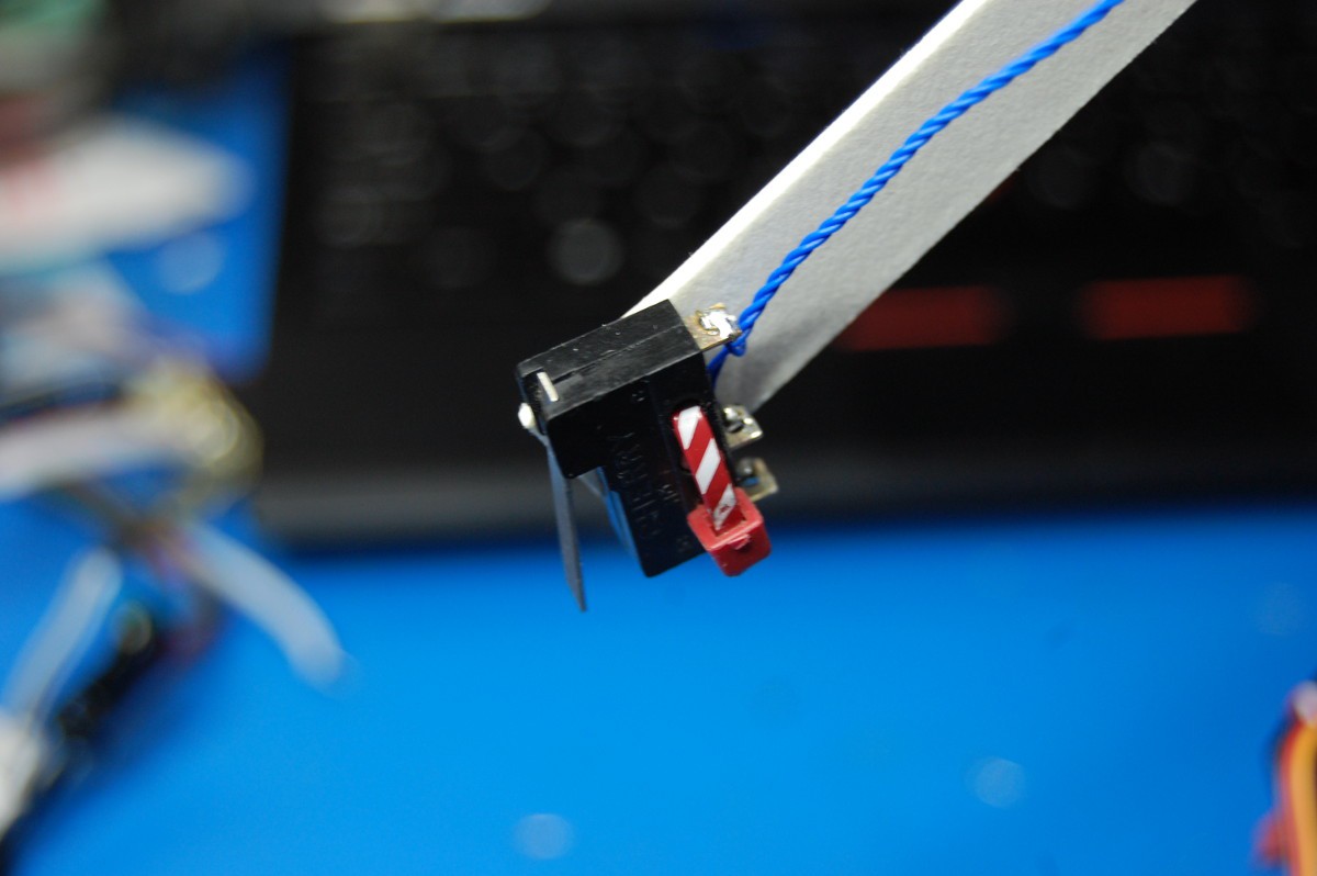
A shot of the new bump switches, installed along with the pulltruded CFRP "sensor bar":
[I call them elephants because the bent snap action switches look like they have little trunks.]![]()
Flip over the lid and... surprise plug! Sorry, had to do it:
![]()
Okay, that's it for now. I also took a bunch of pictures showing what goes into a simple [but surprisingly robust] brain for NeuroBuggy that I will post another day. In the meantime, here's a video of the robot finding its way out of an obstacle course built of of crap in my living room:
-
NeuroBuggy's Brain
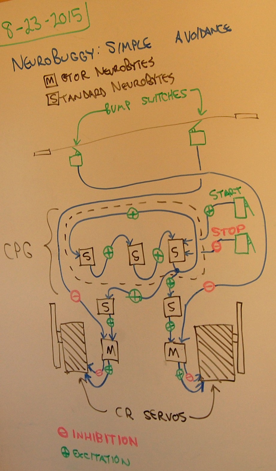
08/24/2015 at 00:08 • 0 commentsI'm not sure if this is the right way to do notation--open (always) to suggestions. In any case, this is how NeuroBuggy's brain was wired up for yesterday's video:
![]()
Hitting the START button kicks off the Central Pattern Generator (CPG), which runs continuously as a 3-NeuroBytes loop. The STOP button inhibits one of the members of that loop, causing the pulse to die after a second. Note that both of these switches are combined into a single double switch unit.
Once the CPG is running, an Axon Terminal (the blue ball at the lower right of the CPG) starts dumping pulses into another pair of NeuroBytes, which then feed into the two Motor NeuroBytes. The pulse generator operates quickly enough that the next pulse comes along before each Motor NeuroBytes board stops spinning its servo; thus, this circuit produces continuous rotation. The Motor NeuroBytes boards are actually mirror images of each other in firmware terms, so sending excitatory pulses to each one spins their respective servos in opposite directions (which ends up being 'forward', since they're mounted 180 degrees apart).
When one of the bump switches contacts an object in my living room, it immediately hits the inhibitory input of the opposite Motor NeuroBytes board. This overrides the last pulse seen by that board and causes it to spin in reverse for a short time, causing NeuroBuggy to rotate away from the object. Both servos start spinning in one direction once the next CPG pulse comes around.
To put this circuit into action, we start with a blank NeuroBuggy:
![]()
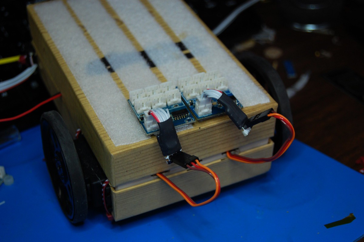
Starting from the drive end, we add the two Motor NeuroBytes:
![]()
... plug them into the servos:
![]()
... and tuck the excess wire back into the chassis:
![]()
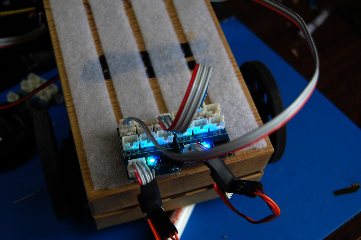
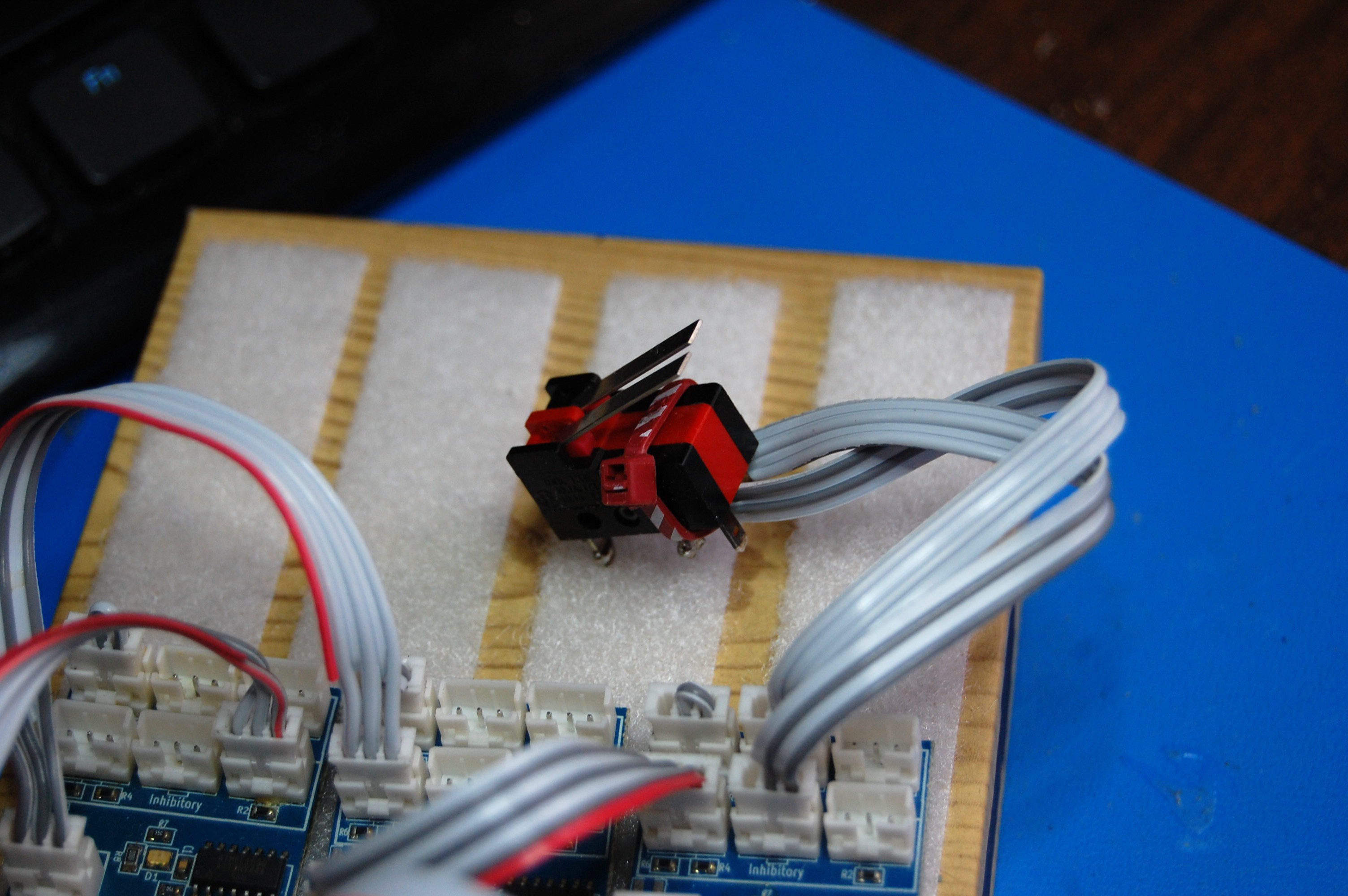
A quick test with an extra switch shows the Motor NeuroBytes are properly programmed (cyan = CR servo version) and working as intended:
![]()
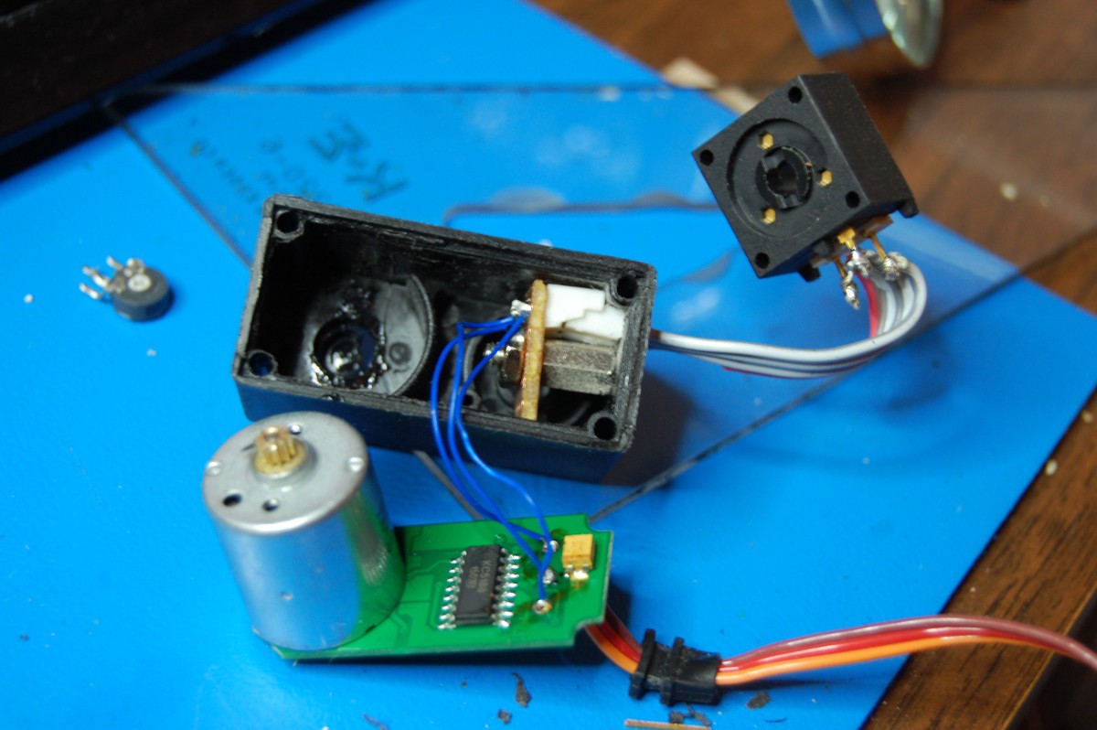
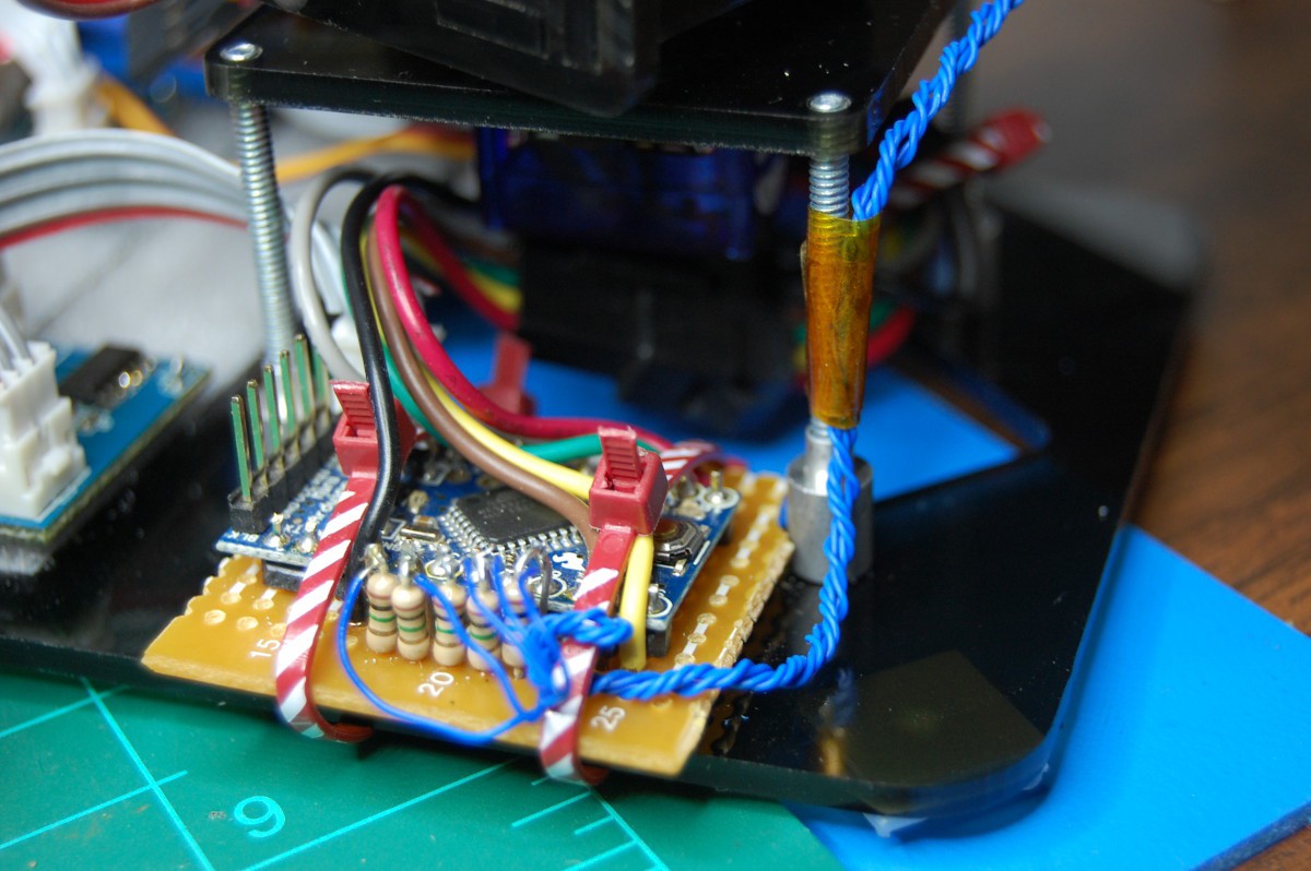
Now, since NeuroBytes are all a bit different (v0.4 uses the ATtiny44A's internal RC oscillator, so the 1-2 mS servo pulses aren't identical between Motor NeuroBytes boards), it's time to adjust the CR servo zero points. In the previous post, I turned around the servos so that the zero adjust pots were more accessible. This was still a pain (I kept pushing the board-mounted trimpots back), so I decided to mount external adjustment pots. Side project!
![]()
As you can see above, this got a bit more complicated. I used a standoff and a small piece of perfboard to mount a standard NeuroBytes connector in the servo case; this required a ton of trimming to clear the servo assembly screw post (which it barely does). Why the trouble? Well, the servos need to slide through a fairly tight rectangular hole in NeuroBuggy's chassis, and I didn't want permanently attached wires getting in the way. Also, the pots I happened to have around (which were 50k vs the 5k board-mounted unit shown in the picture above) were a bit big for internal mounting.
Once I tested the servo sans gearbox, I buttoned it up:
![]()
... pulled the pot out, installed the servo in NeuroBuggy, reattached and finally mounted the pot in the chassis:
![]()
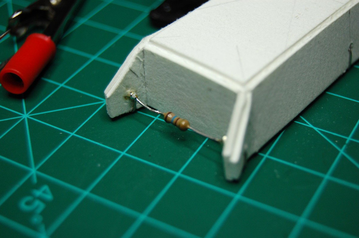
I made sure to carve a decent size hole in the chassis so the zero points were still adjustable:
![]()
[note: at some point I acquired a large quantity of 1/4 watt 160 ohm resistors that I have since never used. As such, when you see them in projects (like the four here) they're generally used for holding things together.]
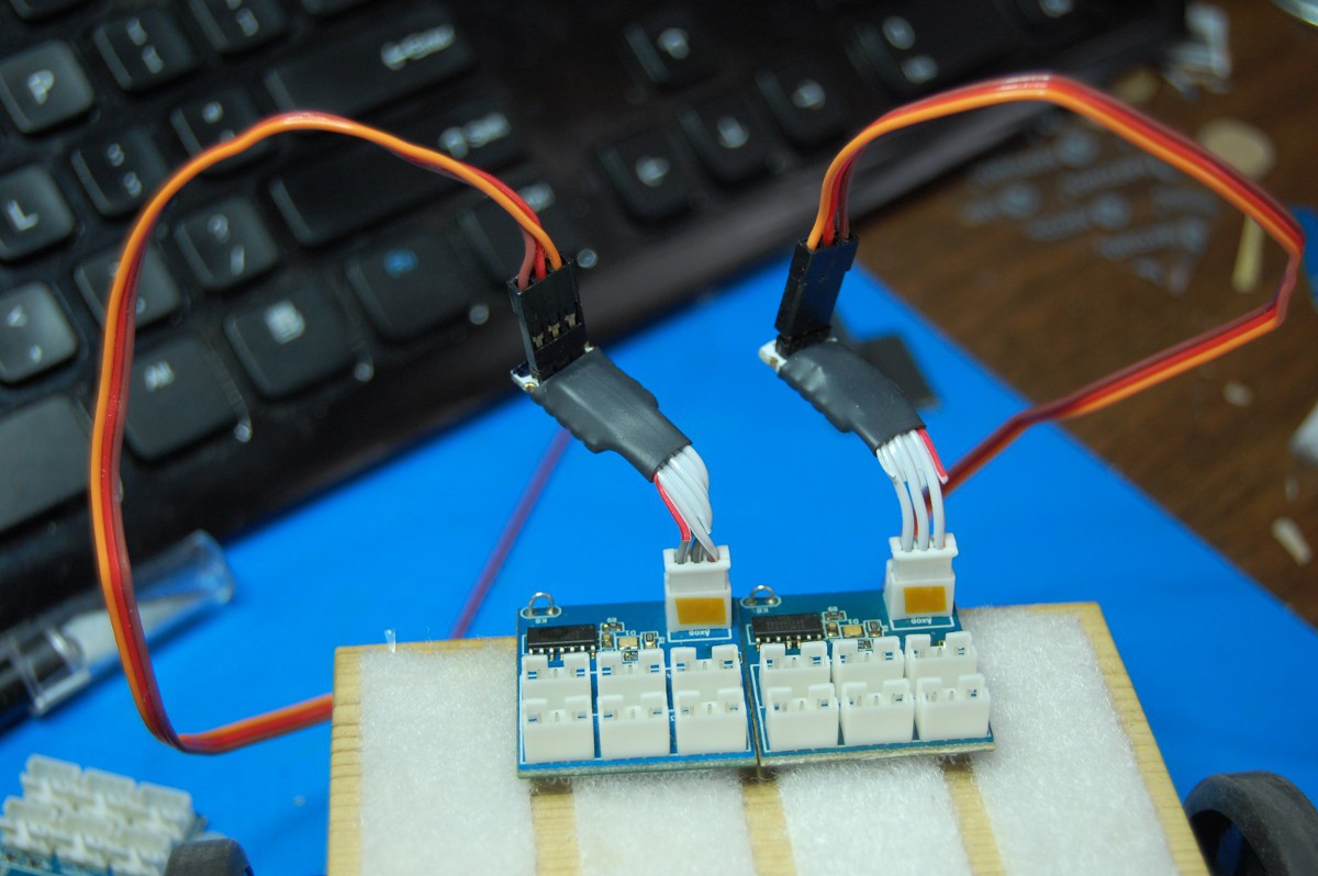
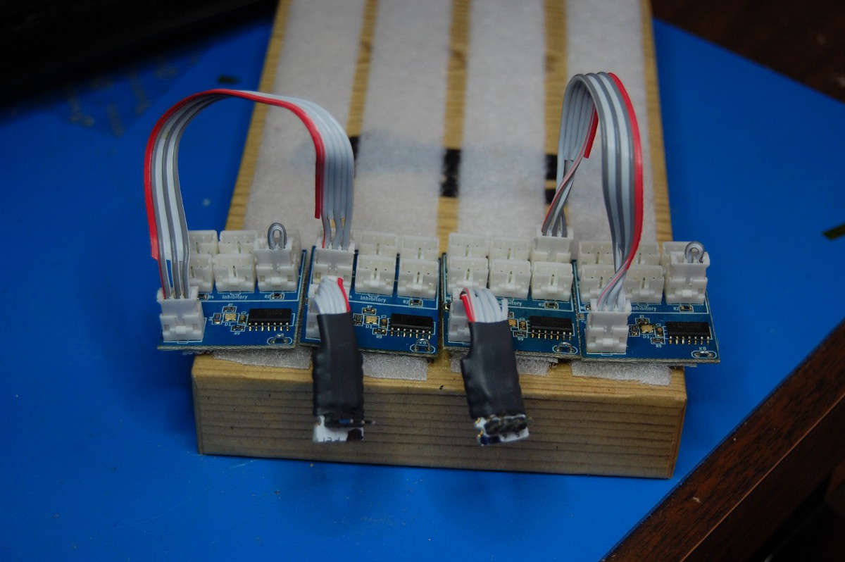
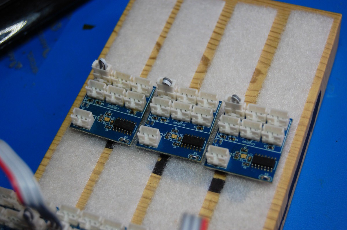
Okay, back to putting NeuroBuggy together. Next, it's time to mount the two NeuroBytes that feed directly into the Motor NeuroBytes:
![]()
To keep the images clear, I've temporarily removed NeuroBuggy's brain from its chassis. Notice that the axons on each of the NeuroBytes feed directly into the Motor NeuroBytes (opposite inputs in this case; this picture was prior to splitting the Motor NeuroBytes into CW and CCW versions). The two new NeuroBytes also have Exciters installed, so they'll fire an action potential if they see a single excitation.
Next, it's time to build out the 3-element CPG:
![]()
Again, these three NeuroBytes already have Exciters installed, so they'll trigger upon receiving a single excitatory pulse.
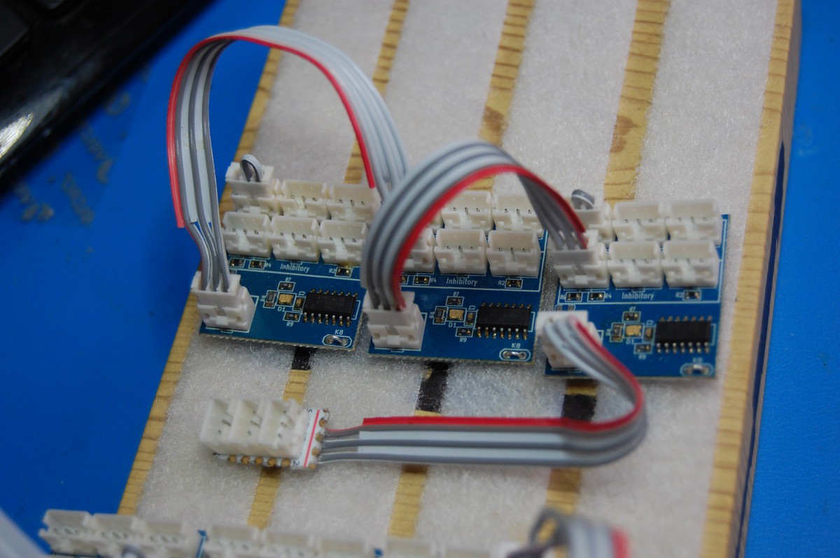
The CPG gets wired sequentially, with the last NeuroBytes board getting fed into an Axon Terminal:
![]()
This Axon Terminal then feeds back to the first CPG NeuroBytes board, along with both of the NeuroBytes that feed into the Motor NeuroBytes (and then the servos):
![]()
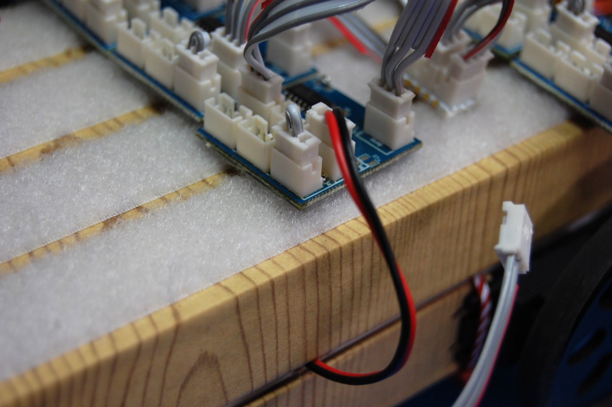
The START/STOP switch gets installed:
![]()
... and then the lid gets placed back on the chassis. This allows us to land the power and servo cables:
![]()
![]()
Finally, the two bump switches are fed (using extension cables) into the inhibitory/reverse rotation inputs in the Motor NeuroBytes modules (not shown in this poorly framed shot):
![]()
... AND WE'RE GOOD TO GO:
![]()
In case you missed the video, here it is again:
Simple, right? Don't worry--things can get a lot more complex, but that's for a different day:
![]()
-
Hey, what happened to "Neurons, Neurons, Neurons... "?!?
08/27/2015 at 18:42 • 0 commentsIf you've been watching for awhile, you know that this project started as "Neurons, Neurons, Neurons... "
So what happened?!? Well.. as discussed previously, @NeuroJoe and I formed NeuroTinker, applied for a few SBIR grants, met with a lot of educators and students, got a great logo/website designed, entered THP2k15 (and got ridiculously excited when we made it to the Best Product finals), etc etc--in any case, it was time for a formal product name.
NeuroBytes. Motor NeuroBytes, Sensory NeuroBytes, bundles of NeuroBytes mounted to a NeuroBuggy, NeuroBytes in the classroom, NeuroBytes hanging on the wall, all designed and built by NeuroTinker--starting to see a pattern? It's a great prefix!
Anyhoo, I've been told old hyperlinks still work, so the previous project URL will just redirect here.
-
Need more NeuroBytes.
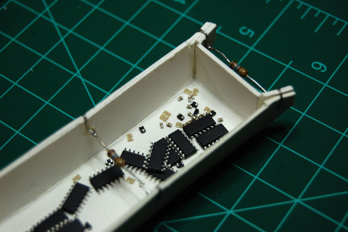
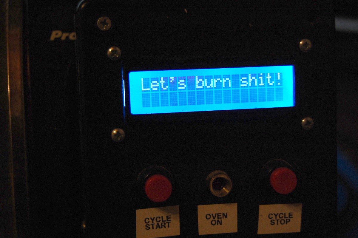
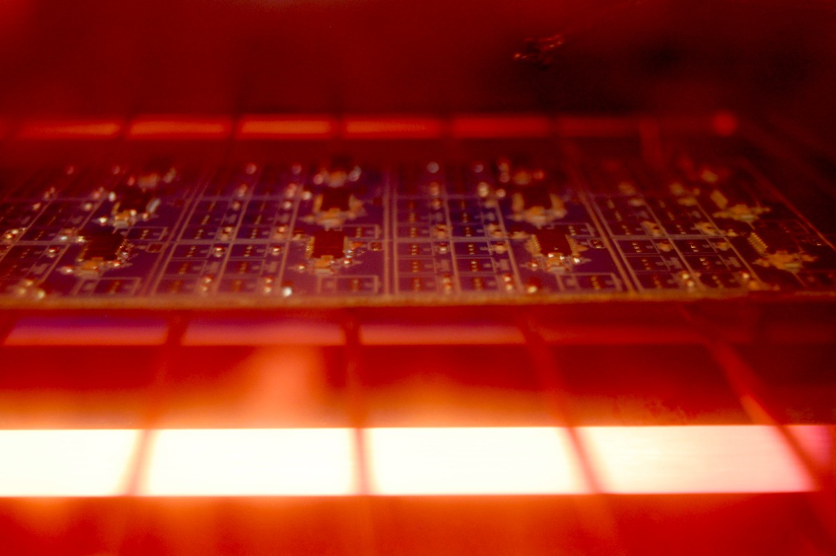
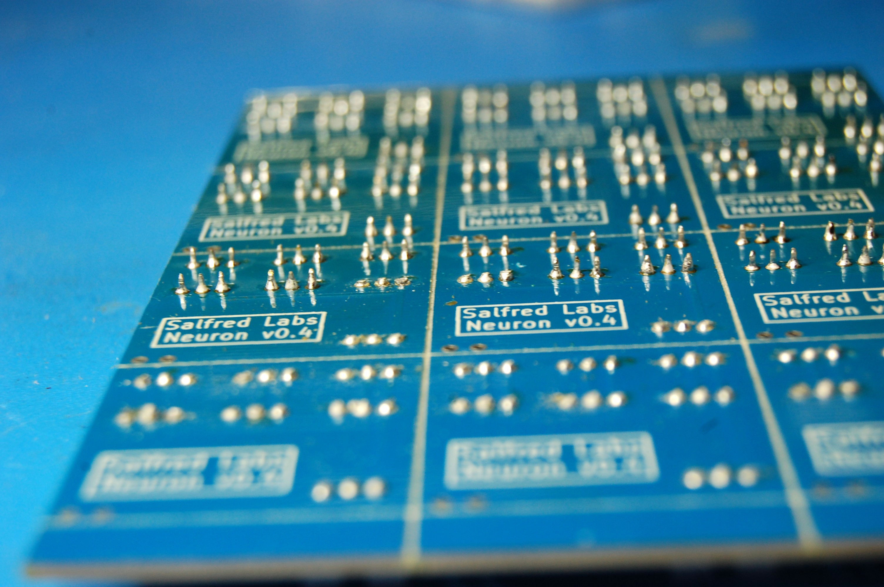
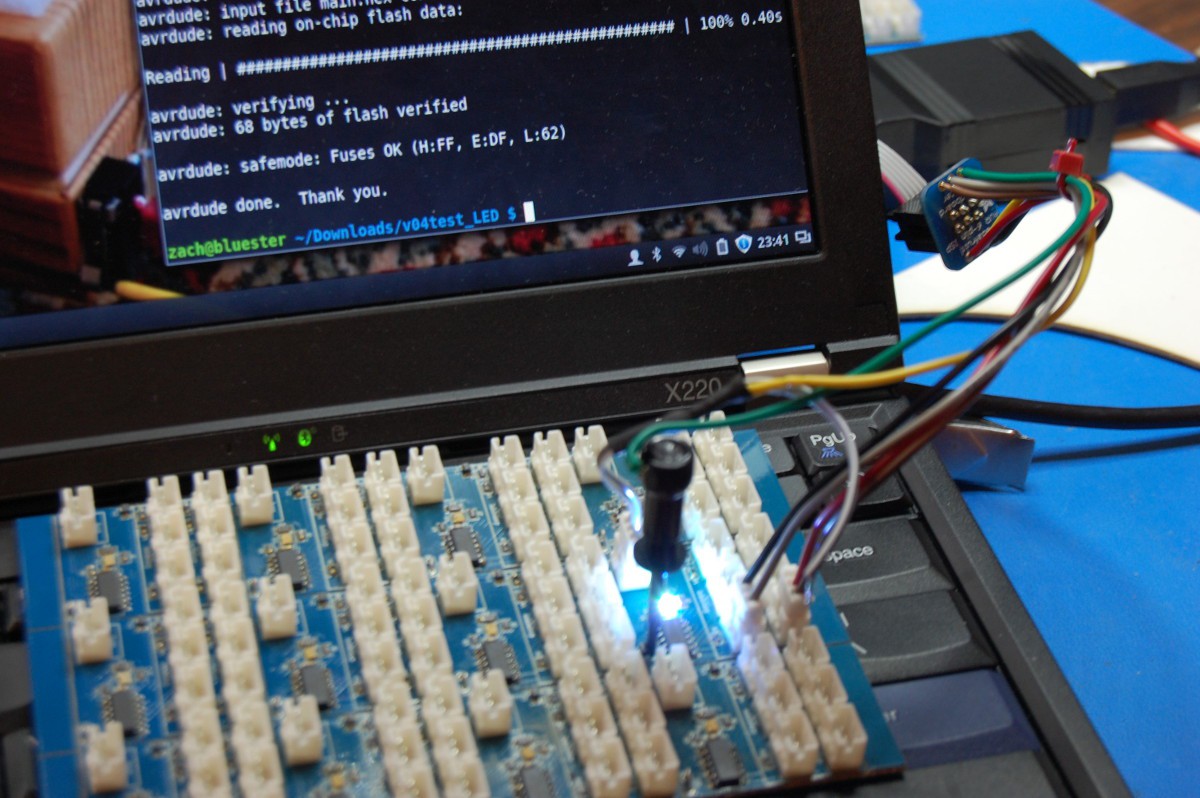
08/28/2015 at 05:24 • 1 commentI'm running low on NeuroBytes v04 components. I don't have an exact count, but I'm guessing I've built 100 or so boards to date. I hammered out another dozen tonight, and decided to document the process. I also distracted myself for awhile building a bin to hold SMD components (it's not a great design, as it lacks ESD protection).
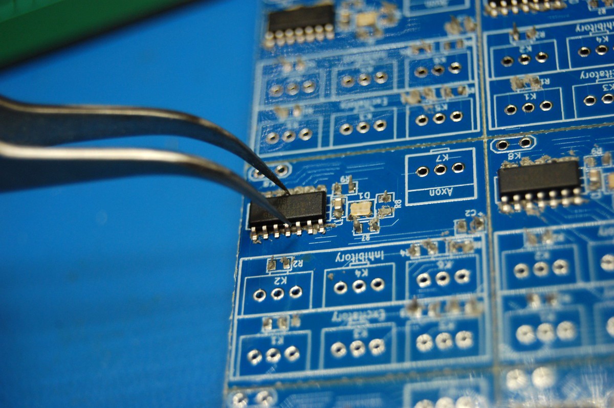
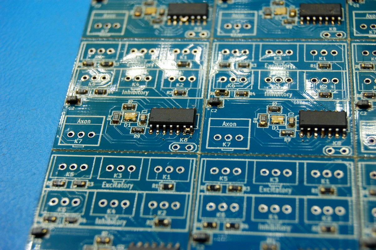
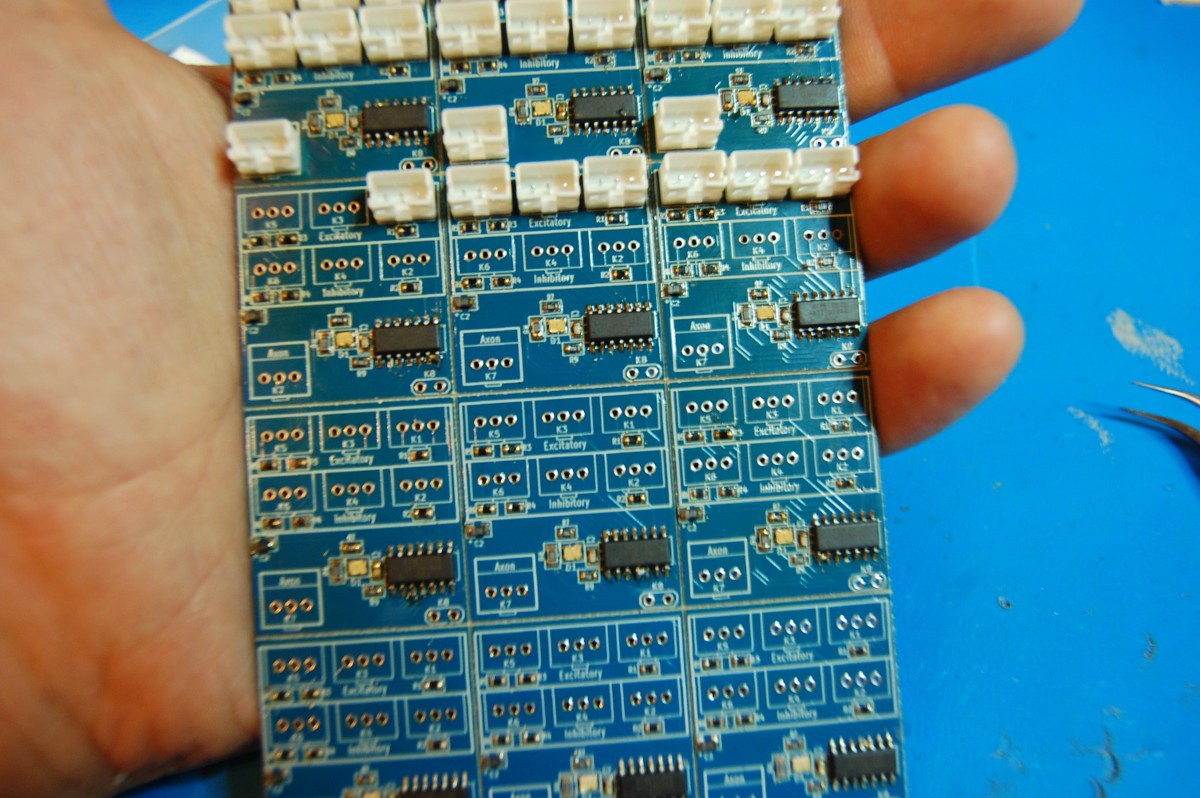
Special one-time bonus: no words, only pictures!
![]()
![]()
![]()
![]()
![]()
![]()
![]()
![]()
![]()
![]()
![]()
![]()
I went 12 for 12 after fixing six solder bridges. Not bad!
-
Neuro, uh, Arm? Also, updated servo firmware.
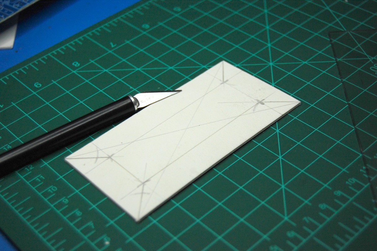
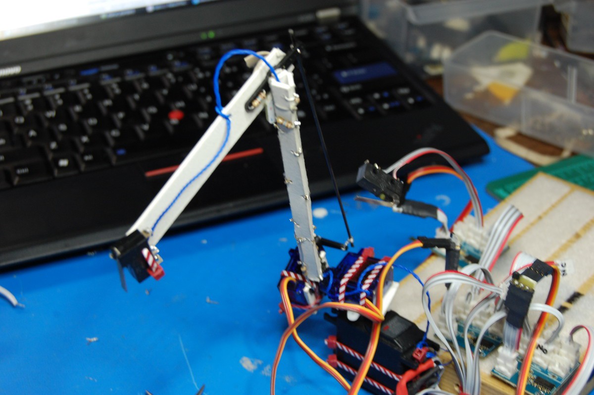
08/31/2015 at 03:38 • 0 commentsI engaged in a bit of paper- (matboard-) craft this weekend and built a little 3-axis arm onto the back of NeuroBuggy:
![]()
The whole thing is put together with zip ties, bits of matboard, a carbon fiber rod, three servos with their accessories, a snap-action switch, and a ton of 160-ohm resistors.
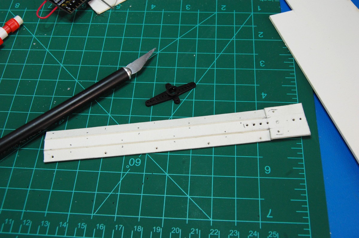
The upper portion of the arm, between the shoulder and elbow, are built out of a triangular section that mounts directly onto a shoulder servo:
![]()
![]()
![]()
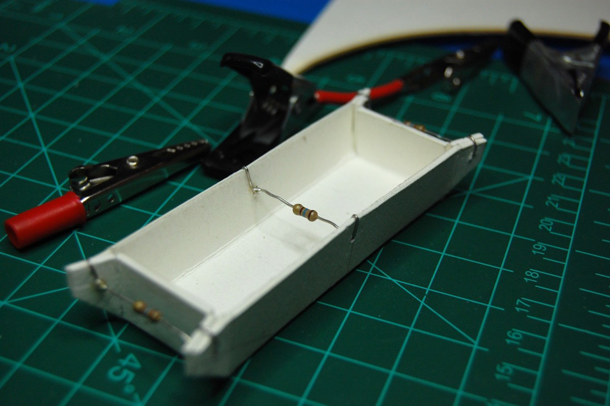
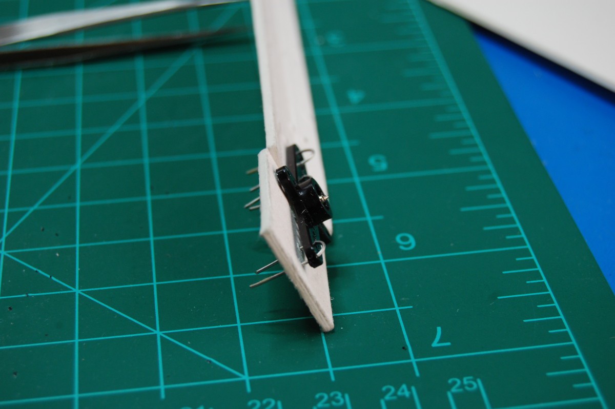
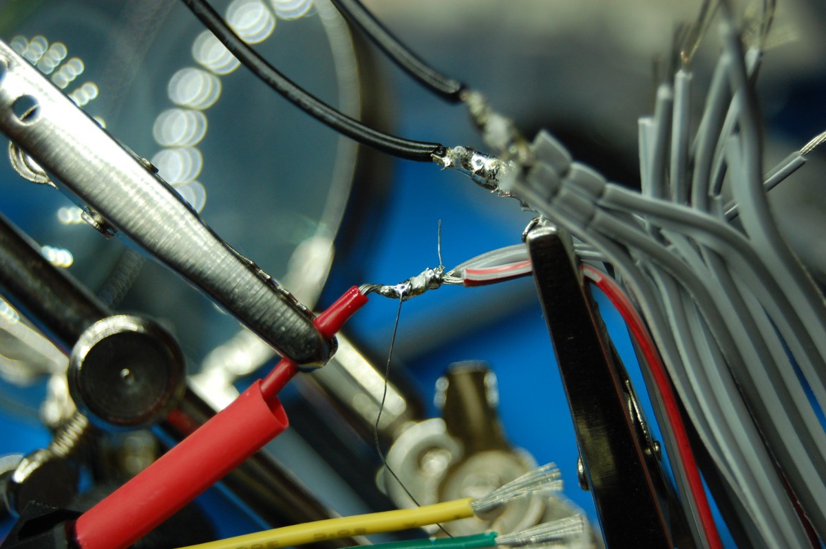
The elbow itself is made out of a piece of perfboard, a brass grommet that came with the servo, a servo horn, and a few bits of soldered together wire:
![]()
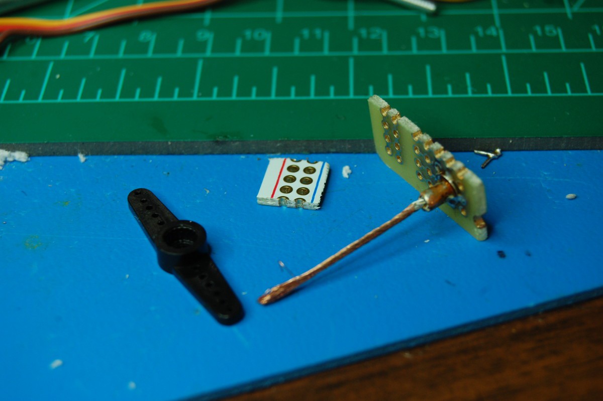
It goes together like this:
![]()
![]()
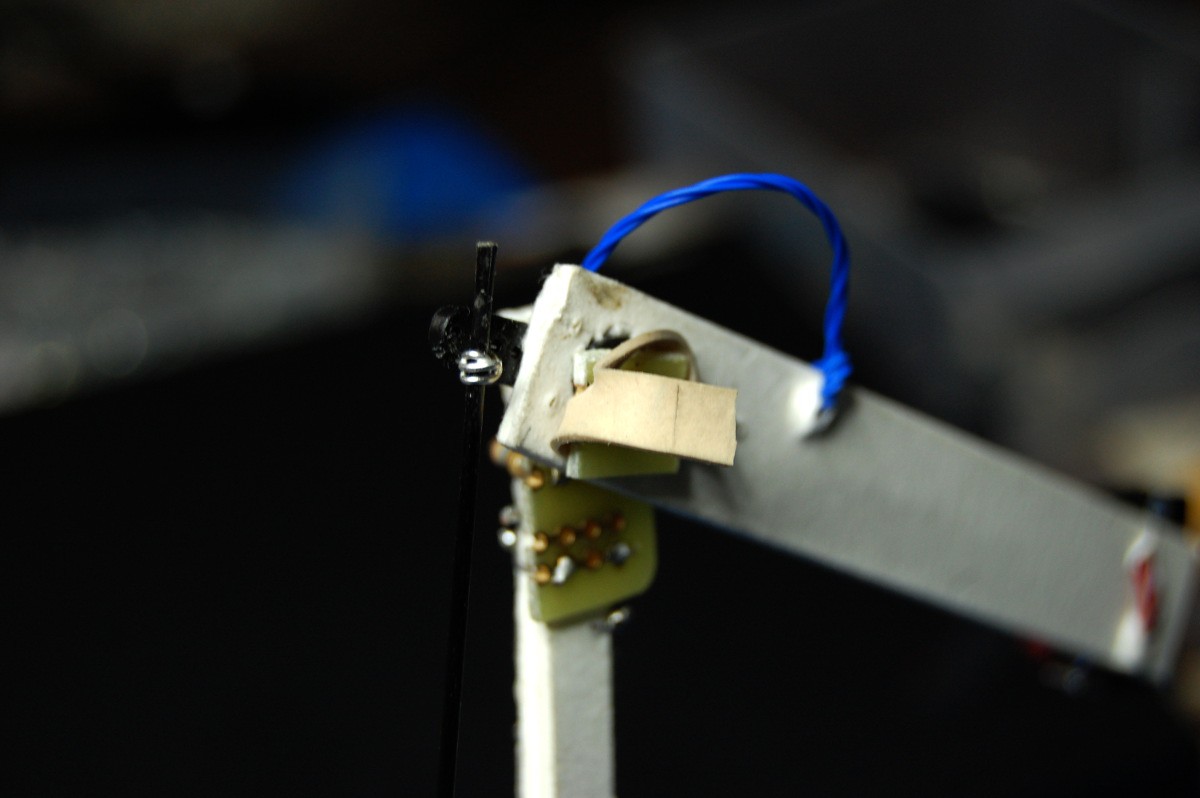
The joint had a fair amount of play (read: +/- 10 degrees), so I added a springy spacer made out of a bit of rubber band:
![]()
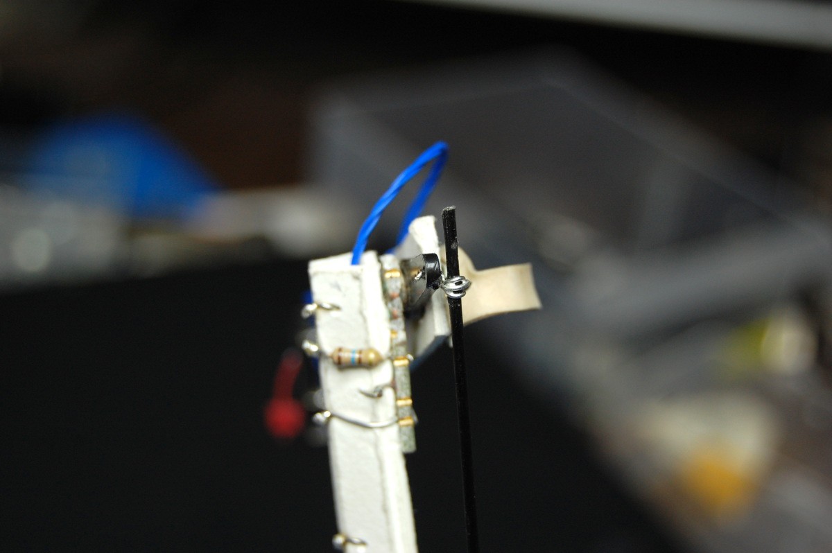
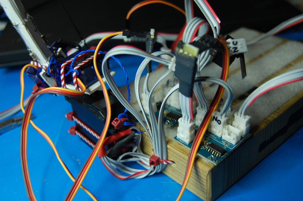
The wire runs to both the normally open and normally closed terminals of a snap action switch:
![]()
The pulltruded CFRP rod attaches to a servo mounted on the elbow:
![]()
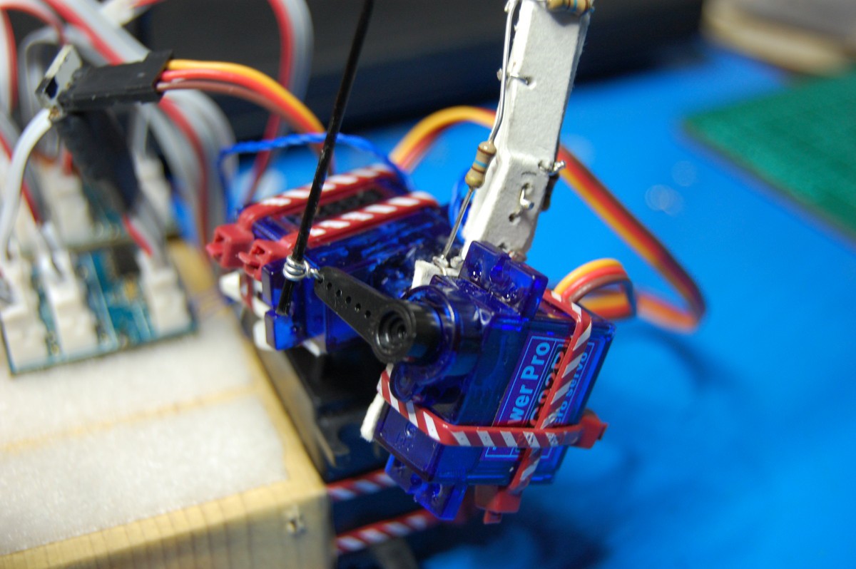
On the other side of the elbow, you can see the (slightly undersized) direct-drive shoulder servo, along with the rotation servo:
![]()
I soldered together a breakout cable that doubles both the N.O. and the N.C. switch contacts, then used zip ties as strain reliefs:
![]()
I also pushed an update to the GitHub repo that adds new functionality to the non-continuous-rotation servo firmware. The new code is in NeuroBytes-v04/FIRMWARE/v04run_servo-std. It's called this because the code is derived from the standard NeuroBytes runtime firmware, "v04run_standard". Changes vs the other servo drivers:
- LED color is now yellow to differentiate from the other non-continuous-rotation servo code (magenta) and CR code (cyan).
- Dendrites are now scaled from left to right, 1x-2x-4x, inhibitory/excitatory as labeled. x is an arbitrary value that represents something like 10 degrees rotation (so a single hit on the upper right dendrite will cause 40 degree rotation).
- Servo angle is now relative, not absolute! In other words, the current angle "decays" back to 50% of the servo range and is modified as inputs hit various dendrites. It's pretty much the standard v04 runtime firmware, scaled a bit to work with a servo and modified so that the current membrane potential directly feeds the servo angle. Also, "firing" doesn't happen. Make sense?
I then wired the touch switch to the 2x inhibitory (i.e. pull-back) inputs of both the elbow and the shoulder Motor NeuroBytes:
Pretty neat, eh? Unfortunately (and predictably), the arm structure is getting damaged by the constant back-and-forth motion, particularly around the shoulder connection. I got concerned about its integrity before I had a chance to add addition sophistication to the neural circuit (such as integrating the touch sensor into NeuroBuggy's drive circuitry). However, I'm hoping to rebuild the arm out of more resilient materials sometime this week.
-
Check out NeuroBytes. Cambridge, MA. Labor Day.
08/31/2015 at 14:27 • 0 commentsWant to know why I've been on a NeuroBytes/accessory building rampage this month? THP2k15 has something to do with it, but we're also accelerating the rate at which we show the product to other people. Because, you know, feedback.
One of the SBIR grants we've applied for is called Serious STEM games. The aim of the grant is to develop fun educational games for the K-12 market. As such, "gameifying" NeuroBytes is high on our priority list. The Game Makers Guild has agreed to take a look at what we've done and wants to give us suggestions to make the product more fun and engaging!
So: if you happen to live in New England, and are interested in the NeuroBytes project, and don't have have plans on Labor Day (next Monday, 9/7, 6:30 PM), you should drop by. @NeuroJoe will be on hand to show off what we've got. It's free and open to all, but you must RSVP!
-
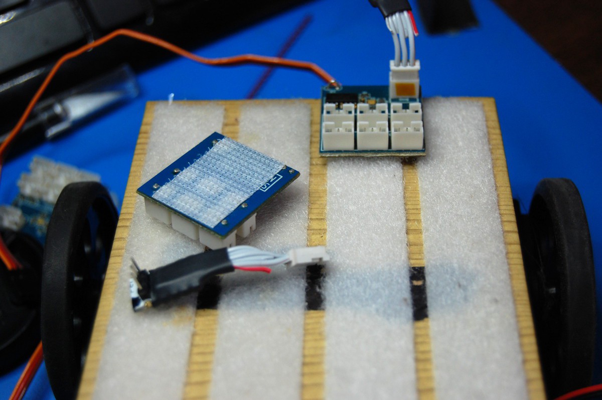
Capacitive Touch
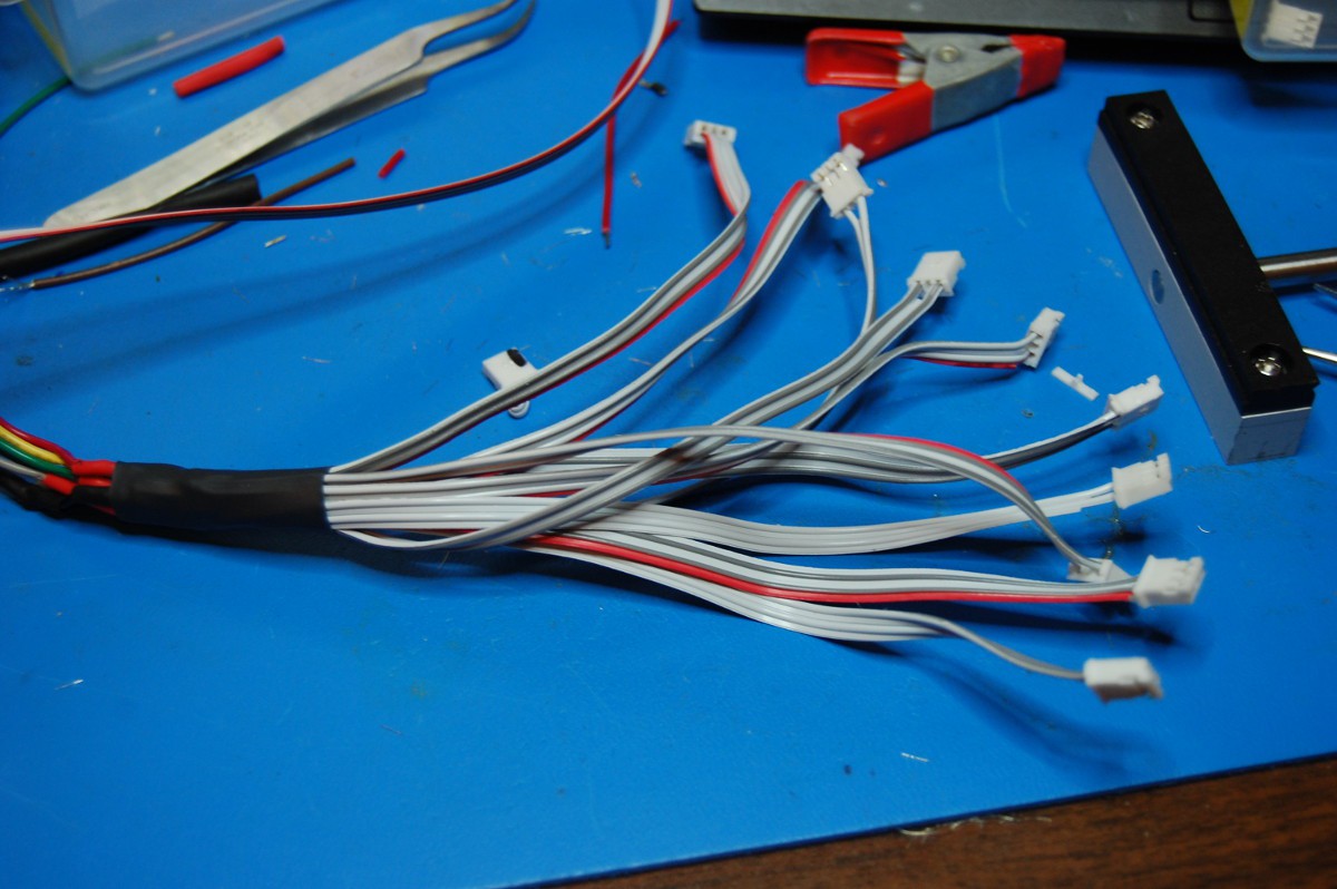
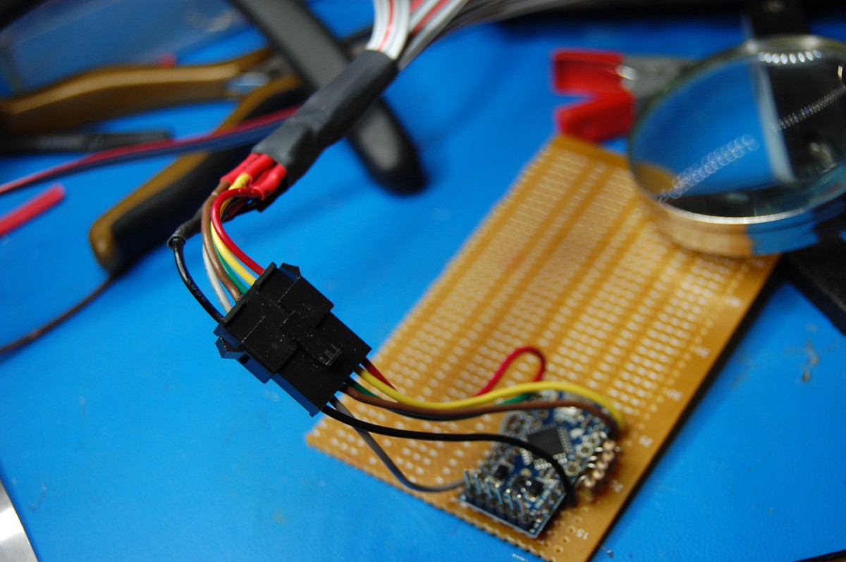
09/02/2015 at 03:38 • 0 commentsI used an Arduino Pro Mini along with the CapacitiveTouch library to build a 5-channel touch-to-NeuroBytes sensor board (with two NeuroBytes-compatible outputs per channel). The adapter comes in two parts, the board and the harness:
![]()
![]()
![]()
I haven't connected any sense wires yet, but after randomly linking them to various Motor NeuroBytes attached to the 3-axis arm, I was able to get a bit of movement:
The code is fairly trivial; if you're curious, I pushed it to the GitHub repo under /Firmware/v04_touch_input_PM (for Pro Mini). More to come!
-
NeuroBytes + MeArm + 5ch touch sensor
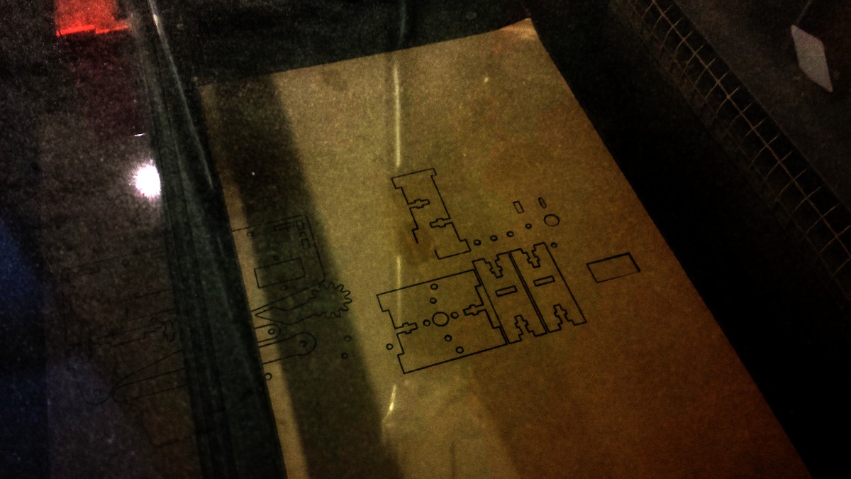
09/03/2015 at 04:48 • 0 commentsMy awesome wife has a laser cutter at work. I dropped by Monday evening with a sheet of dark acrylic and she cut me a #MeArm!
![]()
I happened to grab the files for version 3, but I understand there are newer models out there now. In any case, it went together nicely and lined up nicely with my next order of micro servos arriving. UPS had a bit of a snafu with my hardware order, so I had to scrounge around quite a bit at Home Depot (and completely cleared them out of M3 hardware). Other than some longer-than-necessary-and-not-trimmed bolts, everything worked out. Okay, I cracked some of the acrylic around the gripper. Still works.
Instead of installing a microcontroller, I applied a bunch of fuzzy Velcro to the base. I also installed the previously discussed touch sensor board under the pedestal:
![]()
I used a roll of sticky copper tape to create touch panels along various MeArm structural elements. Interconnections happened using blue wire wrapping wire (which will probably fail due to metal fatigue at some point) soldered onto various panels. In some cases (namely C and D), two panels are also bridged into one input:
![]()
![]()
Then I hooked up a few NeuroBytes: three Motor NeuroBytes for three of MeArm's axes (I didn't hook the gripper up as I still need to fabricate a fourth servo adapter) that handle servo control and reflexive motion, and a handful of standard NeuroBytes to add some simple behavior:
![]()
As usual it's a jumbled mess, but it does look better in the dark:
![]()
Video showing said simple behavior (note the 'frustrated shake' when I touch the back of the arm too many times):
It goes without saying, but if you don't already have a #MeArm you should change that immediately. Made for a thoroughly enjoyable evening of building and wiring, and it's hilarious to watch to boot. Probably would be a lot less jerky with a proper controller, too.
-
Details section pre-9/10/2015
09/11/2015 at 02:05 • 0 comments[This was the original Details section, modified a number of times since its initial creation with the project. This section dives into the project history a bit more than the current document, but is also a bit disjointed and out-of-date.]
WE MADE THE 2015 BEST PRODUCT FINALS! WOOOOOOOOOOOOOOOO!
[UPDATES 8/12/2015: https://hackaday.io/project/3339-neurons-neurons-neurons/log/22629-neurotinker-grants-progress-excitement-etc and https://hackaday.io/project/3339-neurons-neurons-neurons/log/22643-patellar-reflex-model]
Background
Lots of background for this project. I'm publishing this after 9 months of work, so there is some catching up to do. Okay, to be fair... 3 months of work, then 6 months of nothing (Andrew moved to NYC and Zach switched focus to GimbalBot).
First, let's get this out of the way: a word on why this is getting published in December rather than February of 2014. Andrew and I went back and forth many times on commercialization, and we weren't quite ready to share the project last spring. We considered trying to build a product, protect our intellectual property, and pursue the educational market as a company. Eventually, we concluded that defining the project as Open Hardware is the best path forward regardless of eventual outcome When the collaboration with @NeuroJoe started in early 2015, he agreed with this philosophy too. As such, Neuron firmware and hardware design documents are licensed under the GNU GPL v3.0.
As covered briefly in the introduction, Andrew and I had brunch with a few friends in early 2014. He'd been learning about neuroscience--he found the subject absolutely fascinating--and had written a plugin for Google Sketchup that allowed one to create neural networks on the fly, and then simulate their activity and response to various stimuli. In the screenshot below, the green and red boxes are neurons; the black lines are interconnections; color indicates level of excitement:
![]()
The program was fun to play around with and had a tendency to produce unexpected outcomes, especially when large quantities of neurons were linked together in a random fashion. I asked Andrew to write a bit about this phase of the project which I've pasted below:
Whatever the motivation, I wrote a program in Ruby using the SketchUp API that would generate a random butt of 'neurons.' I didn't want the code to execute all at once, and I wanted it to step slowly enough that I could watch it, so I wrote an environment that would keep track of each 'neuron,' its upstream and downstream connections, and the messages it was sending. I then had the environment generate a model of the neurons in the SketchUp environment so that I could see the connections, and I had it color the neurons according to their potential. By allowing the environment to progress one step, every neuron's input was summed, checked against its internal threshold, and if the potential (sum of inputs) was greater than the threshold, a message was sent to all neurons downstream.
Neither of us are neuroscientists--I'm a materials science engineer by training, and Andrew is an architect. After talking over brunch and seeing the simulation, we decided to work together to build something physical. Our main goals were to make it modular, cheap, and fairly accurate to real life. We've come pretty far since then (with a healthy summer break), so I'm going to start by trying to organize the project history in chronological order.
Neuron Development: v0.1, the Sketchup plugin
Neuron Development: v0.2, Pro Minis + Neopixels
Neuron Development: v0.3, many small improvements
Neuron Development: v0.4, time to scale up production [CURRENT]
Neuron Development: v0.5, just planning for now [FUTURE]
Part 2, Late Night Whiteboard Rambling
An extremely brief video outlining the basics of how typical real-life neurons work:
Plan for the latest Neuron, v0.4:
Neuron v0.4 quick overview (features, burning firmware, etc):
A simple 22-element loop, self-extinguishing after four pulses:
Patellar reflex model:
NeuroBuggy beats an obstacle course: