 Carl Bugeja
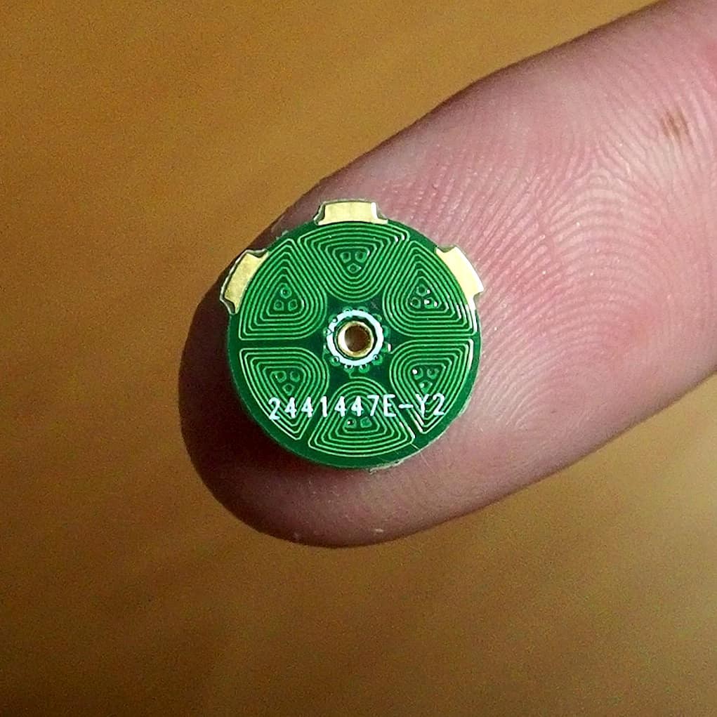
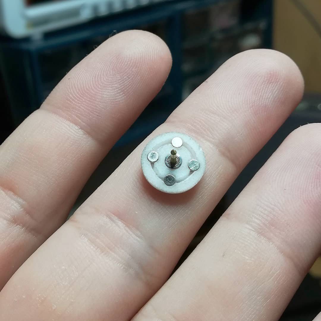
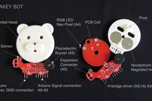
My PCB-Motor is made from a 6-pole stator printed on a 4-layer PCB and a 4-pole 3d printed rotor. Its has an outer diameter of 16mm and is rated at 1 watt.
I had this idea when I was trying to design a small compact drone. The PCB motor is much cheaper than other micro brushless motors and also easier to assemble. My goal is to make the rotor part of the BOM and mounted just like any other component on a PCB.
VIDEO
HACKADAY SUPERCON DEMO


 Jithin Sanal
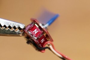
 ebaera
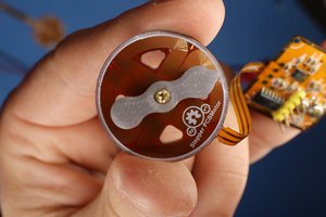
Hey Carl, great project. I am working on prism laser scanner with a BLDC motor see https://hackaday.io/project/21933-prism-laser-scanner . What kind of weight can you spin with this rotor? How planar is the rotation? The most important requirement is that the prisms stays flat and does not wobble during rotation. The size of the prism, depends on the application.