0%
0%
2Wire (I2C) From Blocks of Light on an LCD Screen
2Wire (unidirectional I2C) coms from HTML5 to hardware via blocks of light on the screen.
 James Newton
Become a Hackaday.io member
Already have an account? Log in.
Just one more thing
To make the experience fit your profile, pick a username and tell us what interests you.
Pick an awesome username
hackaday.io/
Your profile's URL: hackaday.io/username. Max 25 alphanumeric characters.
Pick a few interests
Projects that share your interests
People that share your interests


 platis.solutions
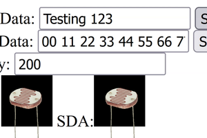
 Blecky
For example, if someone says, "As stated on page 10 of the report," it means that the specific information being discussed can be found on the tenth page of the mentioned report. https://techzone-agency.com/