-
1Step 1
DIssasambly
At first I dissasambled the Display to get rid of the back Metal cover.
Sorry but i don't have any Pictures of these Steps
-
2Step 2
Cut the Wires
So in the next Step i had to cut the Main Wire to connect it to the Standard Plugs and get it to work..
-
3Step 3
Rebuild Wiring
Table for Wiring HDMI /DVI to ADC
Then there is USB and Power, but i think the colors are standard, so I will not explain it here how to connect them.
Connecting the USB is optional
I didn't used the internal USB-HUB because its just an USB1.1 HUB.
But for Powering the PI and the tiny amplifier I directly wired the powerlines of the PI to the USB Ports of the Display.
One major Problem is the Powersource. :( the USB 1.1 standard causes the PI to reboot if there are to many USB devices connected to it, and i haven't found a proper Solution yet.
-
4Step 4
Powerlines of PI
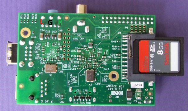
To directly wire the Pi into the Powersystem of the Display i used those spots to connect it :
![Direct connection of 5V to Raspberry Pi without micro-USB connector]()
The image above shows the way this should be achieved - the red wire for the positive 5V input, and the black wire for the negative/ground input. The positive wire connects to the reverse polarity protection diode, and the negative wire to the fuse, both of which remain fully functional with this wiring method.
The wires used should be good quality multi-stranded cable rated to carry at least 1 Amp. 7/0.2mm (7 strands of 0.2mm) cable is the minimum requirement. Check the insulation along the length of the cable very carefully to ensure that there are no holes in it which could lead to short circuits on the underside of the board. And shield the PI completely on the wireing side for shorts if you will mount it into Diplay like I did. -
5Step 5
-
6Step 6
Make it controllable
I just connected a MCE IR Remote via USB to the PI and it works out of the box with Openelec or Rasplex.
As for "design"-reasons i dismantled the IR Receiver and taped it in a Foot :D
And its better for receiving if the TV is mounted to the Wall
-
7Step 7
Make it talk
I used this tiny 2x3W Amplifier
As you can see in the pictures I connected it to an old USB cable ( just black and red for PowerSource )
And as Speakers i used some old MacBook Internal Speakers which have been connected directly to the AMP-PCB.
To connect the Amplifier Board to the PI you could eather use and 3.5mm Headphone Plug or solder it directly to the PI like this :
![]()

Discussions
Become a Hackaday.io Member
Create an account to leave a comment. Already have an account? Log In.