 Kumar, Abhishek
Read the story behind the concept on my blog here
As of now, I'm done with the schematics and currently routing the PCB for the cape. Once I get a working prototype, I'll publish more details.
A cape for the BeagleBone Black using readily available replacement spare TFT Panels and capacitive touchscreen originally used in tablets
Already have an account? Log in.
To make the experience fit your profile, pick a username and tell us what interests you.
Read the story behind the concept on my blog here
As of now, I'm done with the schematics and currently routing the PCB for the cape. Once I get a working prototype, I'll publish more details.
While searching for compatible displays I could use with the cape, I happened to stumble upon 7" 1024x600 LCDs as well, that used the same 50-pin layout and TTL interface. Nice. Then I see that one of the models I was viewing was IPS, and that grabbed my attention. IPS panels are so better than normal displays in terms of color reproduction and viewing angles than the TN panels commonly found. My mobile, tablet and PC monitor are all IPS and it does really make a difference.
I ordered the panels which arrived here shortly. Besides the TFT I also ordered a touch panel and a HDMI driver board based on the RTD2660 for this display so that I could also use it with my PC.
The touch panel they gave is on the FT5406 controller (unlike the FT5306 previously), same driver but unfortunately different pin layout, so will need to use some jumper wires.
Adjusted the LCD timings in the device tree after studying the panel datasheet, and it worked in the first attempt. Appearance wise though, it looks almost the same physically but that's where the similarities end.
As an aside, I also got 40cm long flat cables when I went shopping for some extra cables, initially wasn't sure if signal integrity would get messed up but was happy to see no visible distortion; the display works good even over these long wires.
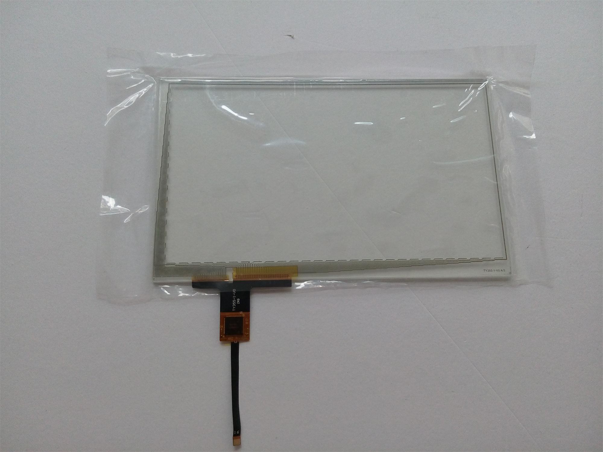
This touch panel has an acrylic front lens instead of glass.
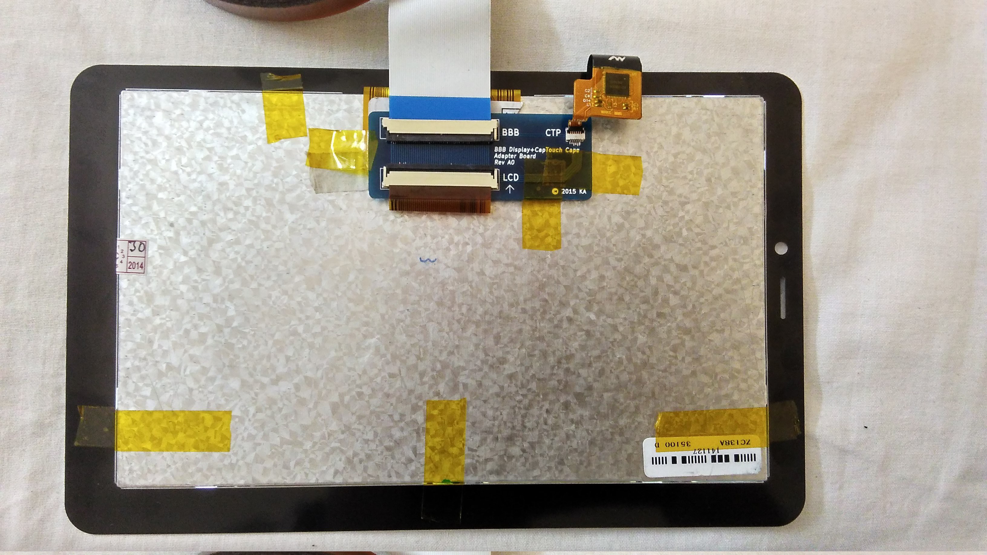
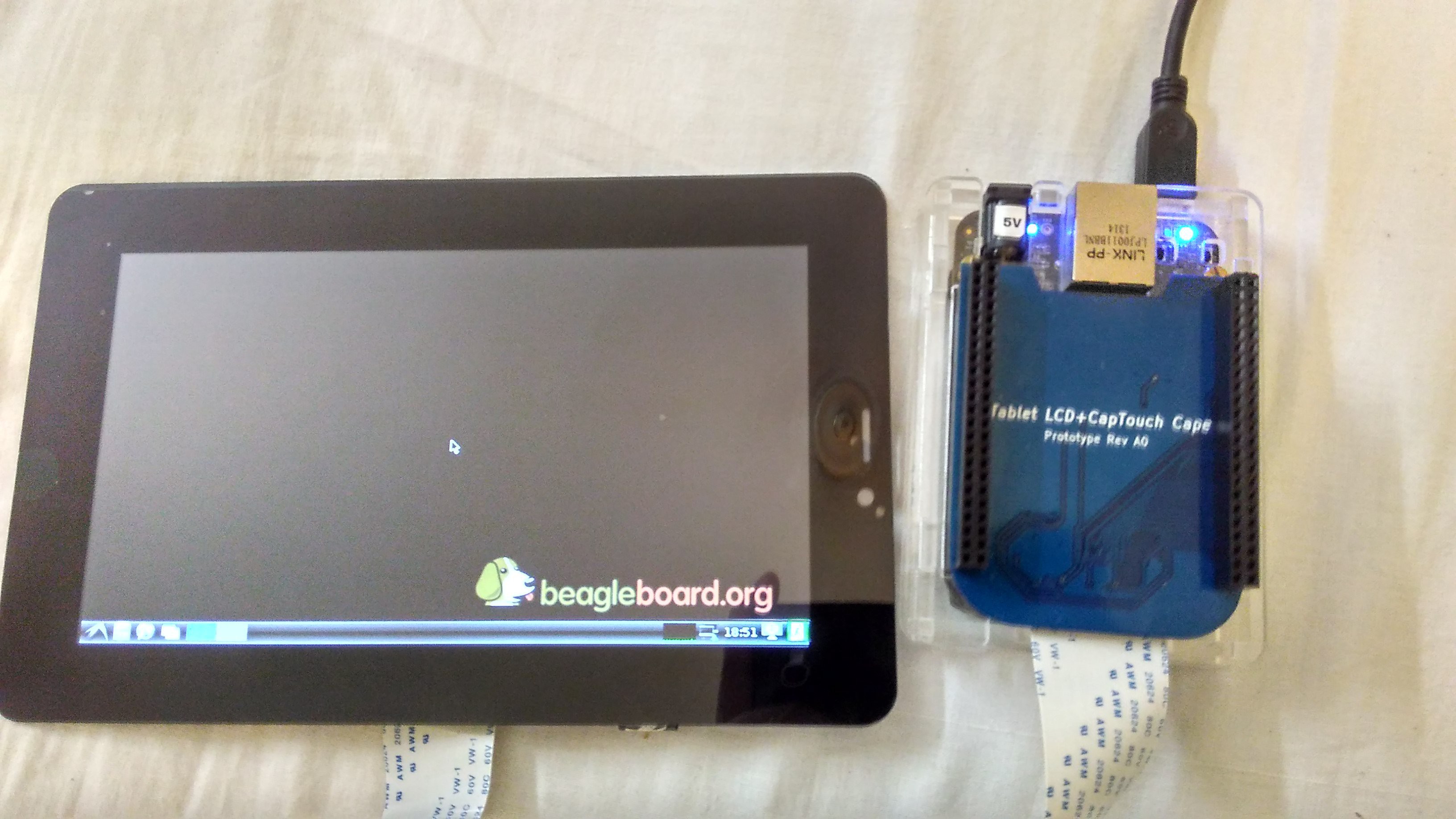
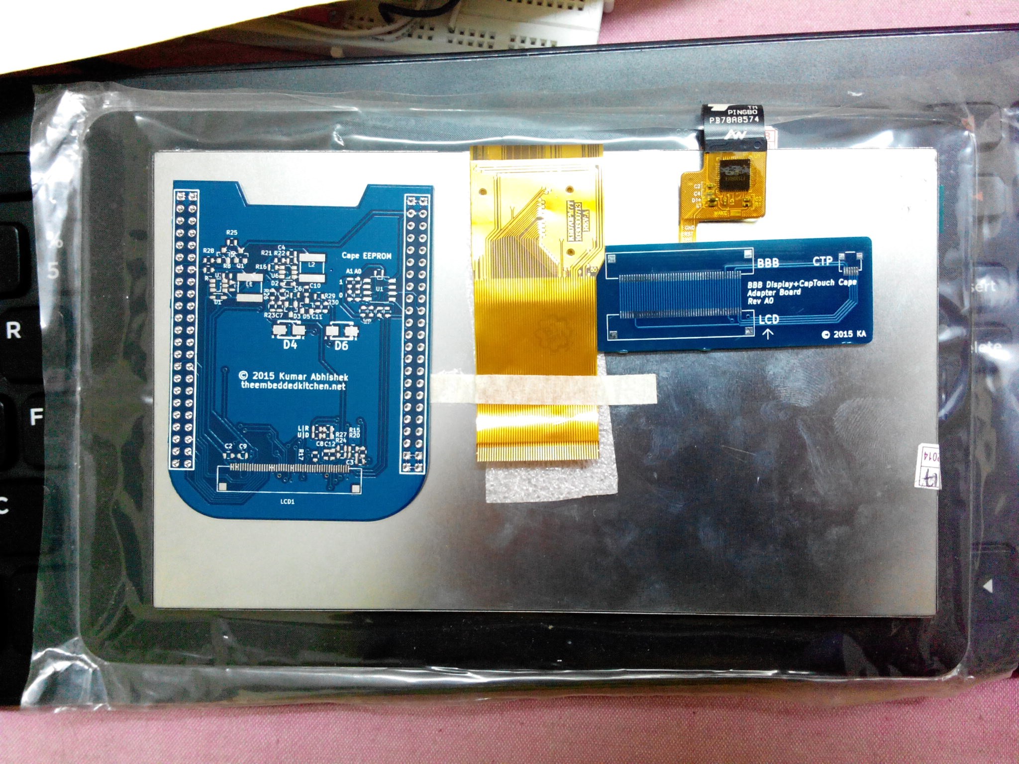
After fiddling with the device tree, the LCD and the touchscreen have been working nicely with the BeagleBone Black now. So I thought it was time I put everything together.
The touch panel (a new piece) is covered by plastic film on both sides. The first step was to go to a nearby cell phone shop and get a screen protector film over the top of the touch panel (Gorilla or not, I always like to place a film over the screen of all my devices, better to scratch a cheap replaceable film than the glass). The touch glass on the replacement panel has a thin strip of 3M double-sided tape for gluing it with the display, which is good. I just need to align the panel with my LCD screen well.
For the alignment process I decided to do several mock alignments before actually taping the display down. Turned the screen all-white and carefully placed the touch panel on top of the screen, making sure the bezel is aligned on all 4 edges. All-white screen means it is very easy to detect dust particles which shouldn't be there in the process. Repeated the mock-alignment several times before peeling off the protective film on the LCD. so warranty is now void! [ Note: It is usual practice for replacement parts to come with seller warranty if it is incompatible with your device, provided the protective films are intact ]. Peeled off the film on the back of the touch panel and the double-sided tape and carefully lowered it onto the LCD. Firmly pressed on all sides, and the panel is now "taped down" to the display.
Added some more tape on top to protect from double tape adhesive failure (which is unlikely).
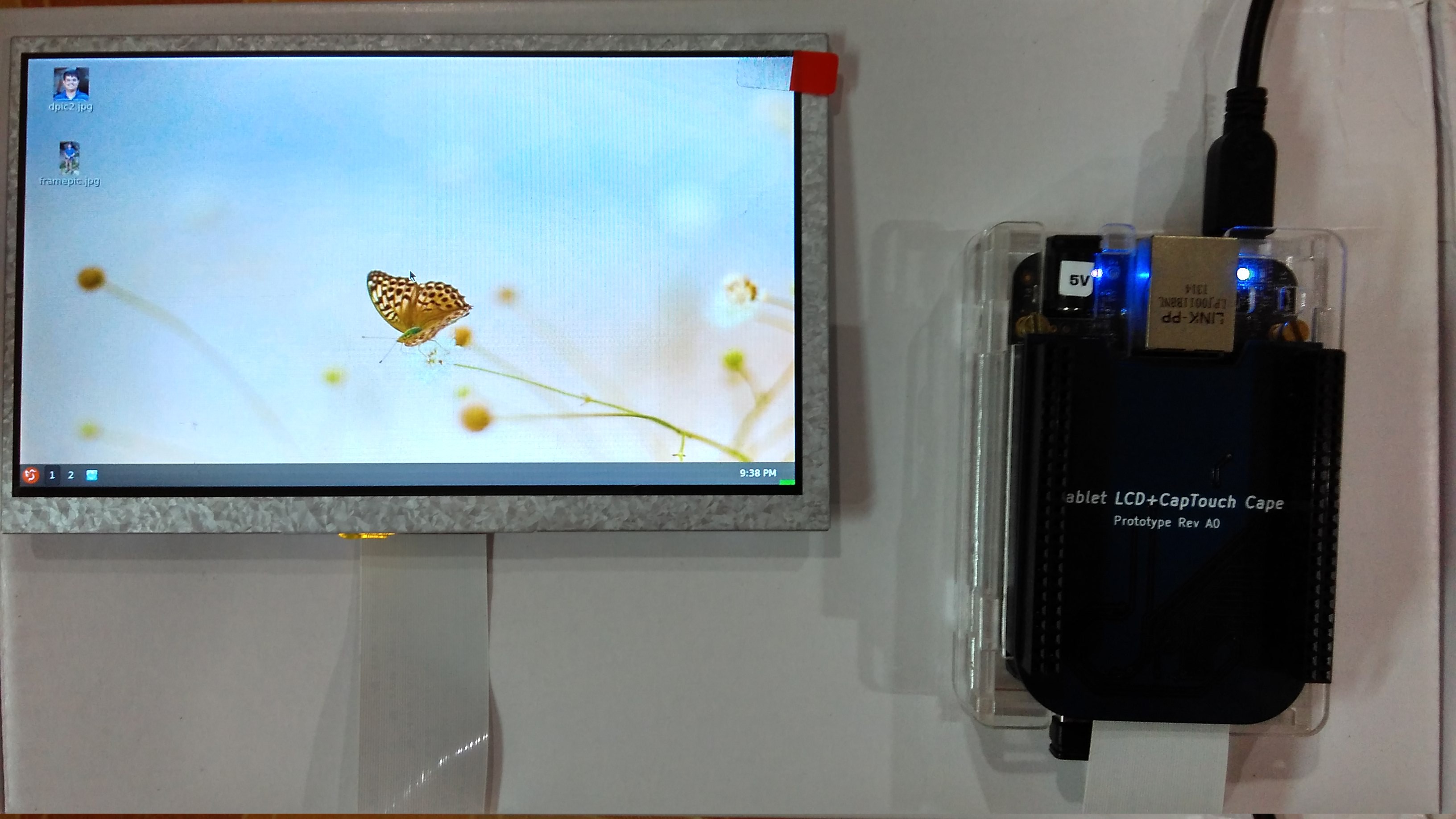
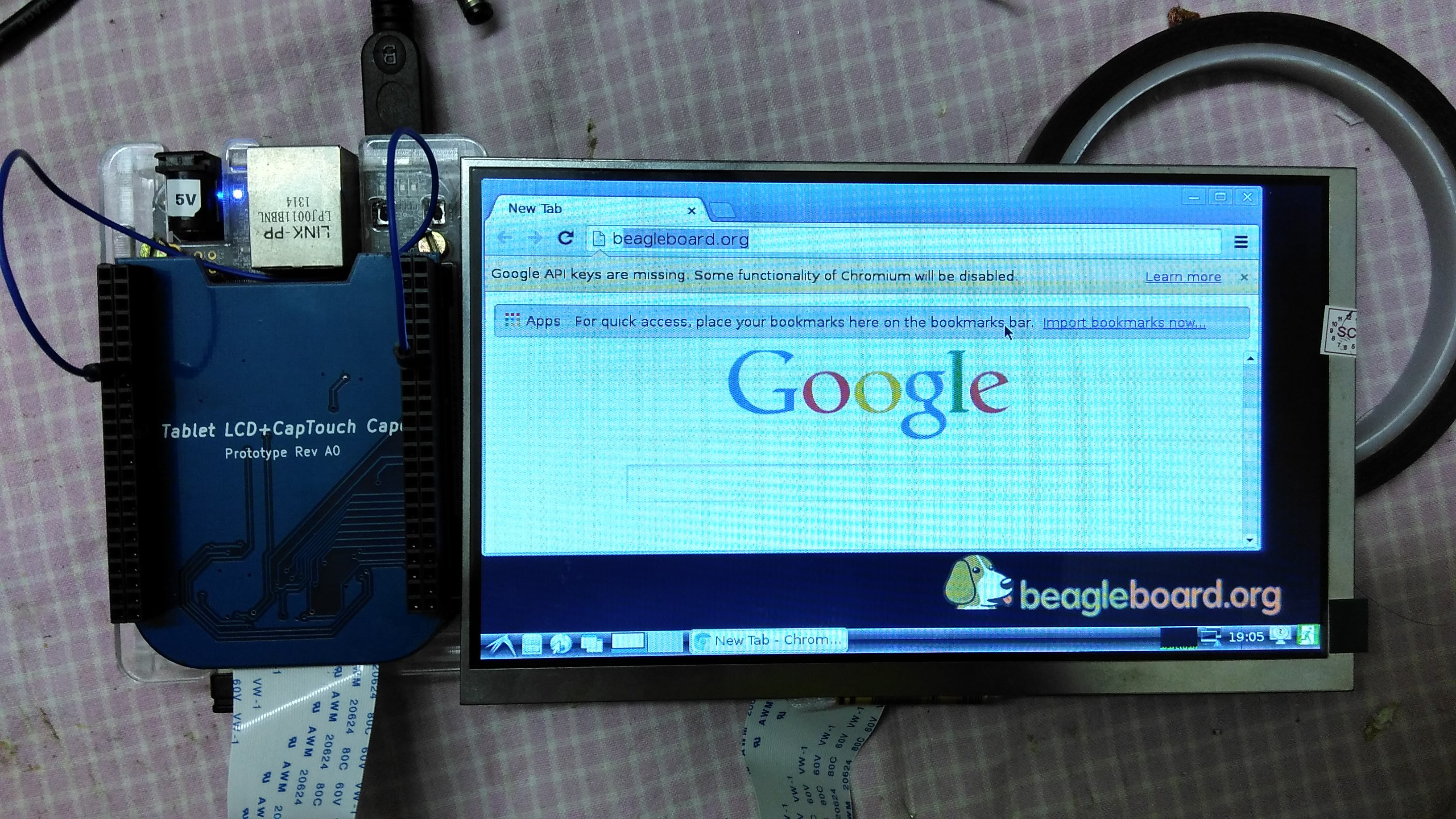
 Powered on, this is how everything looks like now, it was really worth the time to carefully align the display and the touch panel:
 Video coming soon!
The LCD adapter board allows for a capacitive touch screen to be attached to the BeagleBone Black as well. The capacitive touch screen I use has a FT5306 touch controller, which supports upto 5-finger touch. It has a 6-pin FPC and the pin out is printed directly on the flex connector:
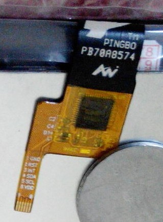
The touch panel is powered by 3.3V [VCC and GND] sends touch data via I2C [SCL and SDA]. The INT pin goes low as the screen is touched and this acts as an interrupt for the BeagleBone to sample touch data, and then there's the RESET pin.
If we look at the pin-out of the AT070TN90 LCD datasheet , we find that pins 45, 49 and 50 are NC (not connected) [Note that it also lists the 1,2,3,4 pins at NC but they are meant for the LCD LED Backlight]. So we have 3 spare pins. Could we squeeze the touchscreen data lines into this? Yes!
So VCC and GND connect to the DVDD and GND of the LCD panel, and then RESET is shared between the LCD panel and the touch panel. This leaves us with 3 pins - INT, SCL and SDA which can be squeezed into the 3 NC'd pins of the panel and carried to the cape in the same 50-pin FPC.
The touchscreen controller module is "edt_ft5x06" which is already present in the mainline Linux kernels. So we just need to write appropriate DTS for it, and it will work right away. Here's a snippet of the one used:
touch: edt-ft5x06@38 {
    status = "okay";
    compatible = "edt,edt-ft5x06", "edt,edt-ft5306";
    pinctrl-names = "default";
    pinctrl-0 = <&ctp_int_pins>;

    reg = <0x38>;
    interrupt-parent = <&gpio2>;
    interrupts = <14 0>;

    touchscreen-size-x = <1024>;
    touchscreen-size-y = <600>;
};
Notice that even though our display is a 800x480, the touchscreen which I bought must have been intended for a tablet of display of resolution 1024x600. When I put 800 and 480 in them, the touchscreen required additional calibration. When size X and size Y are set to 1024 and 600, the touchscreen works perfectly without any additional calibration.Uploading a video shortly.
I had bought two displays to test with this cape - one was a "KR070*" and the other was an original Innolux AT070TN90.
The AT070TN90 required some tweaking with the LCD timings (H/V front porch, back porch) but after doing that everything was good and here are a few shots.
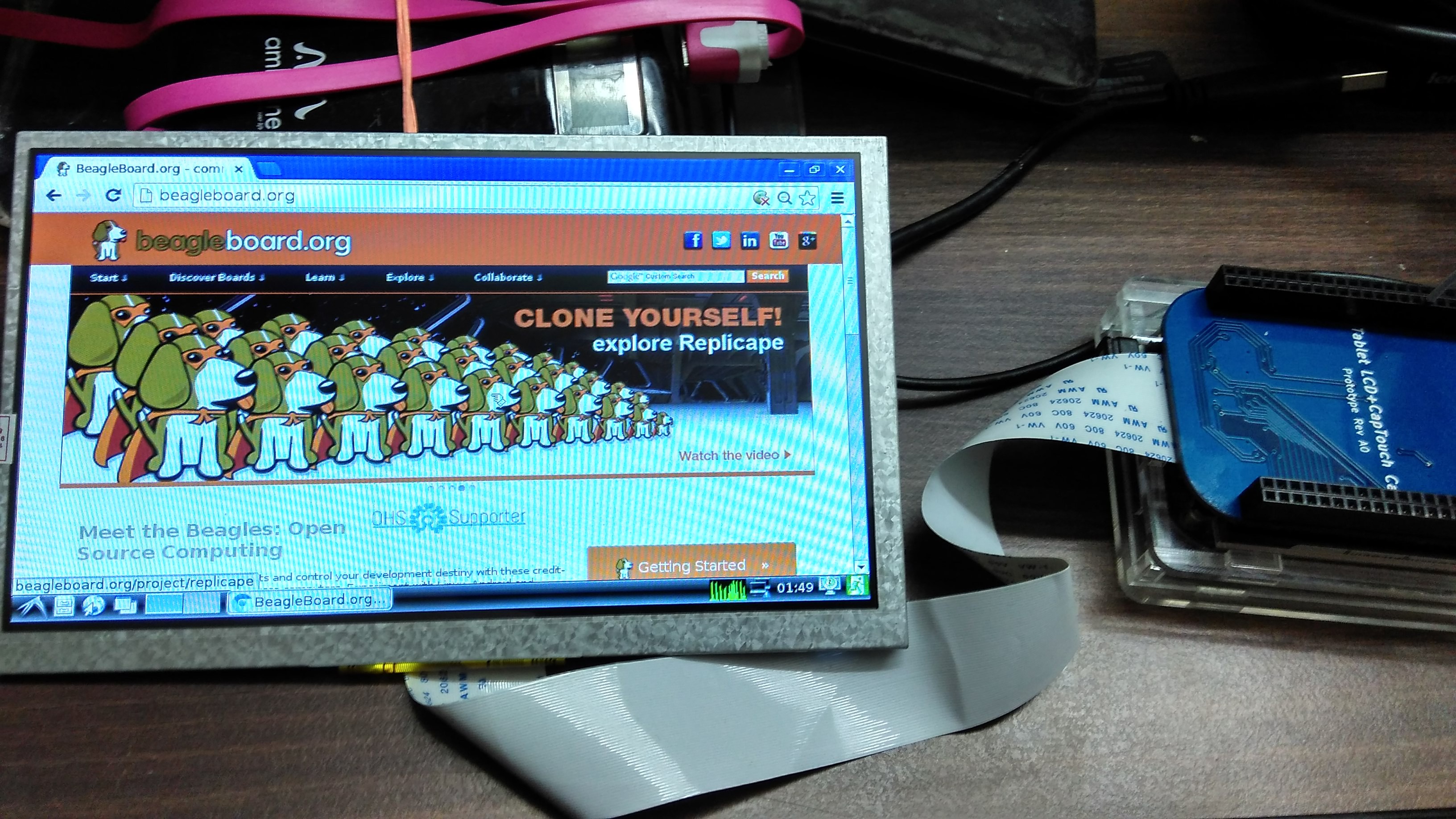
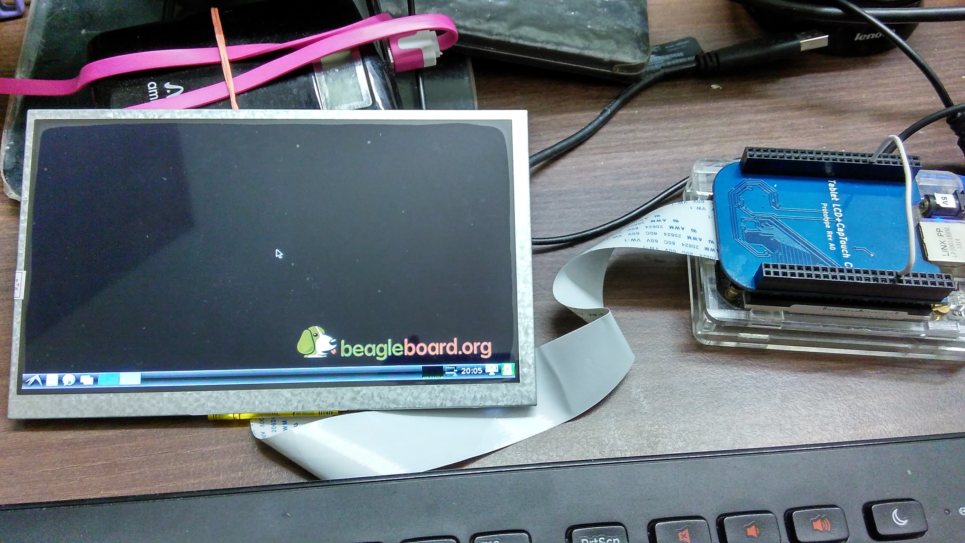
As you can see the blacks on the Innolux original display are richer than the Chinese clone. Also the backlight is more even and viewing angles are a little better. I'll be using this display for now, and when I get back to the market I'll experiment with more LCD types.
The issues I faced this time were the incompatibility of the device tree compiler (dtc) with the kernel version I have on my BeagleBone which was causing the modified DT overlay to give errors and do not load. But once that was fixed rest went on smoothly.
Now I have to find a suitable driver for my FT5306 capacitive touch panel, I would need to make DT entries for that. Let's see how it goes...
(DT : Device Tree)
After a week of after-work evening debugging sessions, adding bypass capacitors at "strategic locations" which had zero impact on the display stability and looking at the signals under a scope, I realized that the issue actually is the "ringing" during the switching of the inductor, so bypass caps addition wasn't really helping us here at all.
The solution was to add a "snubber" consisting of an RC network at the FET switch [SW] terminal of the boost converter to dampen the transients. This TI appnote proved to be helpful: minimizing ringing in boost converters. I took the values straight off the appnote [10R and 330pF] and after soldering them and powering up :
This is just the first step. Next up is to get it working with the capacitive touchscreen, and then put it all in a nice lasercut / 3D printed housing for this thing.
First try, and we've got a shaky display. Very shaky. I can make out the Beagle dog logo, see screens changing but the display isn't stable at all.
Soldering problem? Ran the soldering iron across the FPC connector to make sure all joints are tight and good. Did a continuity check, all connections look good, no bridges when viewed under a magnifier.
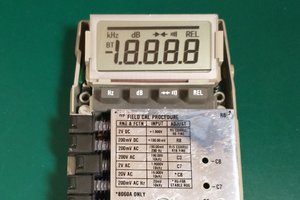
Continuity loss? Used a multimeter to check connections to the FPC. All looks good, nothing strange. Somewhere in between this testing the LED backlight wasn't lighting up when I connected the LCD. Whoops! I burn 4 LED drivers in the process (but they seem to have open LED "protection"?). Add a 16V Zener across the LED lines to prevent re-occurrence. The LEDs are in a 3-series (and currently unknown parallel lines) configuration and draw 9.5V.
Maybe some signal integrity issues? It's Scope time.
On testing with a multimeter, the LCD (with backlight) draws ~400mA from the power rail.
Okay, now that we know the issue, we should need to just add some bypass caps to fix it? Sprinkle a few 10uF 0805 ceramic caps, one before the LED driver and the other across the LED driver output still the display appears to be as unstable as it was before.
At this point I asked in the HaD channel, and with feedback that maybe the onboard 3.3V of the BBB is not supplying enough current to power everything, try to power the entire cape with a 1117-3.3 fed from the 5V of the BBB. An unstable display, still.
I look at existing cape reference designs (CircuitCo BB-VIEW7 and 4DSystems 70T) and find that they power their LED drivers off the 5V rail, and not the 3V3 VDD rail. Maybe they knew something about ripple from LED drivers affecting the LCD supply?
(To be continued)
Shot a time lapse video of the assembly work, which can be found here:
Now, onto the tests.
This was the first time I used Elecrow's services, and they delivered really nicely. The silkscreen could have been a little better but it's hard to complain at such price points also there is no sneaky serial and batch numbers anywhere unlike other manufacturers .
This board's gonna take some time to assemble, and I'll probably space the components out a little bit more when laying out PCBs the next time.
Design ready to be sent to fabrication.
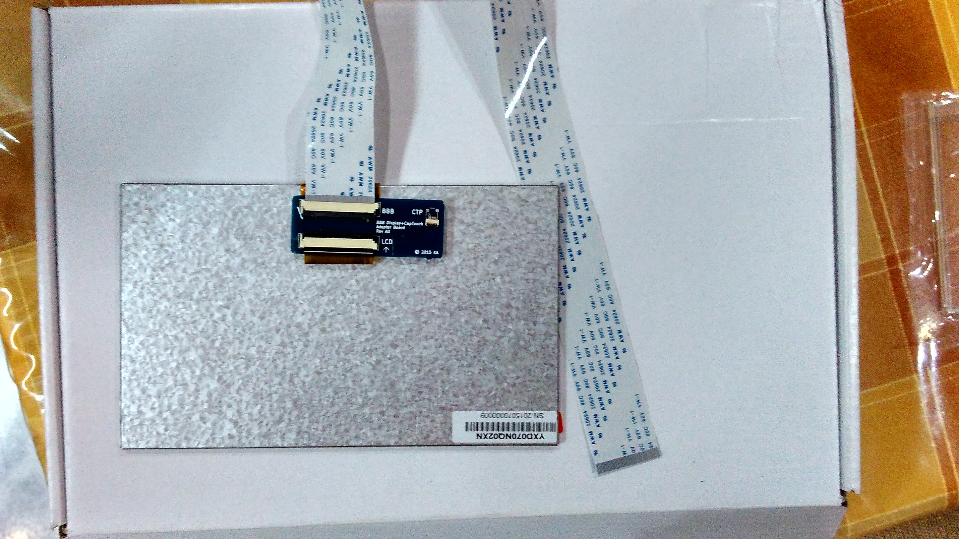
Note that there's a separate PCB to be attached to the back of the LCD panel. It combines both the capacitive panel and LCD signals into one 50 pin FPC.
KiCAD 3D Render of the finished design.
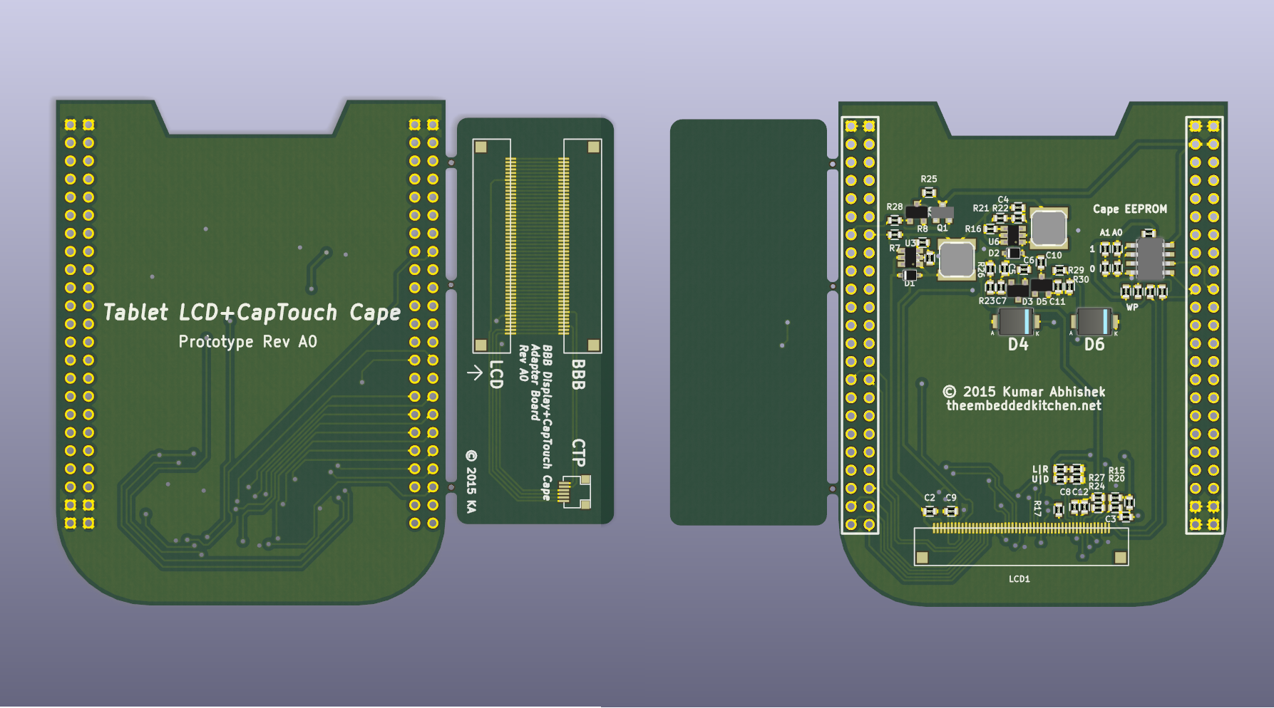
Just finished routing the PCB:

At the bottom there's the 50 pin FPC connector for the panel. The placement for the LCD data bus was a bit weird, and I had to use a lot of vias there.


Can you share any of the code you used to drive the display?
There were some LVDS capes at one time, but at present I can't find any LVDS or TTL capes... this should be for sale! Got any more circuit boards left?
Great! please where can I get the cape? I have some LCDs and I have made some hole on them to fix some Hall sensors behind, but the PCB driver (80009) ,I have,don't worked seems to be for composite videos. Do not worked with Bone's HDMI
please send me the dts file, I have a 4.3' display with touch panel (edt_ft5x06)
 ogdento
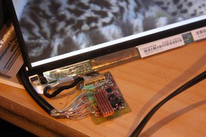
 Jared Sanson
 coon
coon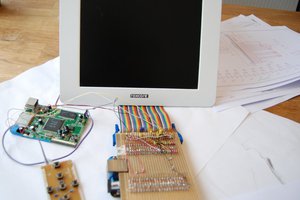
I have a ips display which supports hdmi with audio.While the BeagleBone Black works perfectly with hdmi video display,but after trying several kinds of resolution and fixing,the audio just doesn't work.The display itself and UBOOT of BBB are mostly OK,so maybe is there some compatibility issues or some tips I missed?