 ric866
Once that was done there was still a very quiet output from the left channel. I started troubleshooting with no schematic, armed with a meter, I found no fault components (all the transistors were fine). Next step was to grab the tone generator (android apps are excellent for this). Shoved my old valve oscilloscope in circuit at various points and worked out where the signal was going on each channel, and where the left side was getting lost.
I feel I should mention 2 things at this point. One, the left and right amplifiers on this unit are pretty much mirrors of each other, this is the only thing that made troubleshooting possible. Two, there are scary voltages and currents available inside these things (this led to my undoing later), if you are unsure I wouldn't poke about with power amplifiers capable of this level of output (my oscilloscope occasionally touched down in the wrong place and took 140V DC, it's hardcore and survived).
At this point I was very pleased with the progress. Nearly there I thought. Just need to adjust the Bias to stop the overheating. A little research revealed around 20mV across the output resistors would give an acceptable current flow through the power transistors (enough to keep the junction open, but not get them too hot). After adjusting the Bias pots, and re-checking each time, I was struggling to get the voltage to an acceptable point.
On metering for the fifth or sixth time I slipped and one of my meter probes (which was just tinned wire for accuracy *see life lesson at the end) crossed between the input and output track of one of the transistors (between DC +-70V) unfortunately as soon as it made contact, it welded itself to the board (as per the scorch mark image) put the power amplifiers out of balance, and promptly (about 1/2 a second) caused one of the power output resistors to explode. Further putting the circuit out of balance.
It's hard to convey at this point, the scale of time and moment of panic that ensued. As I realised the device in my lap was infact on fire, I pulled the plug, unfortunately I was waaay too late to save it. After the smoke cleared and I had a cup of tea, I checked the damage. All the power transistors, several resistors, several of the control transistors and preamps on the left channel had been damaged. I was not best pleased.
*Life lesson, always use proper meter leads.
I had a decision to make at this point, repair or replace. In light of no schematic for the existing amplifier circuit, the potential of downstream damage to the rest of the preamps and resistors etc. I opted to replace the board. I am currently awaiting the arrival of a preamp, protection board, and a pair of amplifier boards (see the parts list). I intend to reuse the case (providing it fits), stabilized power supply and anything else I can salvage.
Watch this space...
 Justin Scott
 JT
JT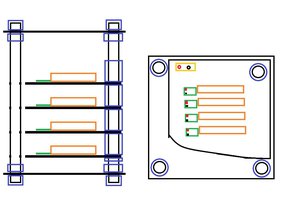
 cyplesma
 emuboy