 Justin R.
I purchased the digital dial indicator from Harbor Freight (Item # 93295) for $29. Now normally I don't have particularly high expectations for products from Harbor Freight, but I have to say that I'm actually quite impressed by the quality of this indicator. Even the box it came in was made from thicker cardboard and had a nice design. The indicator itself is made from more metal than plastic (only the front part of the case and buttons are plastic). The buttons have real microswitches behind them and have a nice solid feel.
But the real reason I got this indicator was in the hopes I would be able to extract/export the data and send it over to a computer. Now I knew other cheap chinese calipers tend to have a data port that other people have successfully been able read data out of, so I was hoping this would have a similar port even though it is not a caliper.
The first thing I noticed after buying it was there were two covers on the top of the indicator. One of them held the battery and the other one happened to have the magic data port I was looking for, Yay!
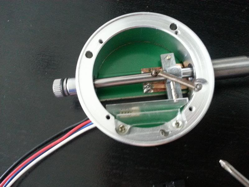
Unfortunately I didn't take any pictures before proceeding to tear it completely apart, but I have the next best thing, pictures of it going back together:
Exploded View:
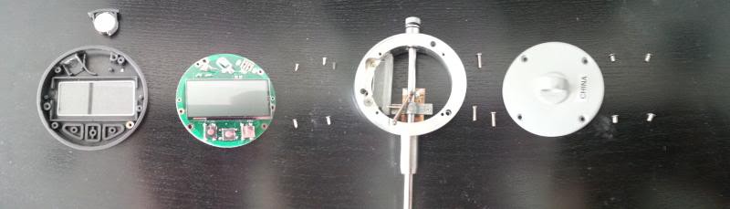
Exploded View (everything flipped over):

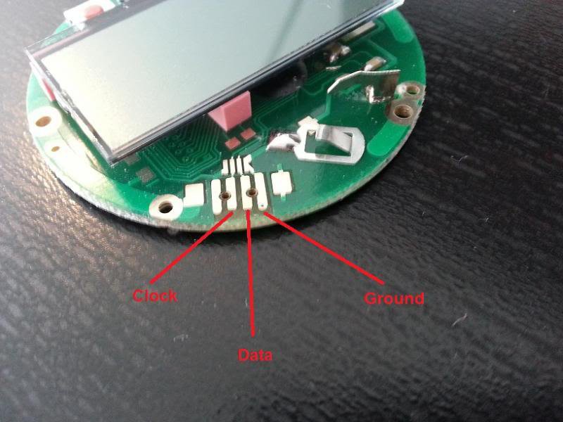
After some quick testing I found this was the pinout I wanted from the data port:
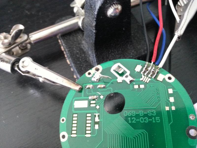
Soldering the wires on to the pads of the data port:
After getting everything put back together, I tried to test it out by connecting it to the logic analyzer part of my USB oscilloscope. I couldn't get any reading to show up and it turns out that the voltage levels of the clock and data line are just too low to be picked up by the logic analyzer (1.3 V = High). So I ended up having to use the 2-ch oscilloscope function to take a look at the data.
Here is the reference I used on how to interpret the data being output by the indicator: http://www.yuriystoys.com/2013/07/chinese-caliper-data-format.html
Data is output in six 4-bit nibbles. The first five sent represent the measurement in binary scaled by 2000 counts per inch (when in inch mode). The final nibble is a status word that indicates whether the measurement is positive or negative and also whether it is in inches or millimeters.
Proof of Concept Test:
Setting the indicator to an arbitrary distance, I tried to interpret the data to get a measurement that matched the display.


Keep in mind that the measurement value is sent LSB first, MSB last (so its basically backwards in the above image, at least for the way I'm used to seeing numbers). 111111100 converts to 508 decimal and after dividing by 2000 counts/inch, it gives us 0.254 which matches the display! So now we know how to make sense of what is coming out of the indicator's data port.
Next Step:
I need to figure out the best way of importing this data to the computer controlling the CNC router. Right now, I think it is to use a PIC chip to interface with the indicator and then send the data to the computer through serial UART (with a USB adapter on the computer side). I'll also have to come up with some circuitry to allow the PIC to read the 1.3 V levels output by the indicator (probably just a transistor with a pull-up, since it won't matter if the signal gets inverted).
Discussions
Become a Hackaday.io Member
Create an account to leave a comment. Already have an account? Log In.
I thought these indicators have only optic interface. Is this so? Or there are many variants in what you insert into the data slot of this indicator?
Are you sure? yes | no
've been working on a Raspberry Pi interface for this indicator to use in a Foucault tester for telescope mirrors. I'm using 2 logic level shifters from https://learn.sparkfun.com/tutorials/bi-directional-logic-level-converter-hookup-guide,
just a transistor and 2 resistors each.
I etched a circuit board with pins to match the jack on the indicator and cut a couple pieces of plexiglas, trying to make a plug to fit the jack, but didn't get it tight enough, so soldered wires to a 4 pin telephone jack, and from telephone plug to my circuit board.
Using my Scope, I can see the clock and data are level shifted, so plugged it into a couple GPIO pins on the Pi and wrote a python program to try reading it, but get garbage. I guess the python interpreter is too slow.
I guess I'll need to use C/C++ or arm assembler to keep up with the 150 micro second clock speed.
I took some pictures of the circuit board, etc., if anybody is interested.
Now how do I post this?
Are you sure? yes | no
Are you sure? yes | no