 Alex
Alex1. General
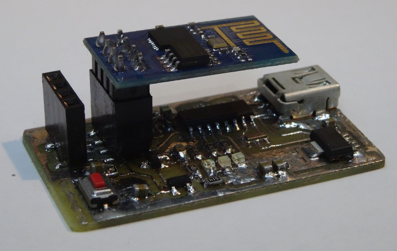
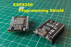
For experimenting with the ESP8266 I developed this little PCB. Experimenting with the previous setup on a breadboard was no pleassure. The main benefit of this PCB is a much better acces to the program-mode and the reset over one switch.
2. Circuit
The circuit is nothing special: The serial interface of the ESP-01 is connected over the CH304G bridge IC to the USB Connector. The USB is also used for Power. A 1117-3.3 voltage regultaor supplies the module an the CH304G with 3.3V. To enter the programm-Mode GPIO0 has to be pulled to ground. On the web I found som circuit (link) to reach this.
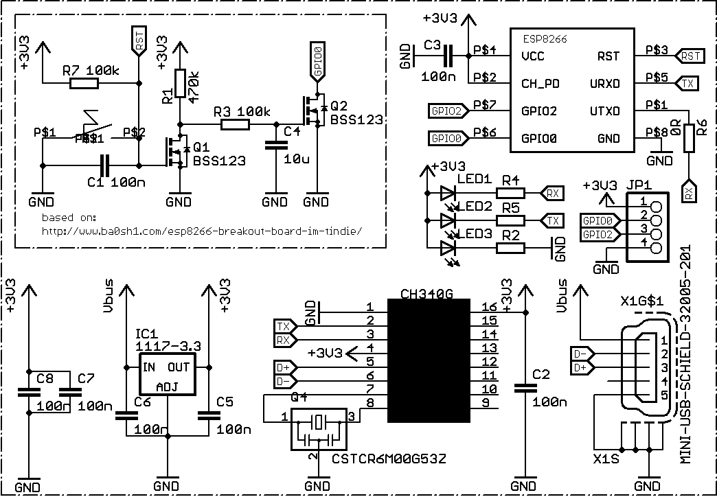
Instead of BSS123, like in the schematic, I used BSS138. They are pin compatible. BSS123 should laso work. R4, R5 and R2 can vary. I used 2K, so the leds are quite dark but good visible. R6 is just used as bridge over another trace.
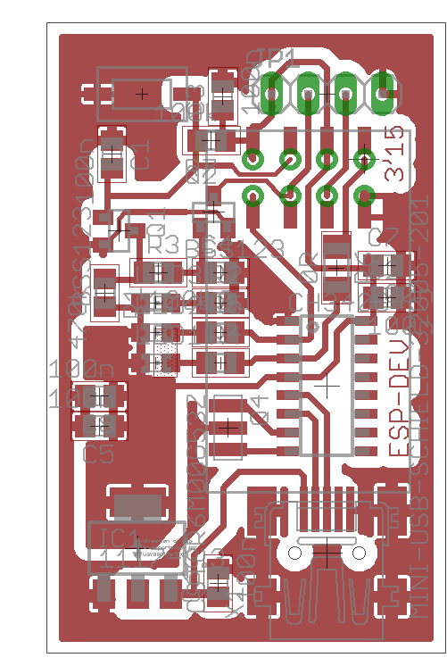
3. PCB
Based on the Circuit I deleoped this PCB. It is all SMD and single sided. This made it easy for me to etch it directly at home.
4. Conclusion
This board is a very usefull toll to play with the ESP-01 module. If you need more than the two GPIOs of the ESP-01 some of the other board with the ESP8266 should be worth to look at.
5. Future Development
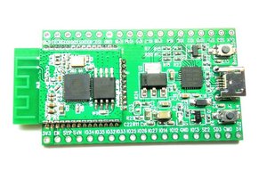
For this ESP-01 Board there will be no future development. Or at least this is my stand today. Other modules with the ESP8266 Chip have much more features (the ESP-01s were just laying arround here for some time). In future I will switch over to one of these other newer modules (some are allready on the way to me). There is a goog chance, that there will be a breaktoutborad similar to this for another module in future. Ideas which i could implement in future are:
- separate Power-In Jack and/or Header
- switching voltage regulator, the linear one gets quite warm
- on board lipo charger to power it off-grid
For the follow up project see #ESP8266 (ESP-07/12) Dev Board
If you find any grammar or spelling mistakes please consider, that English is not my native language.


 ElectroBoy
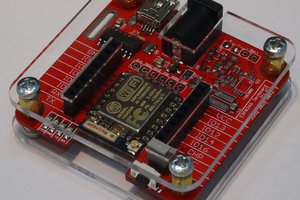
 Abraham
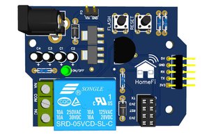
Care to share on OSHPark?
Very cool design!