Close
0%
0%

AM2XBee4RC

Repurpose your old AM RC equipment using Xbee and Arduino.

Similar projects worth following
I love RC stuff and I can remember the days of AM radios with their frequent radio interference problems that would send my high speed car directly into the curb and send me back to the hobby store for more parts. Fast forward 20 years and a now with a hand full of easily obtained parts, a broken transmitter and some wire, you can turn your old AM radio into a programmable multi-function multi-channel 2.4GHz RC controller. So RCycling? I think so.

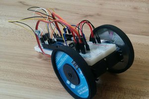
I came across a broken pistol-style AM controller awhile ago and figured it would make a great platform for a hacked together programmable remote. This project uses simple interface connections to the Arduino that allow for the sensing of control positions, illumination of indicator LEDs, battery sensing and the display of telemetry. The ATMEGA328, which makes up the heart of the Arduino, has 6 ADC's (used for control position and battery sensing) and 12 GPIO (used for the LCD control, encoder sensing, serial communication with the XBee and indicator illumination) making it a great platform for creating a new remote.

When you get started on a project like this, the first thing you want to take into consideration is space. While the Arduino Uno form factor is great for prototyping, it is terrible for embedded applications. So, for this project I decided to use my "Breadboardable" Arduino clone since it is quite a bit smaller than the standard Arduino and happened to be sitting in the bottom of my project box. (You could certainly use something like my SMDuino or a Pro Mini). For the receiver, I opted for an Arduino Fio as it is directly compatible with XBee's 3.3V requirement and can control servo's without any level shifting. Oh and yes, those wheels are 3D printed.

  • 1 × Sacrificial RC controller
  • 1 × Small form factor Arduino I am using my "breadboardable" Arduino clone. Link in build instructions
  • 1 × Arduino Fio For the heart of the receiver.
  • 1 × LCD HD44780 compatible for simplicity
  • 1 × Encoder For menu driving

View all 13 components

  • 1
    Step 1

    Amass your materials and get a nice space to spread out and work. Start by opening up your controller and begin the preliminary layout of the components. Remember that weight distribution is important, especially with a pistol style controller. you want to make sure that the heavy components, like the battery, are positioned in a way that makes holding the remote comfortable.

  • 2
    Step 2

    Remove the controller's control board. It should be held in place with a couple of screws. Inspect the board and locate the section dedicated to the AM radio. This is usually near or around the crystal and consists of a series of coils, caps and such, as well as an IC. Use a sharpie to draw around the circuitry and either desolder it or cut it out all together. TRY TO PRESERVE AS MANY MOUNTING POINTS AS POSSIBLE. This will be useful later if you choose to use any of the original pots, LEDs or switches. See what I did in the pics for reference.

  • 3
    Step 3

    Desolder all of the wires from the three pins on each potentiometer and identify the polarity of the LEDs you would like to use. I just went ahead and soldered 330Ohm resistors to the back of mine rather than try and repurpose the old SMDs.

View all 7 instructions

Enjoy this project?

Share

Discussions

Similar Projects

Does this project spark your interest?

Become a member to follow this project and never miss any updates