 Mike Rigsby
Here's the contest entry video.
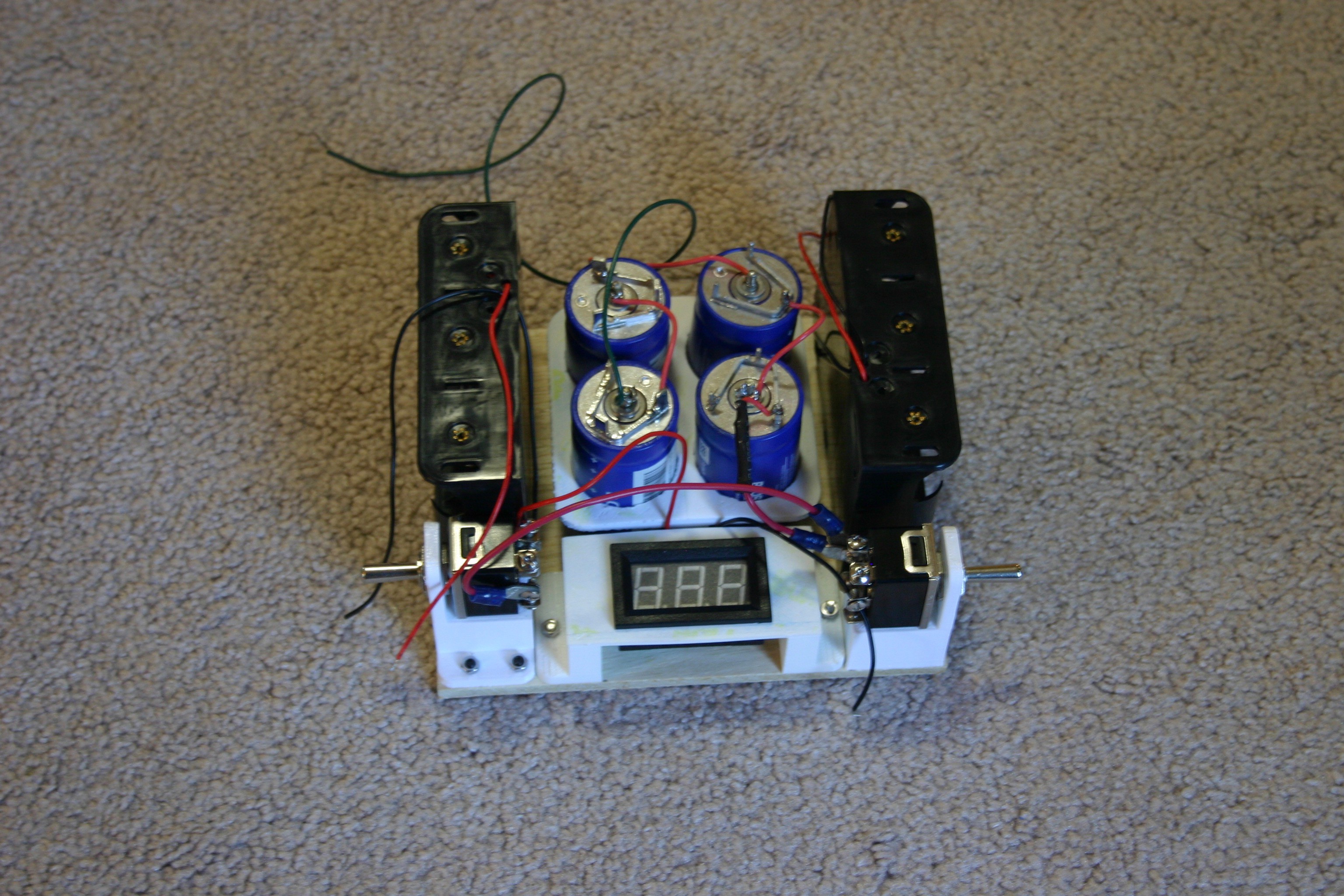
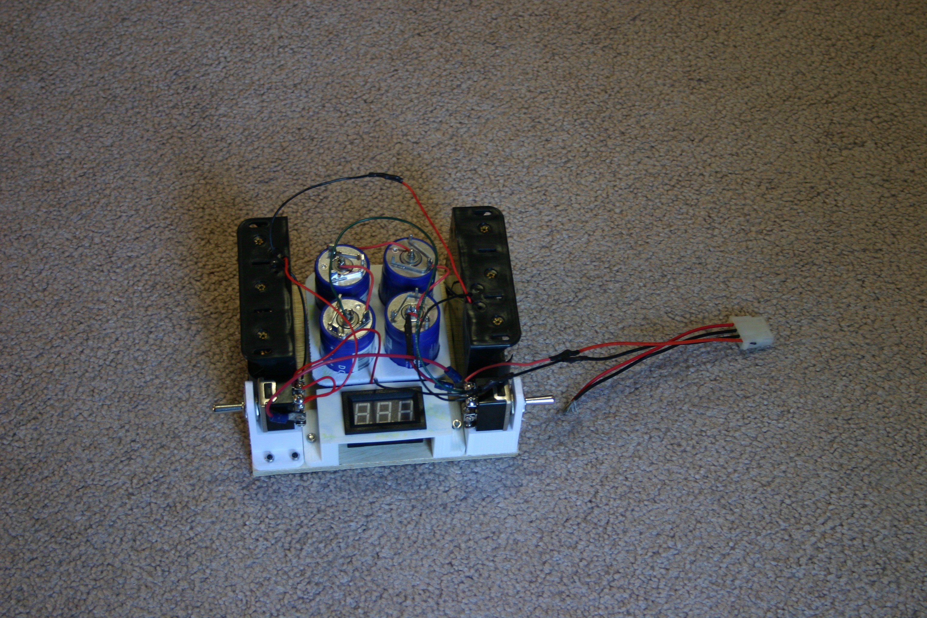
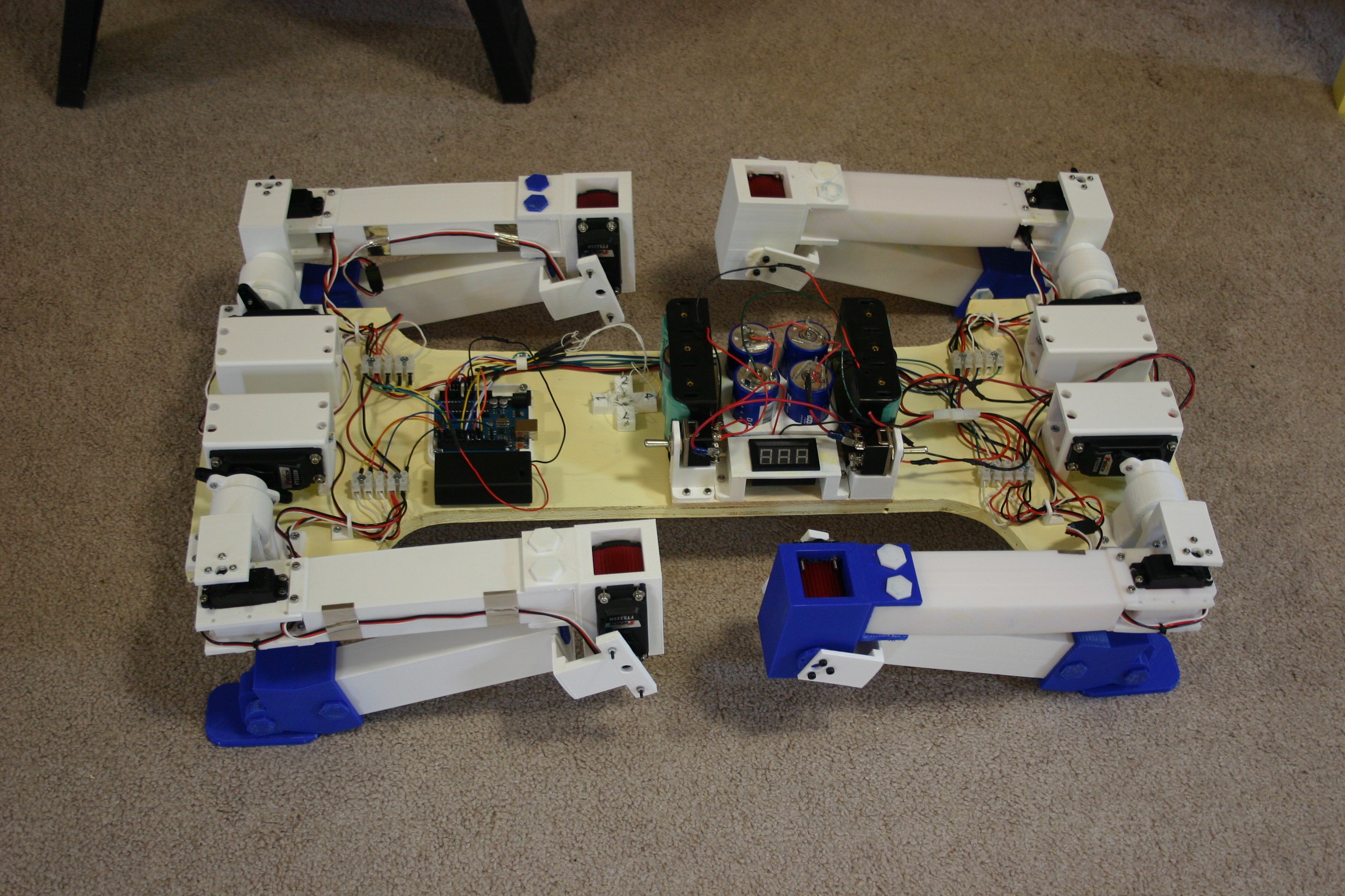
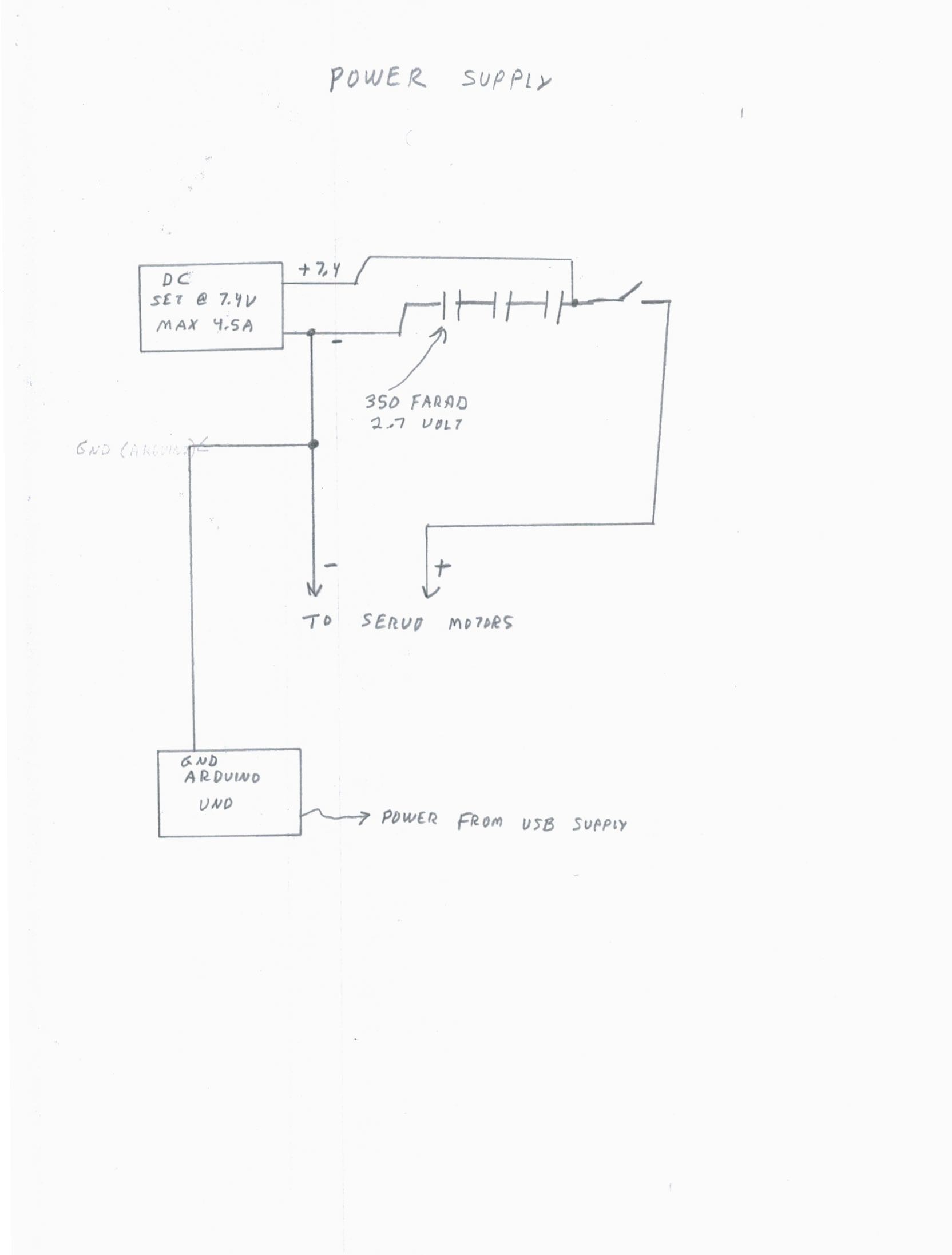
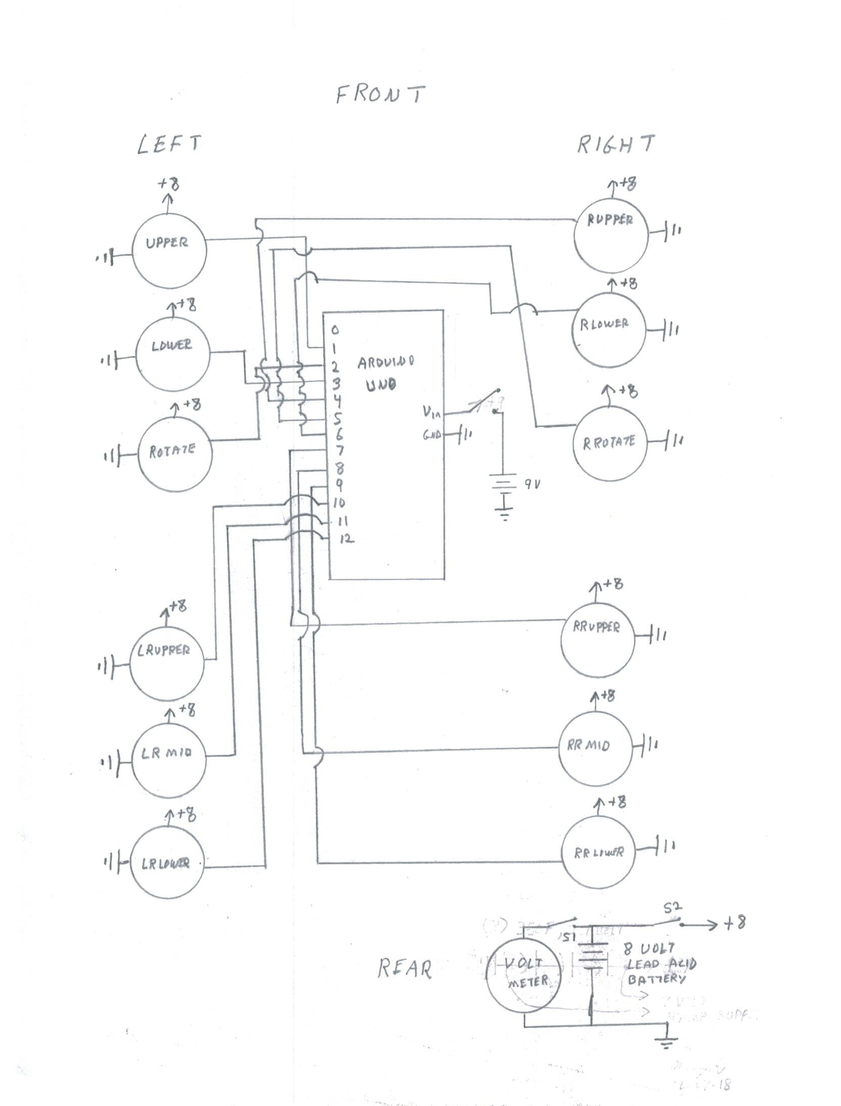
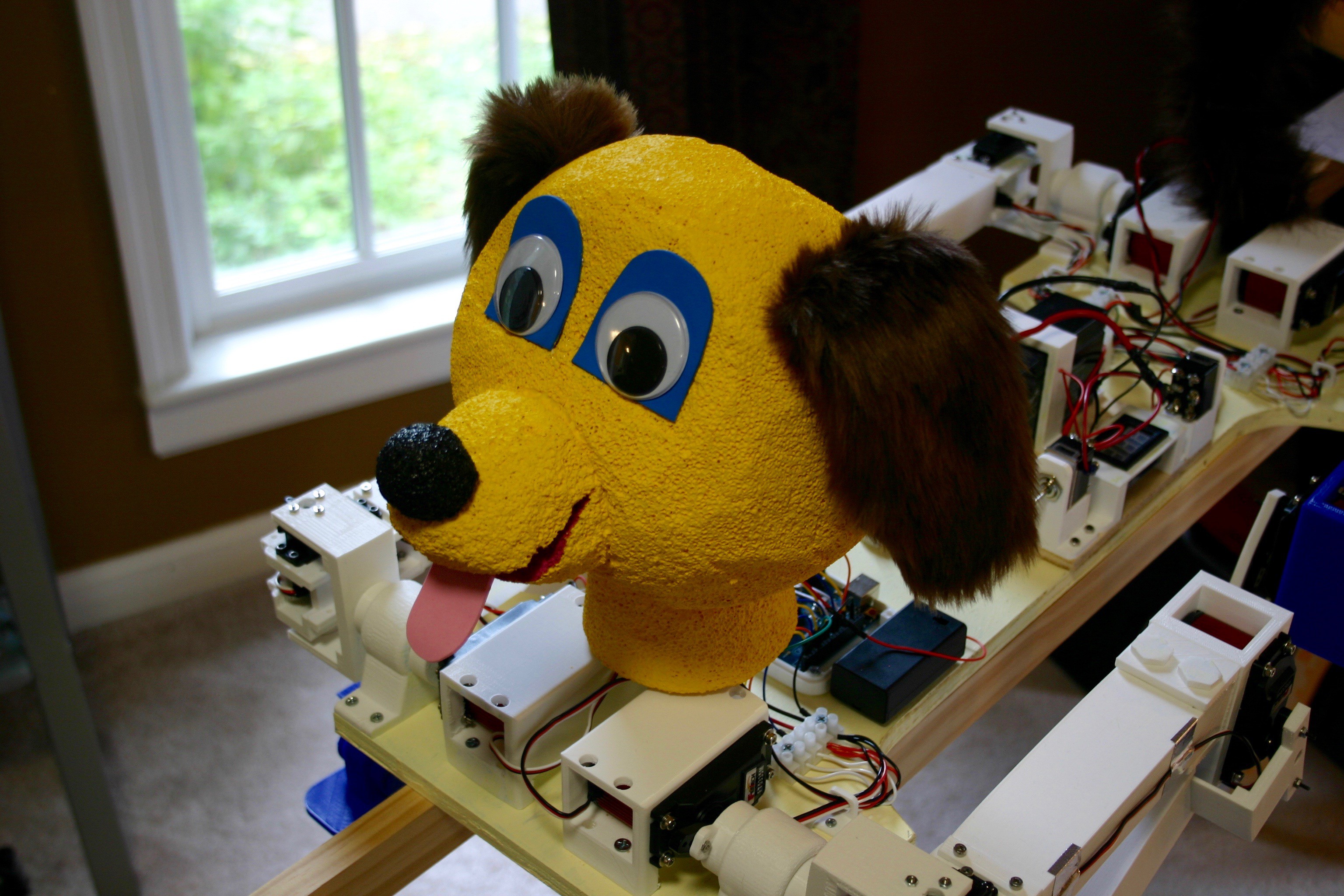
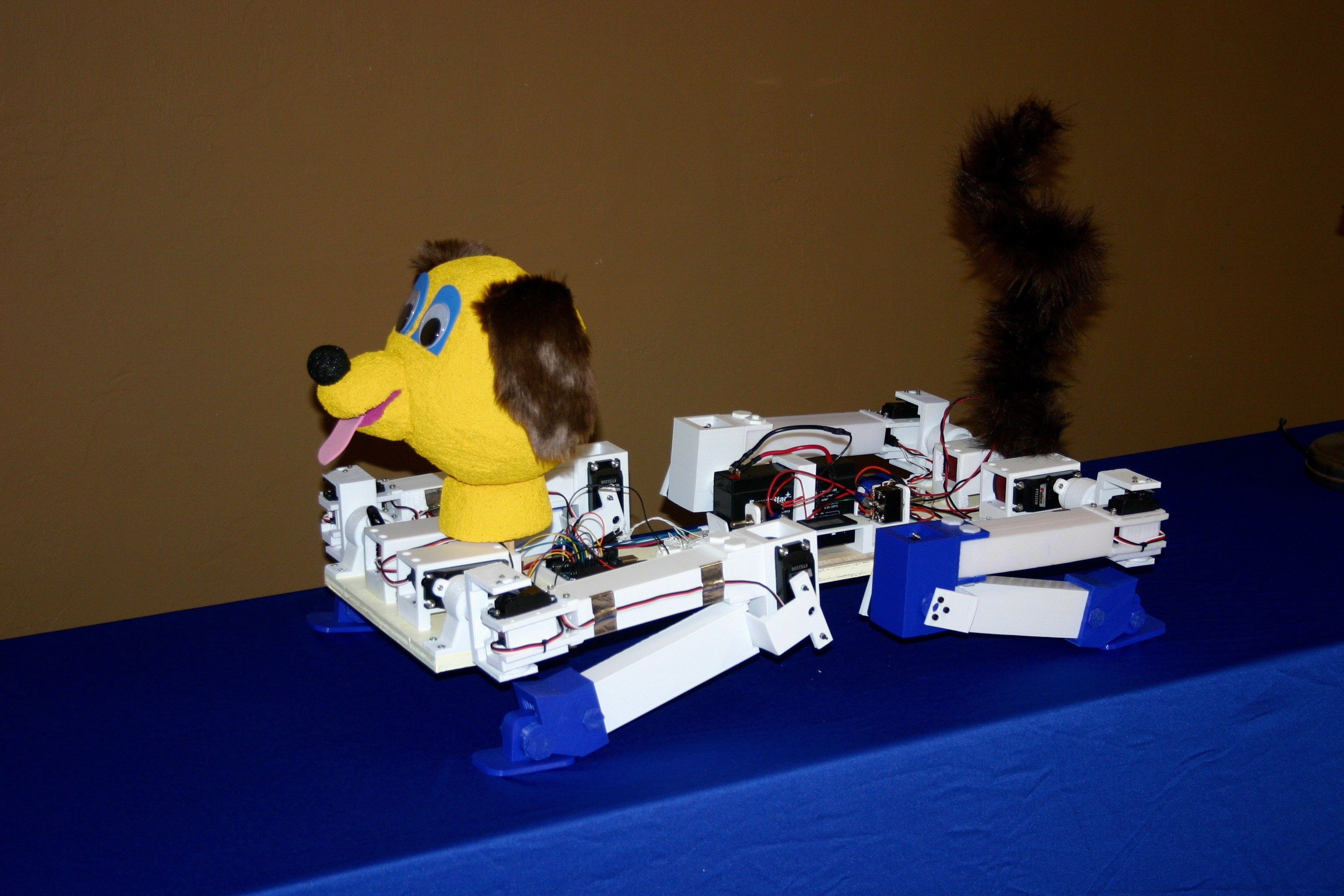
June 27--using an onboard power supply and Arduino, the dog can stand untethered.
The Plan
Increase torque of legs
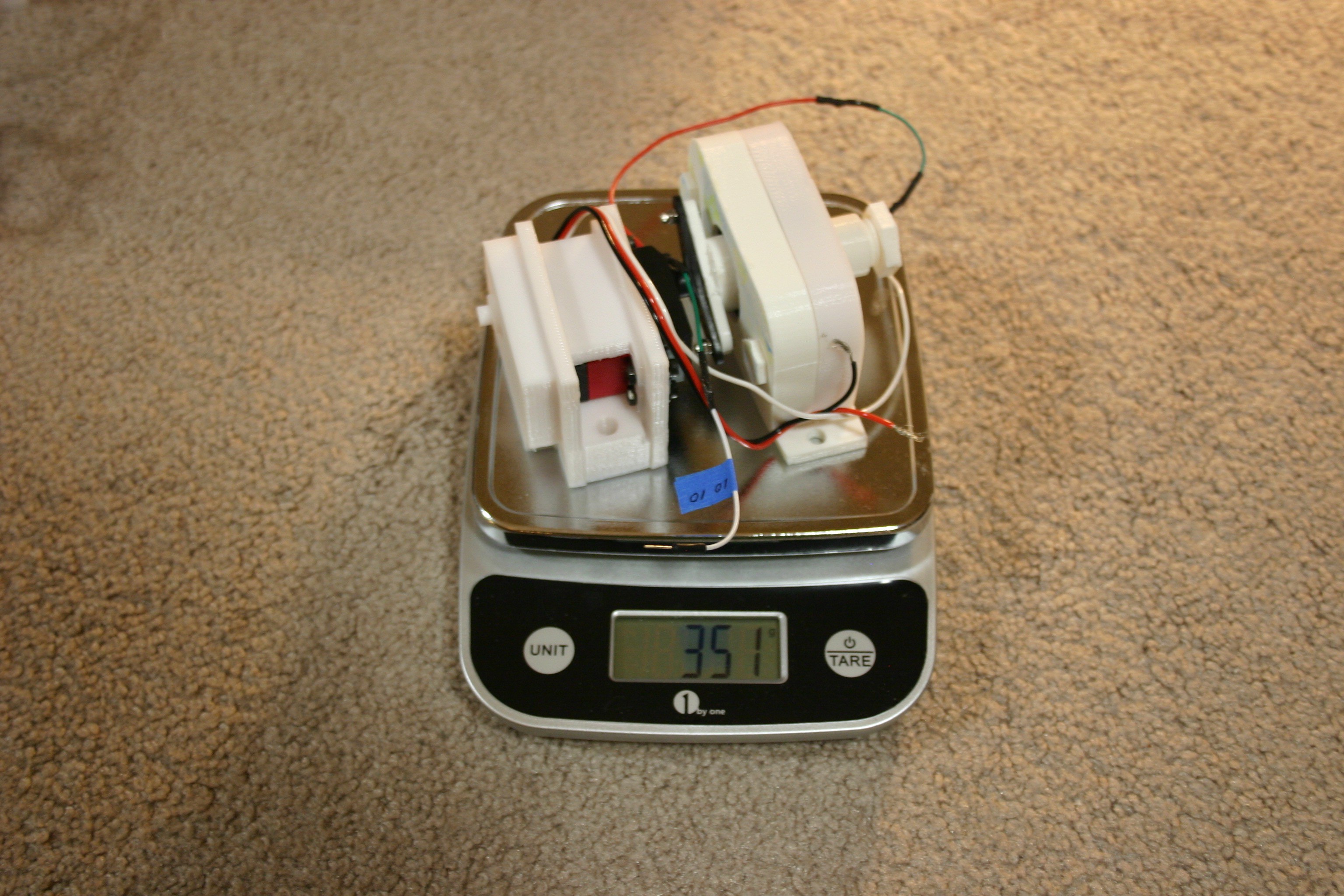
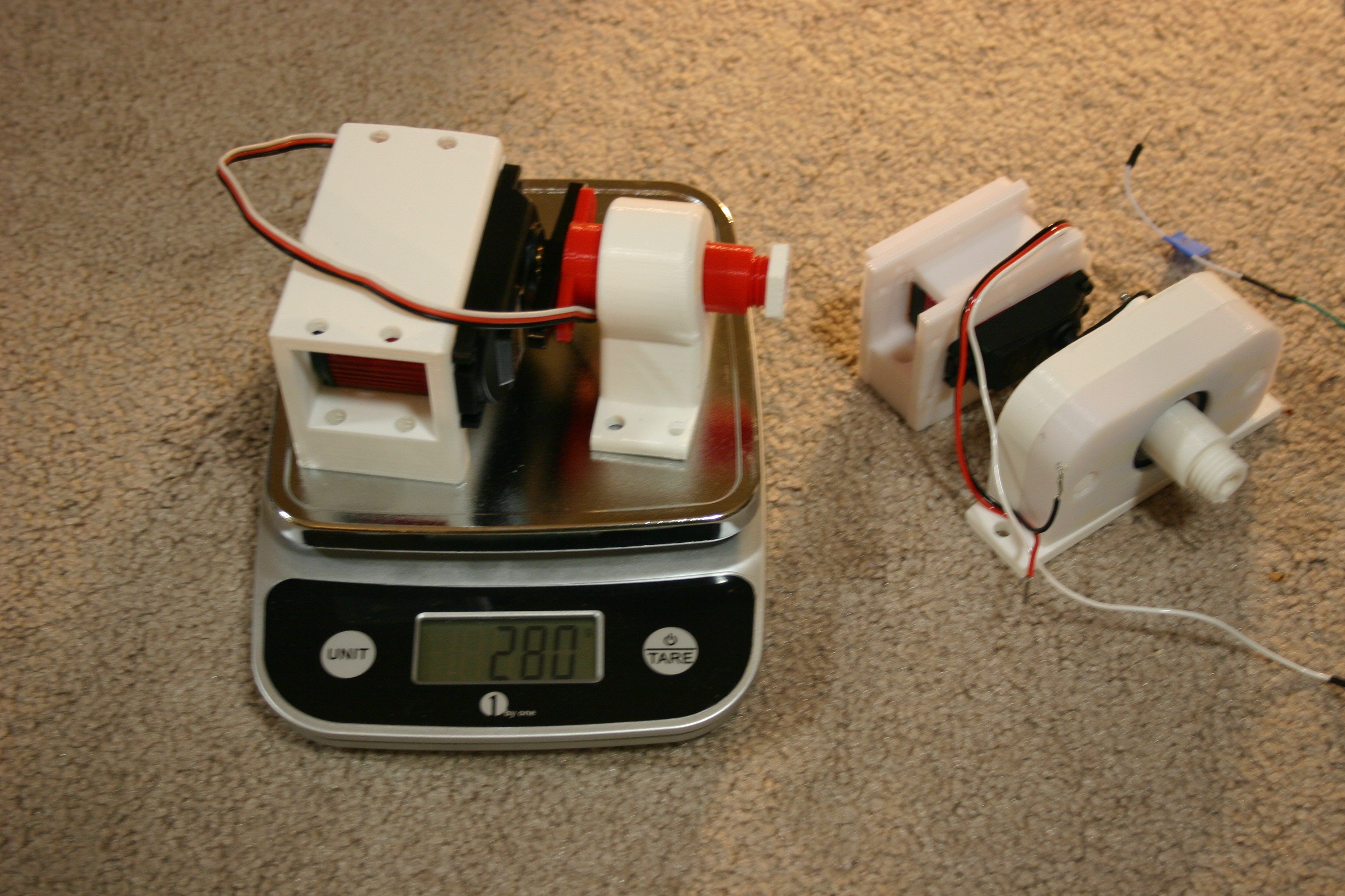
Decrease weight of legs
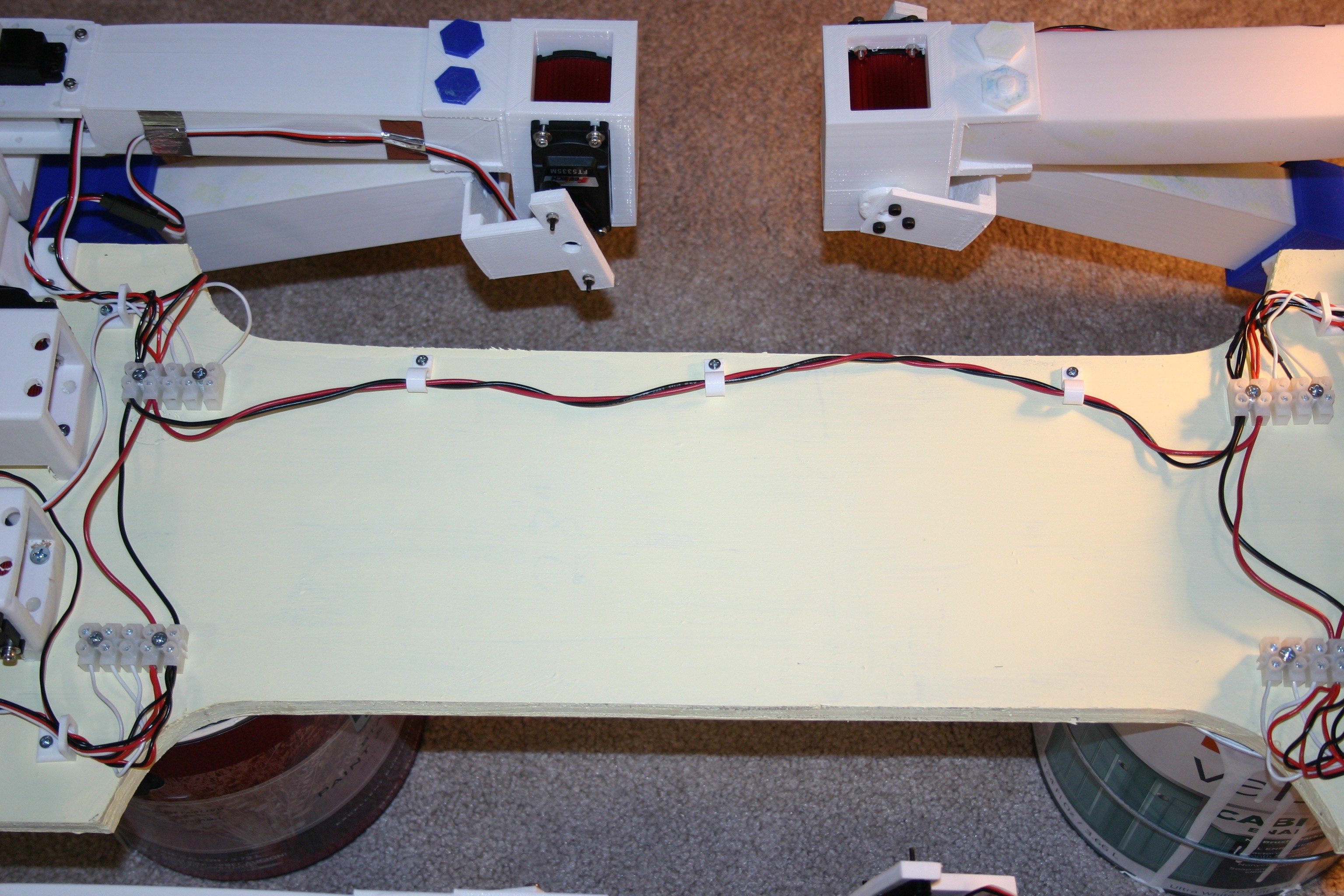
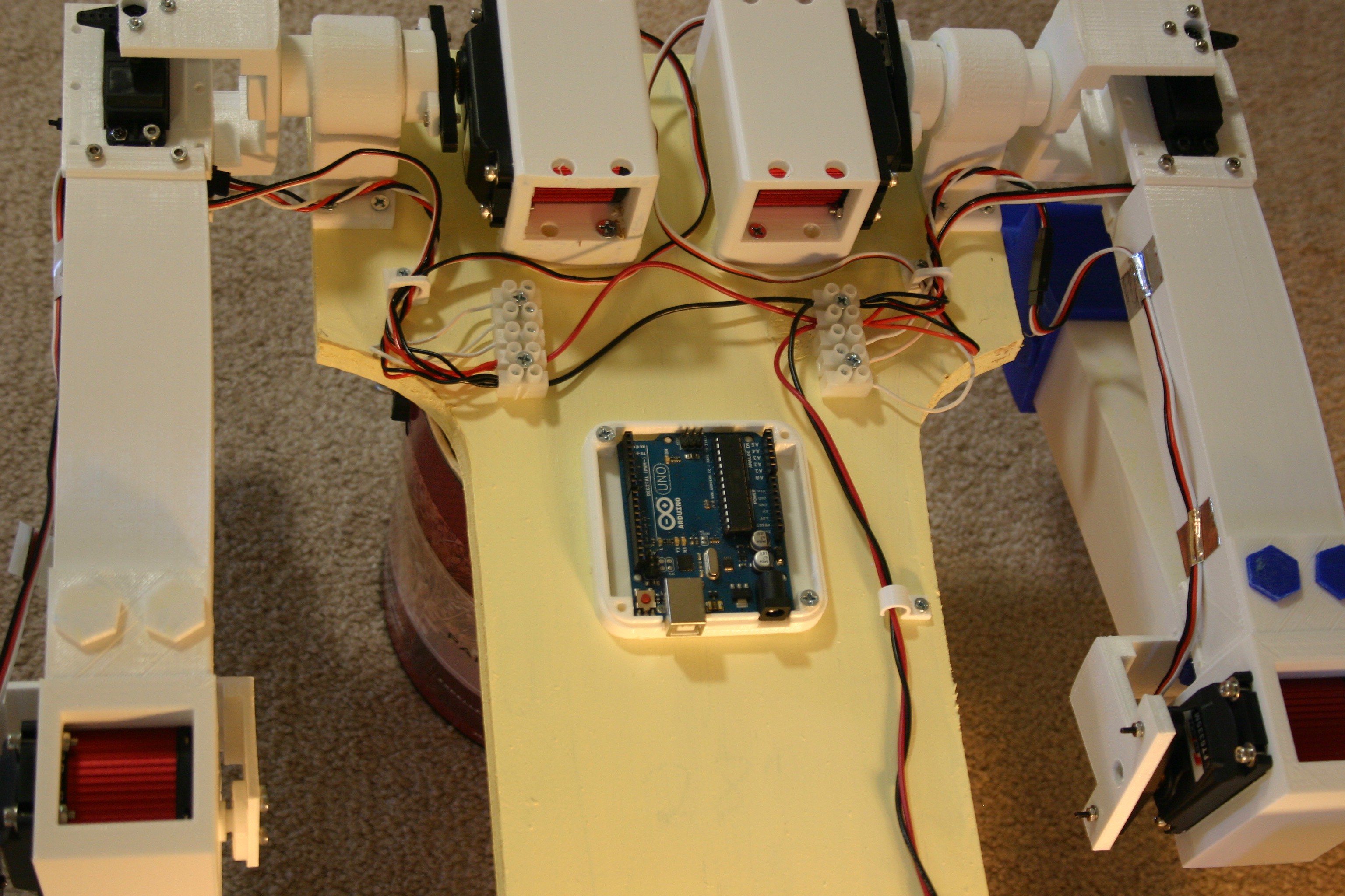
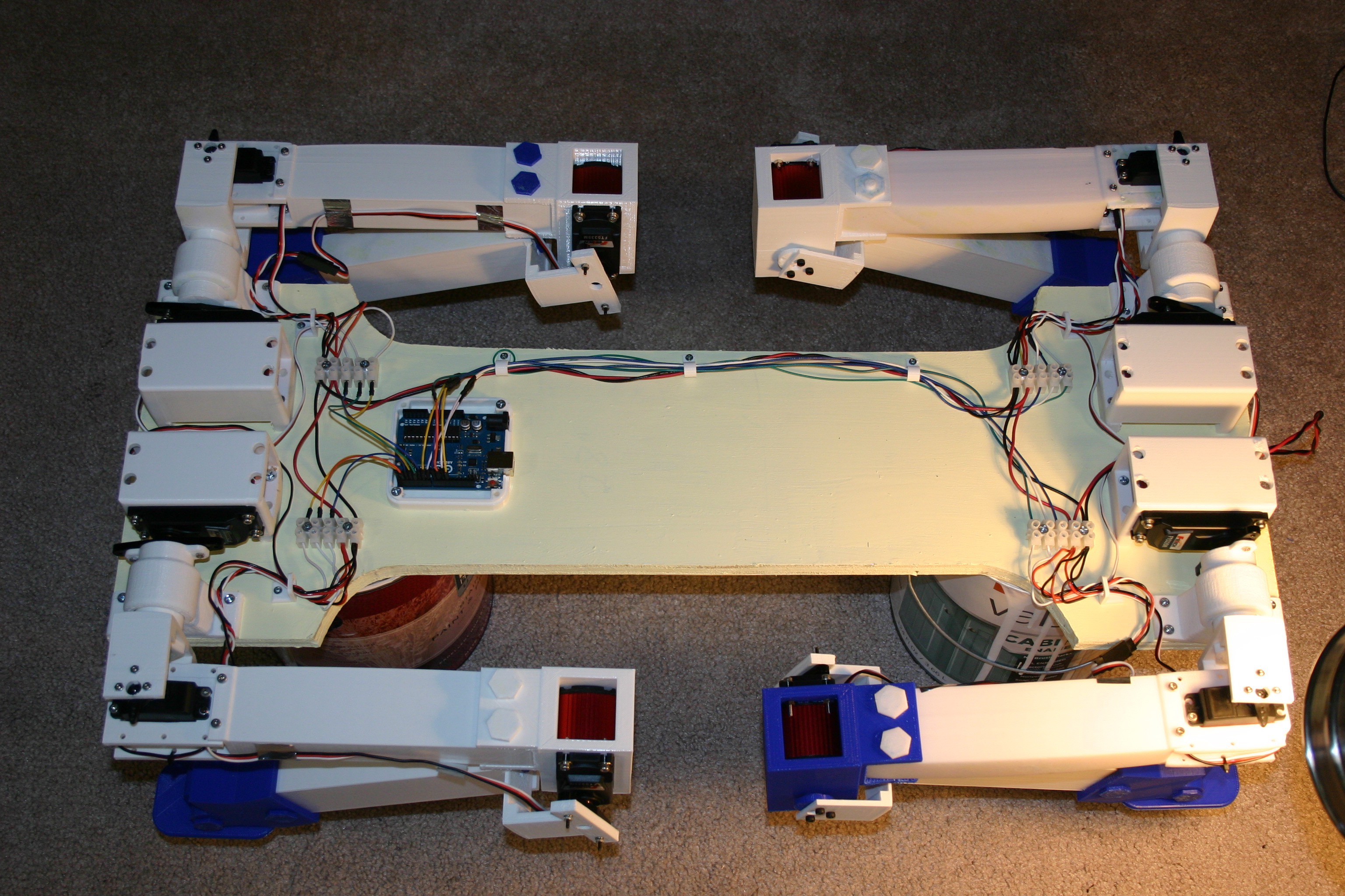
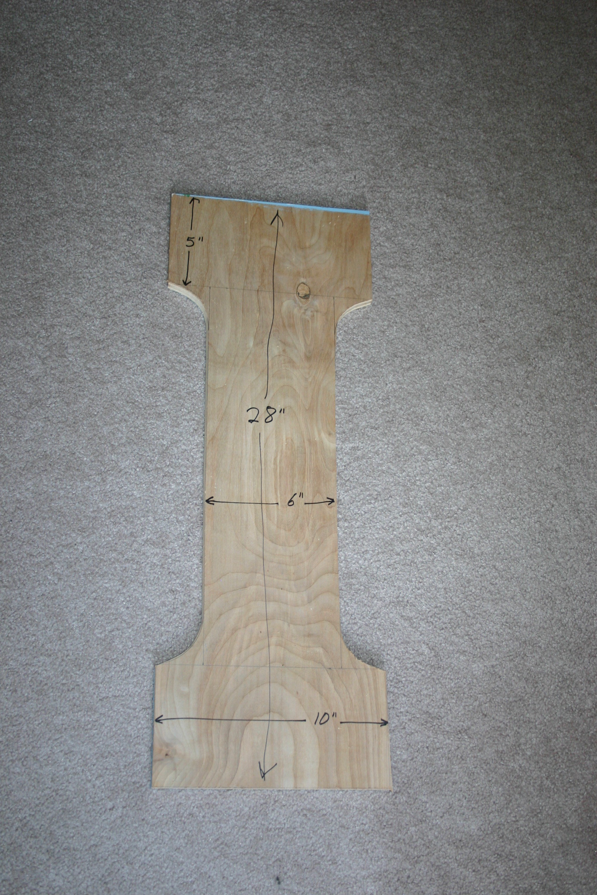
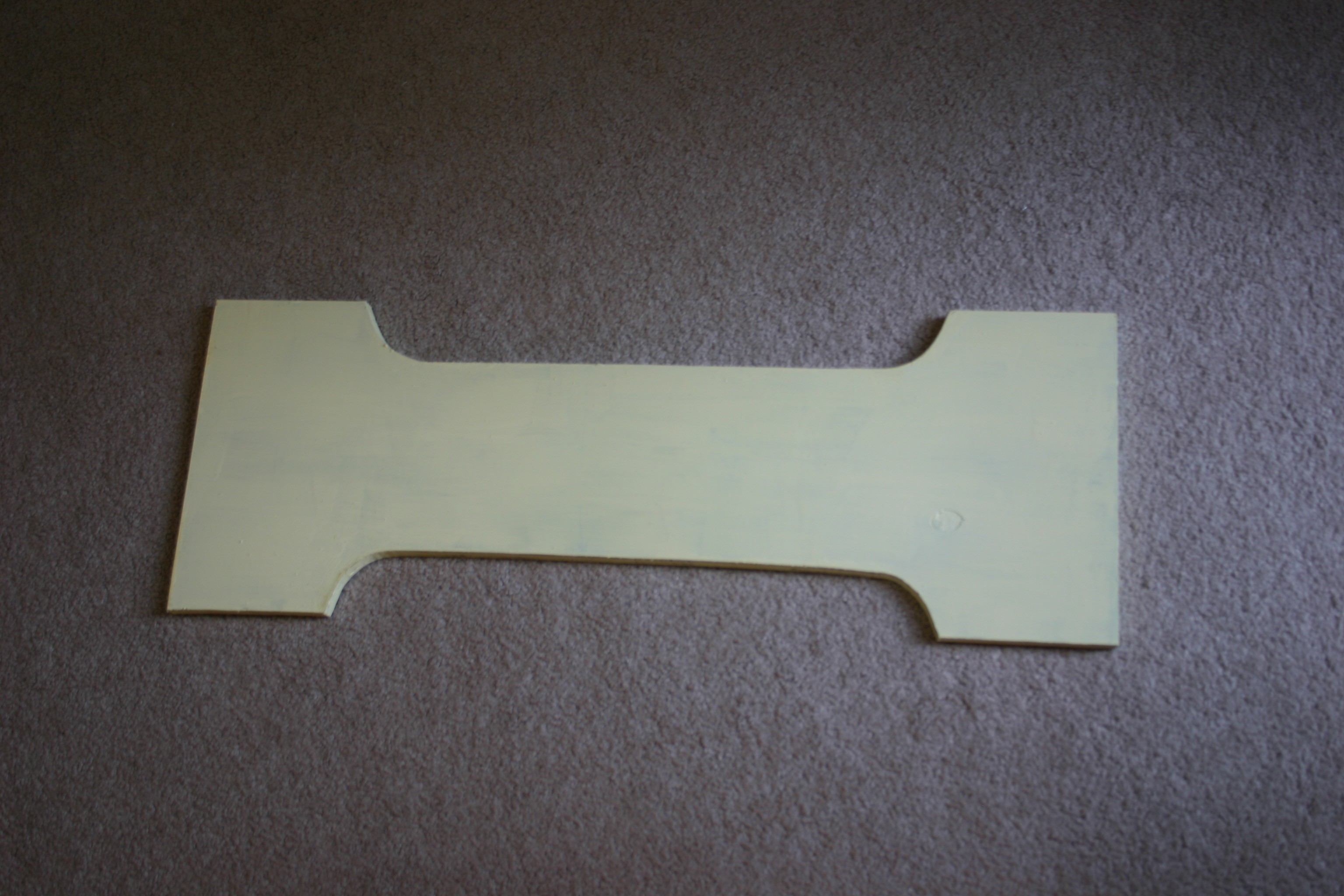
Build a stiff, low weight body
Take steps
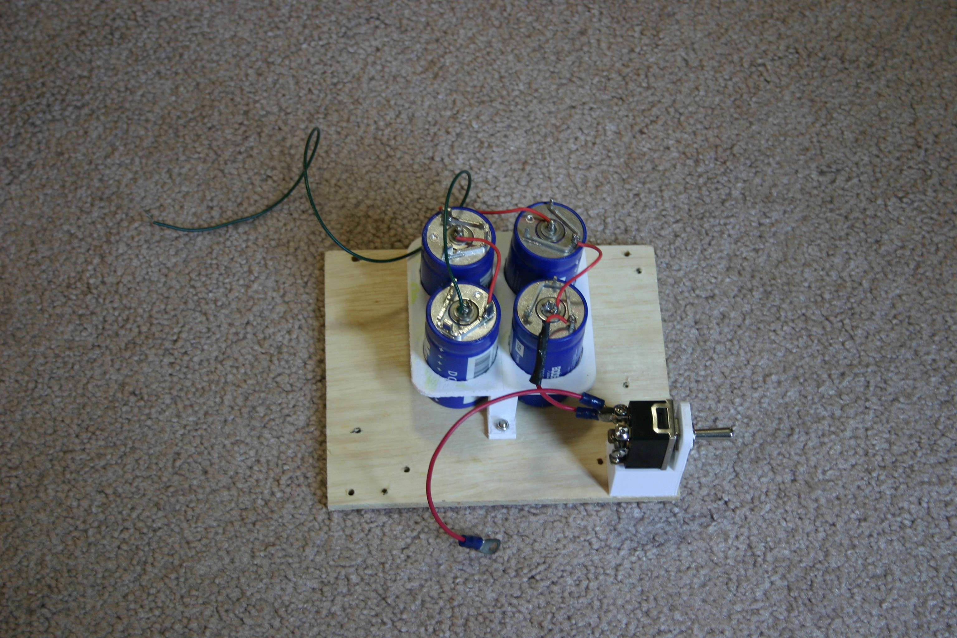
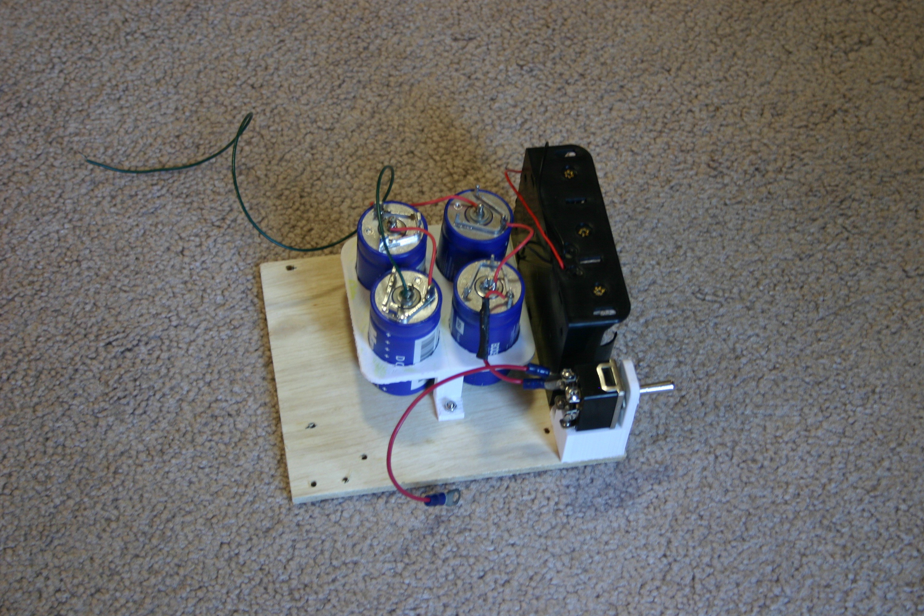
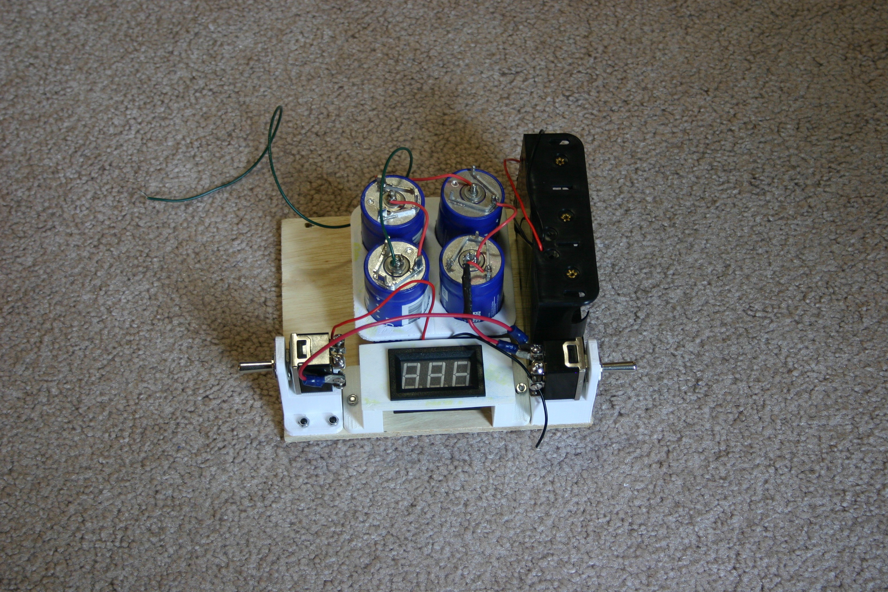
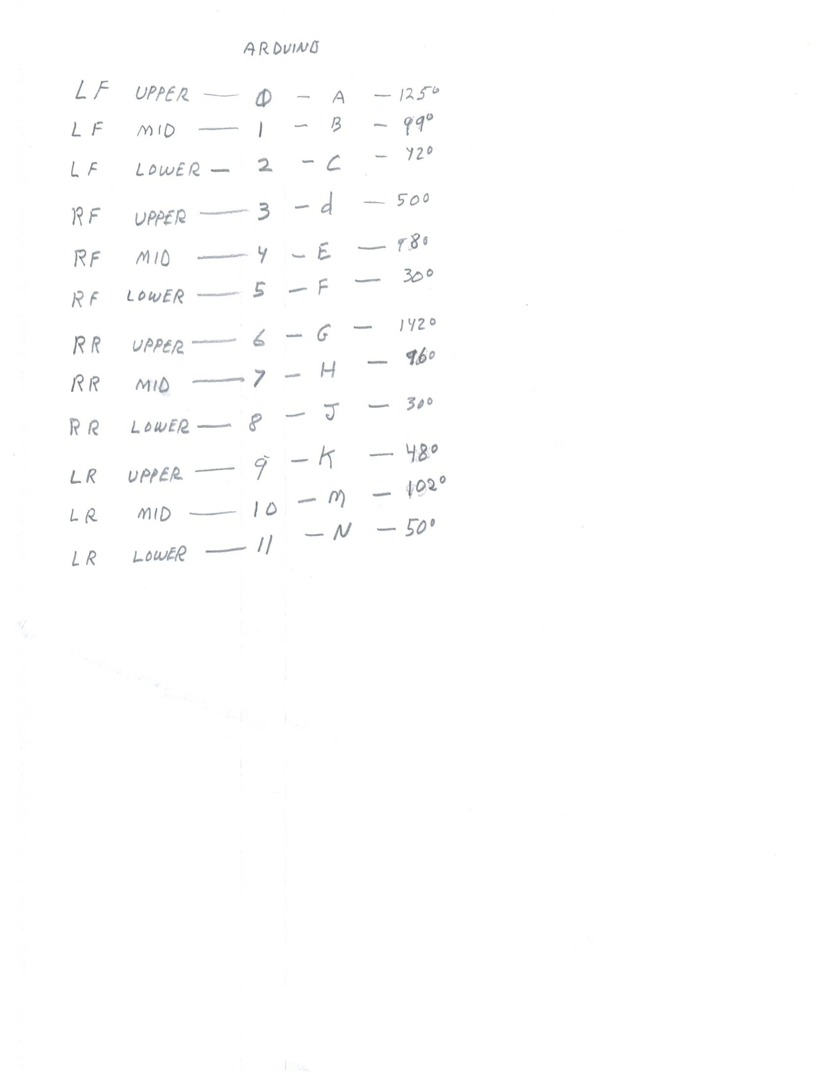
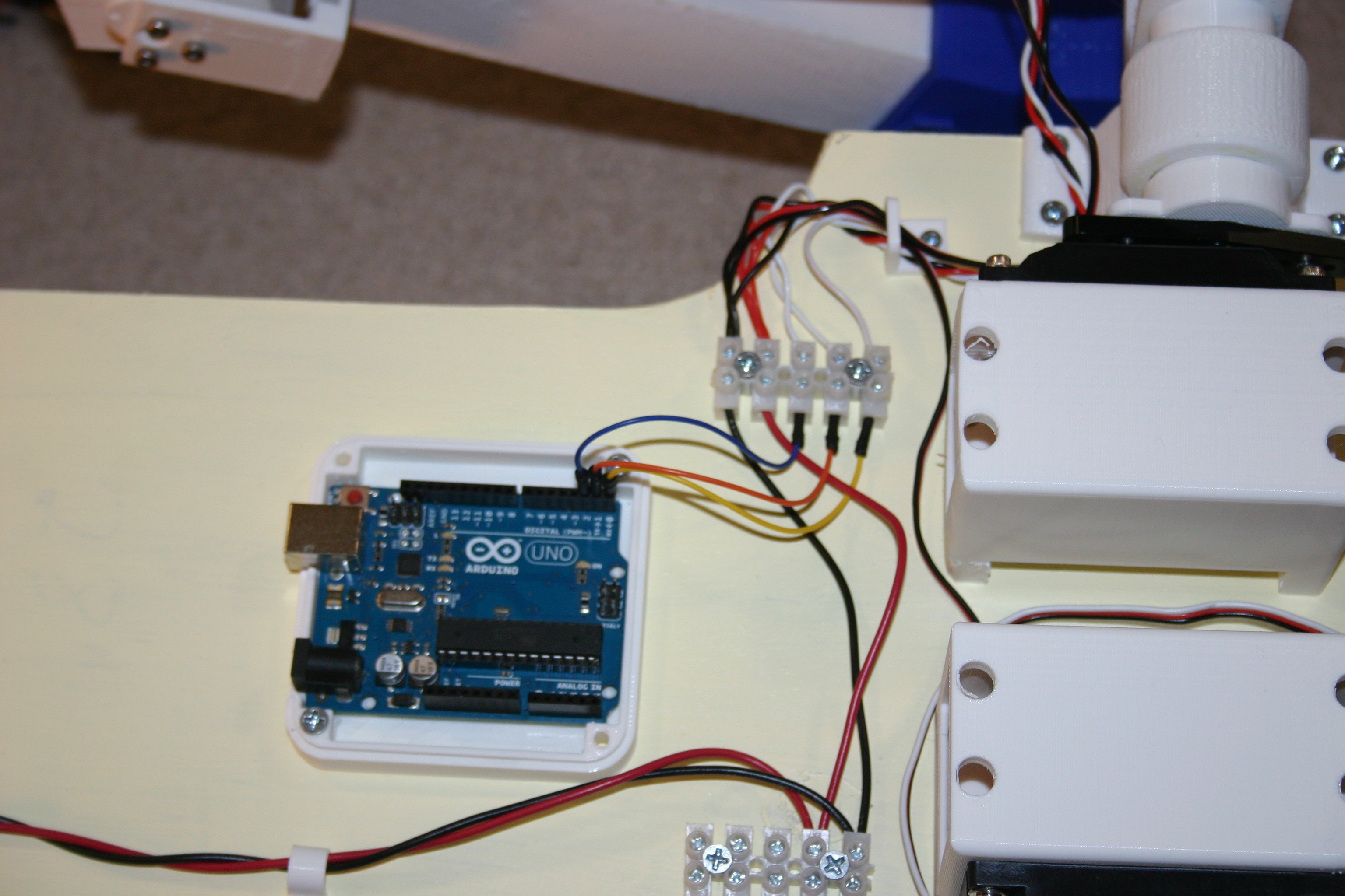
Add onboard power
Stand
Take steps
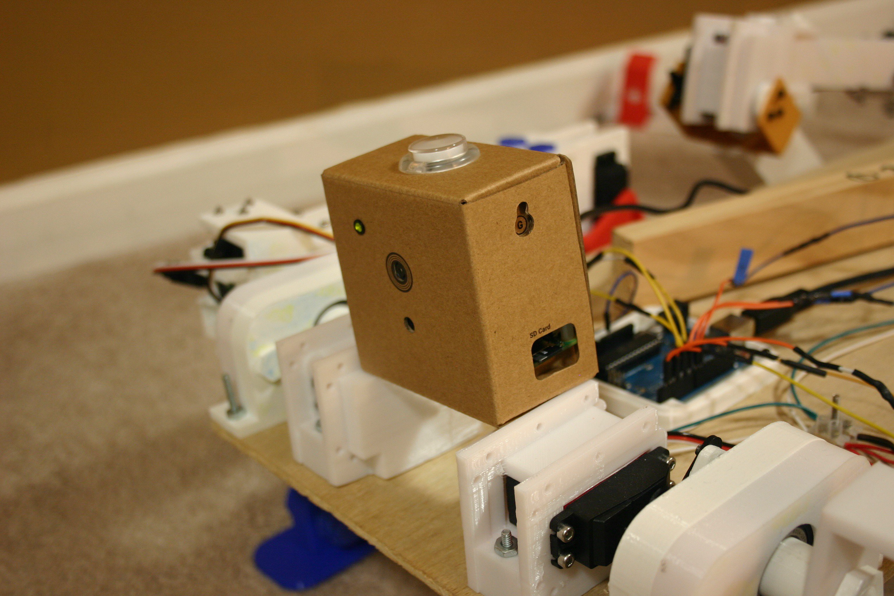
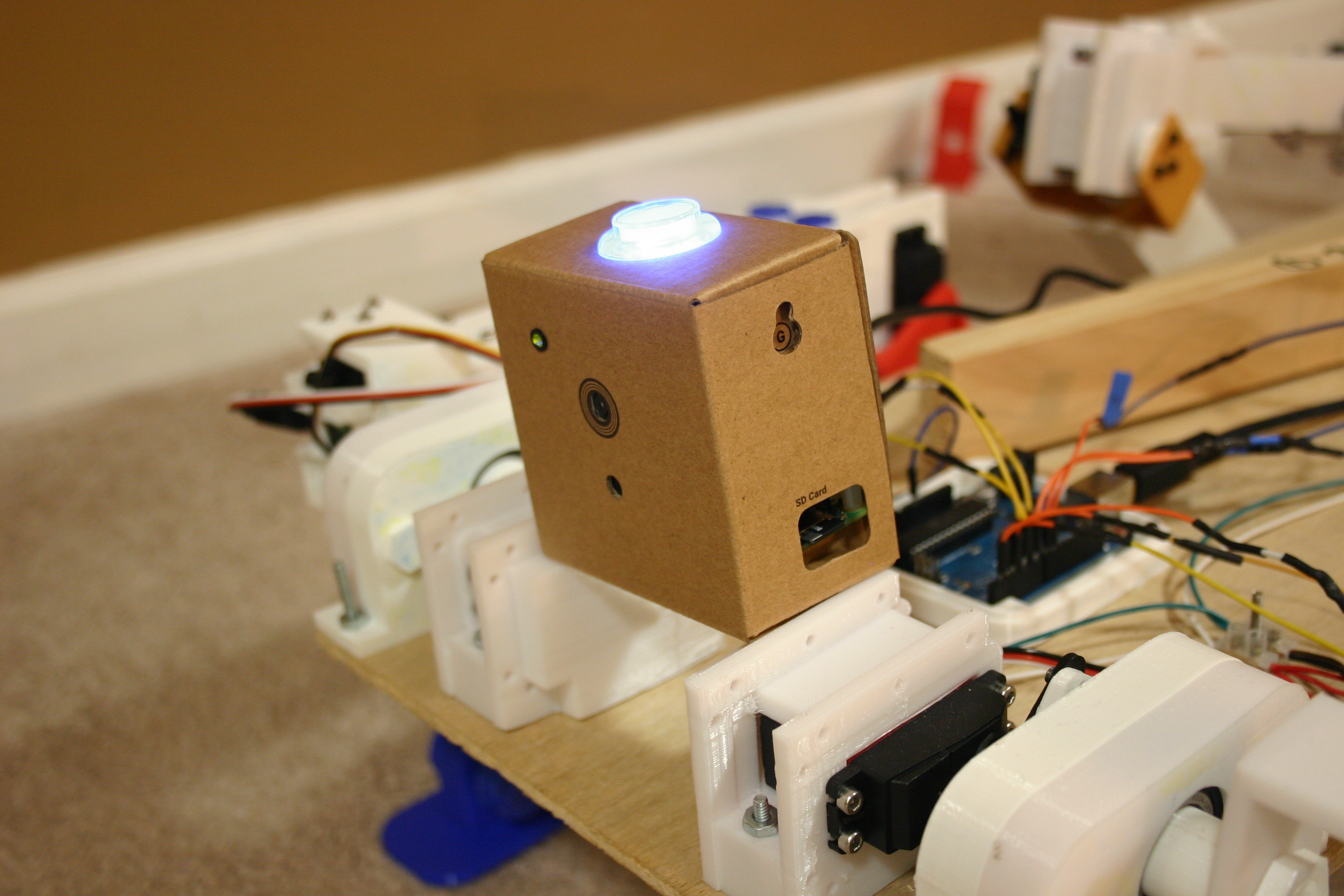
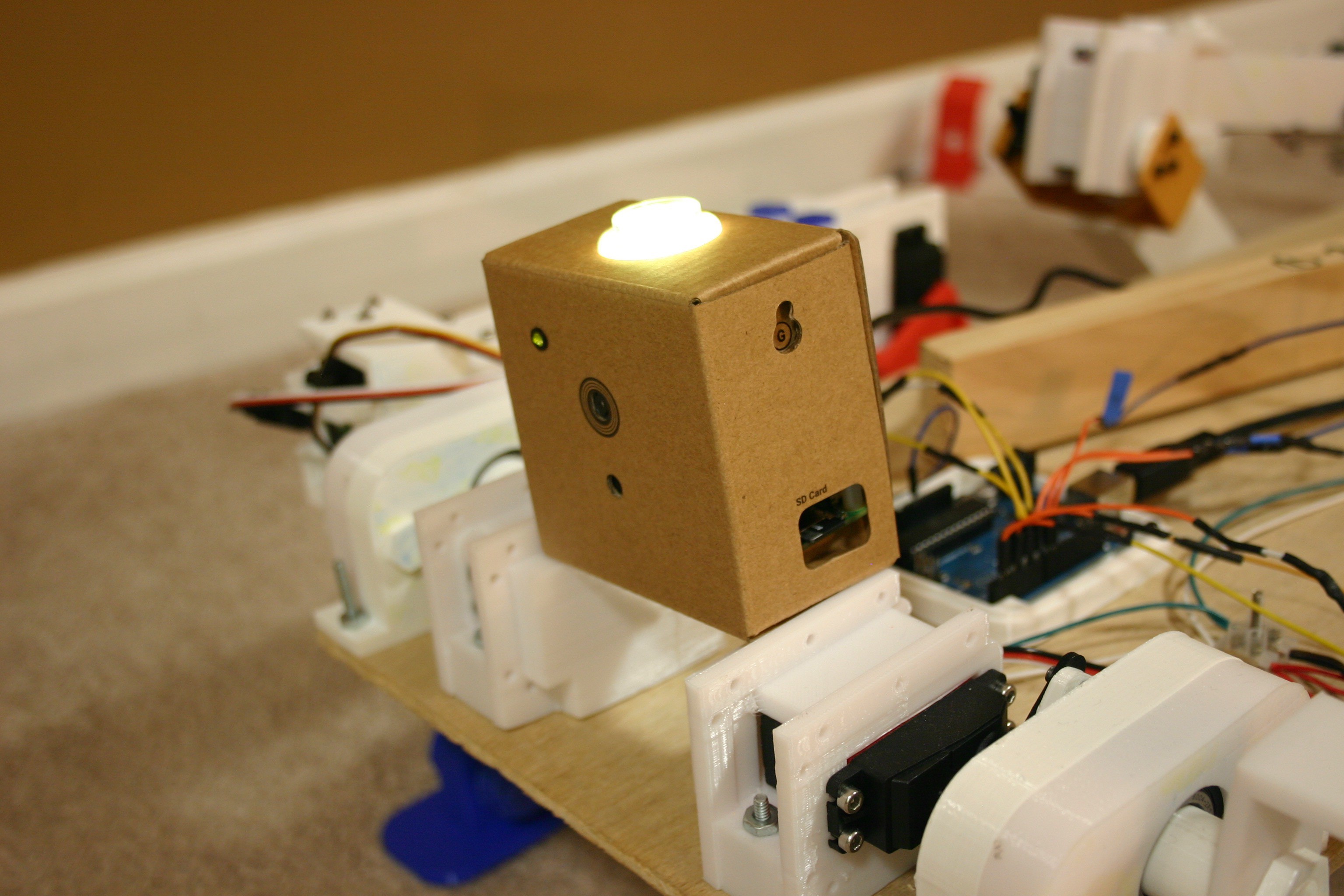
I had to show this . . . Google's AIY Vision Kit can be used to detect human faces or smiles (and probably other things). This will allow my dog to "know" that someone is there and if they are smiling. More information can be found in log number 10, "Google AIY Vision."
Spot Mini is an amazing (perhaps scary) robot dog built by Boston Dynamics--not for sale.
If you want to purchase something similar, a company in China produces a research platform for around $30,000. Another legged platform, Anymal, can follow you into an elevator.
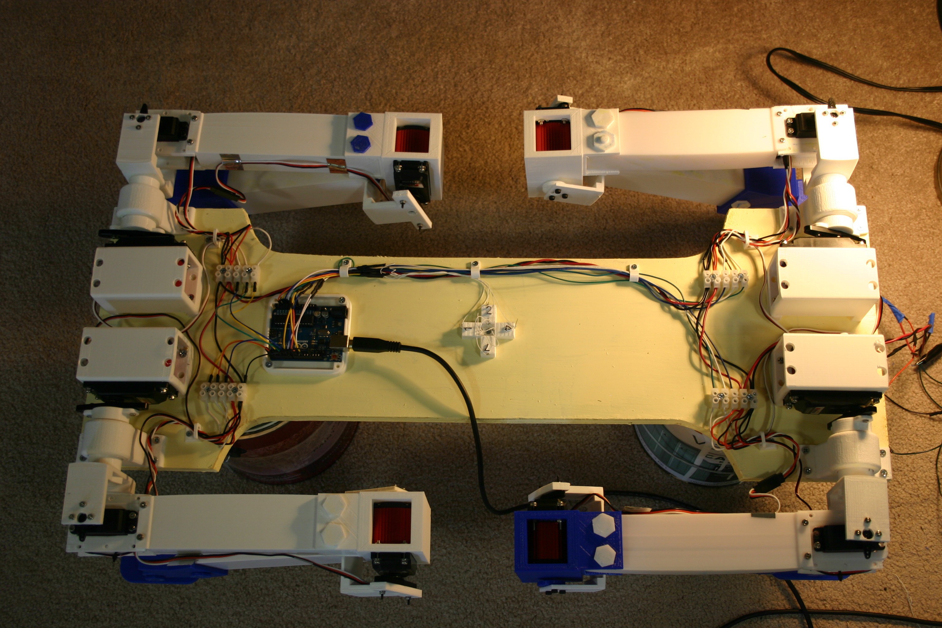
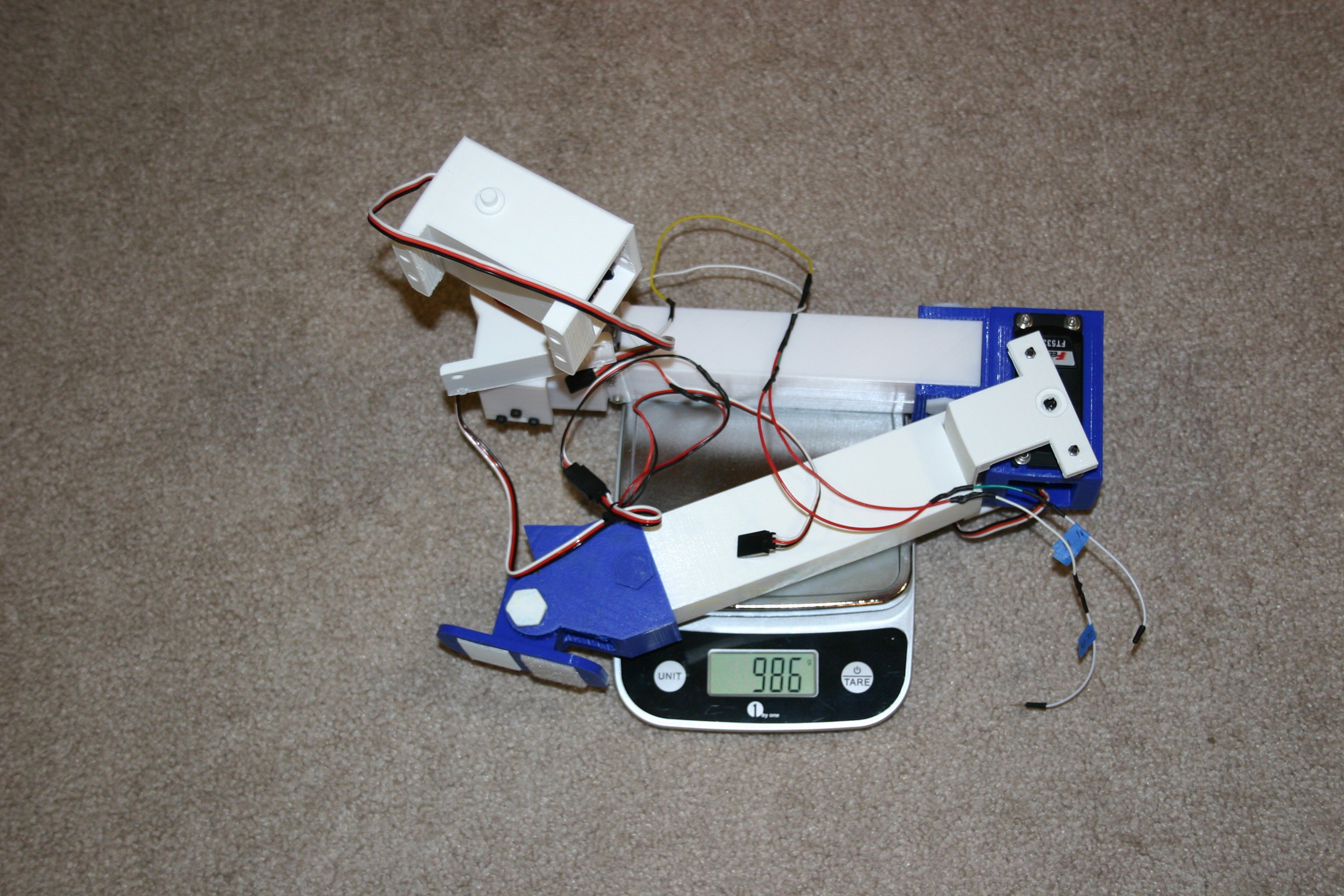
Using a 3d printer, off the shelf servo motors, an Arduino and a couple of ultracapacitors; I have started something along the same line--but the cost is more like $300.
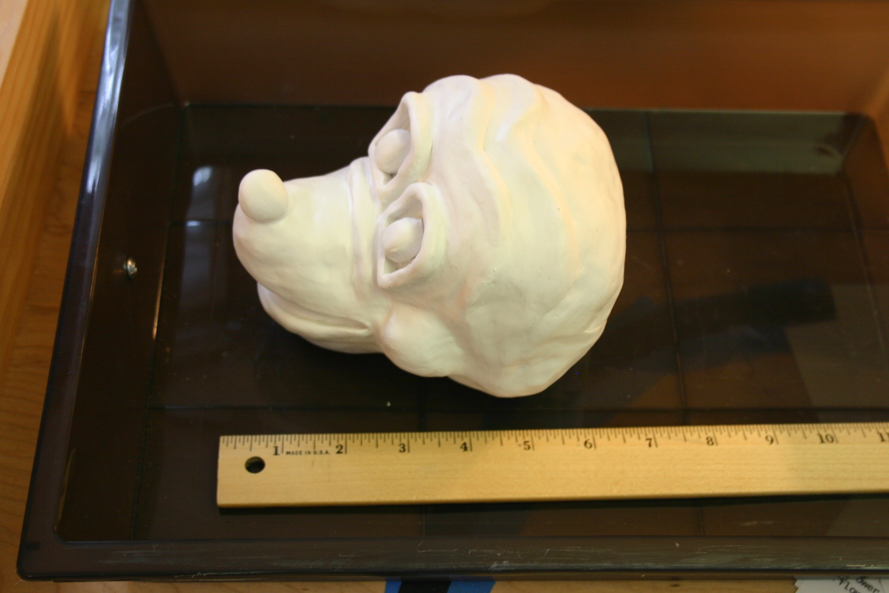
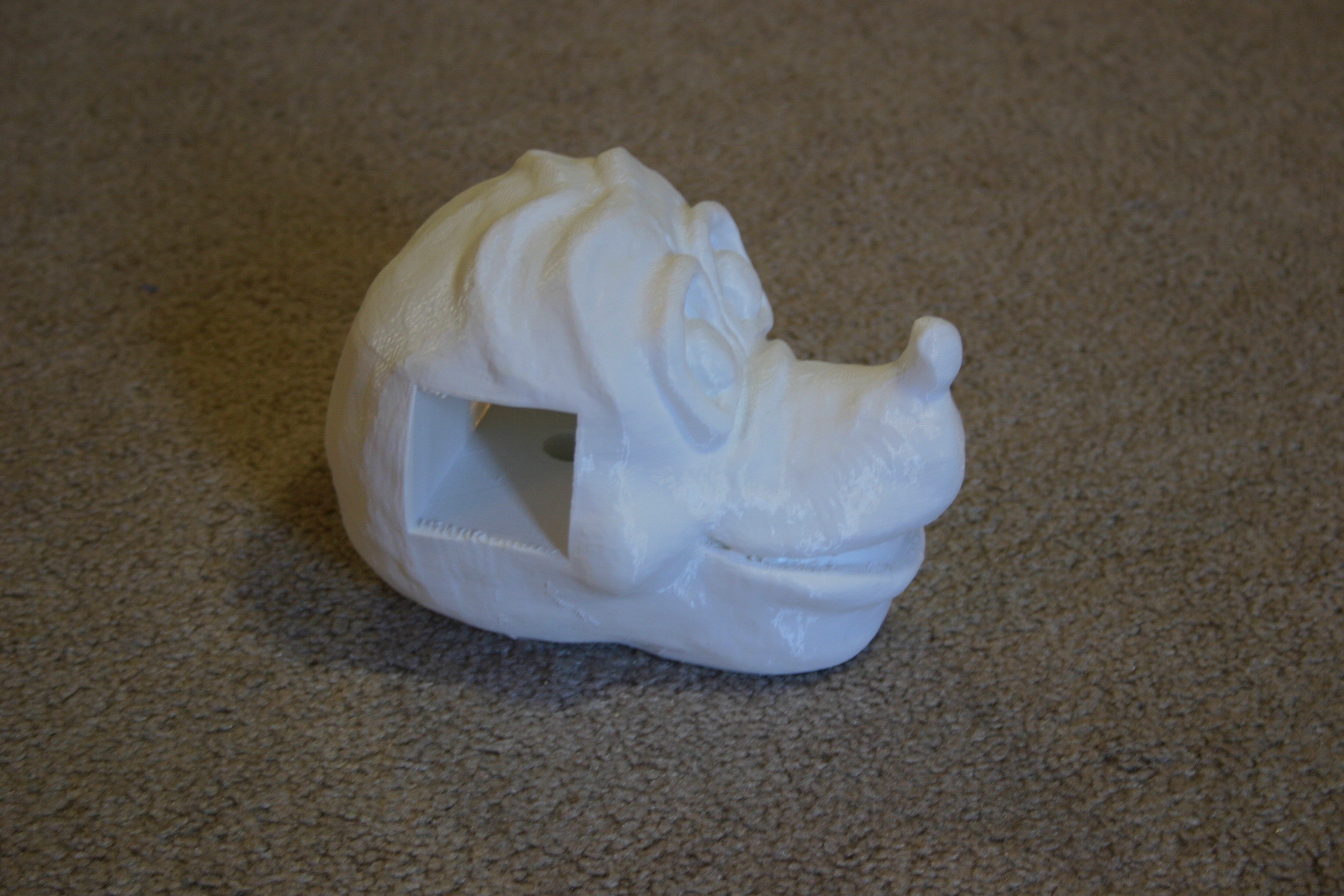
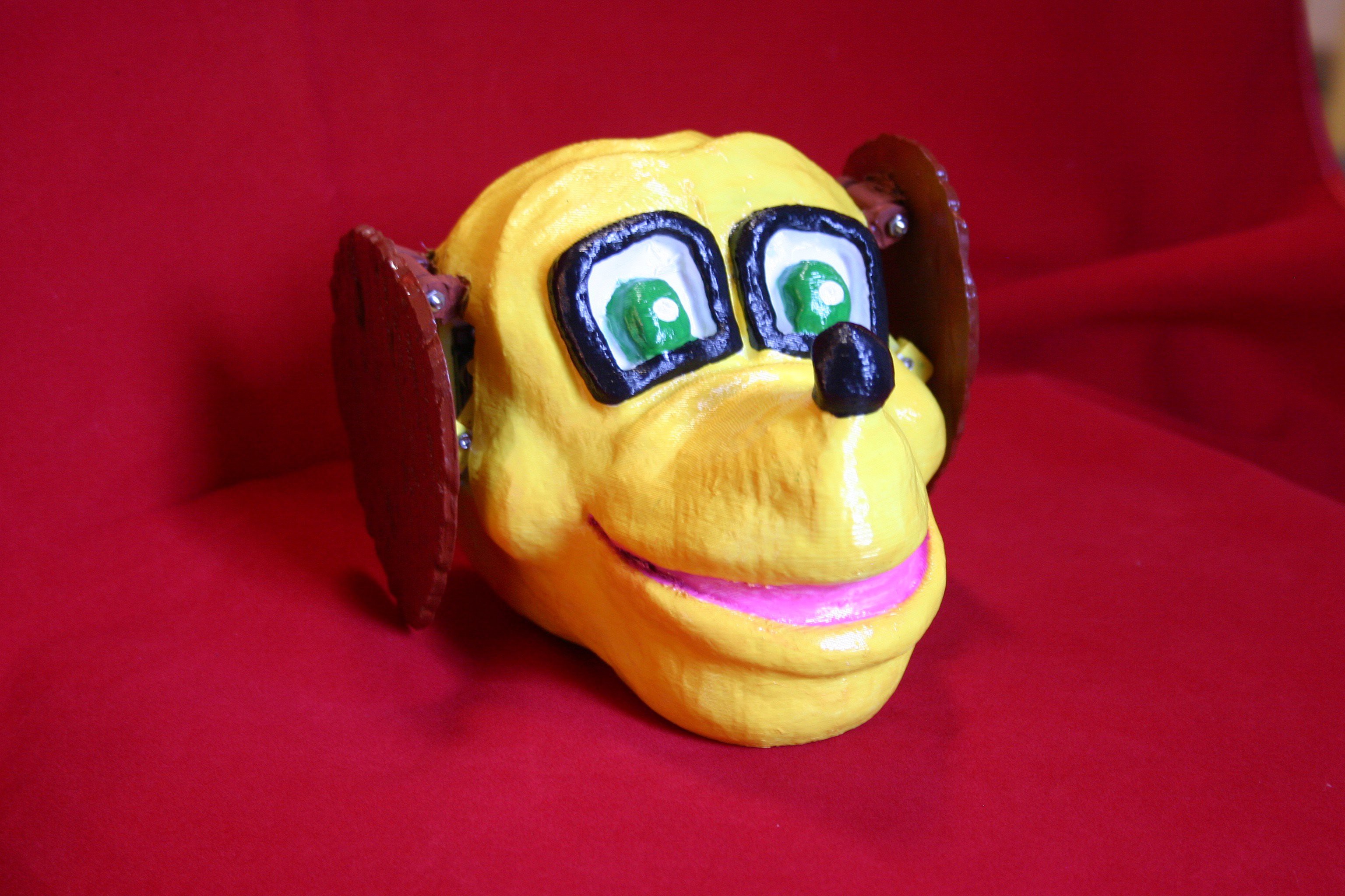
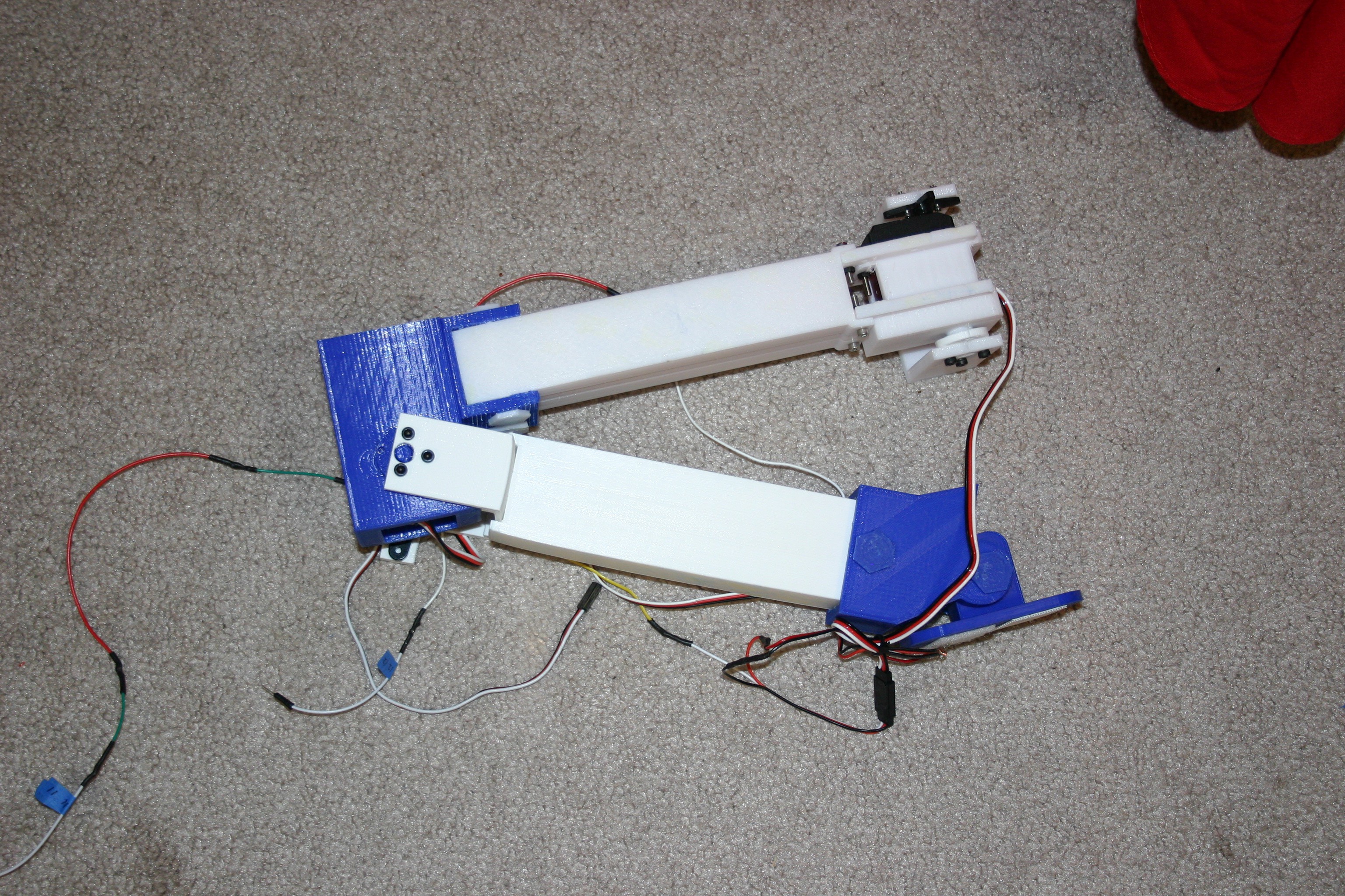
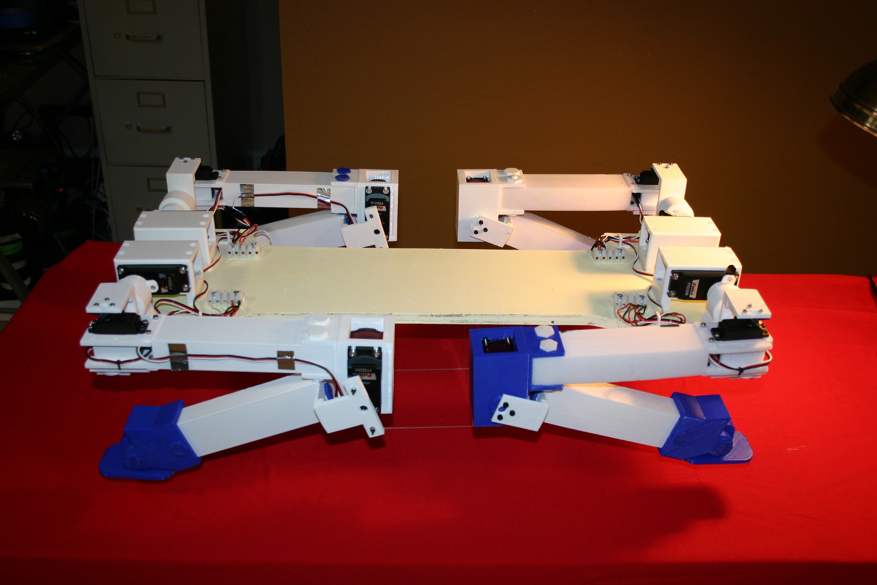
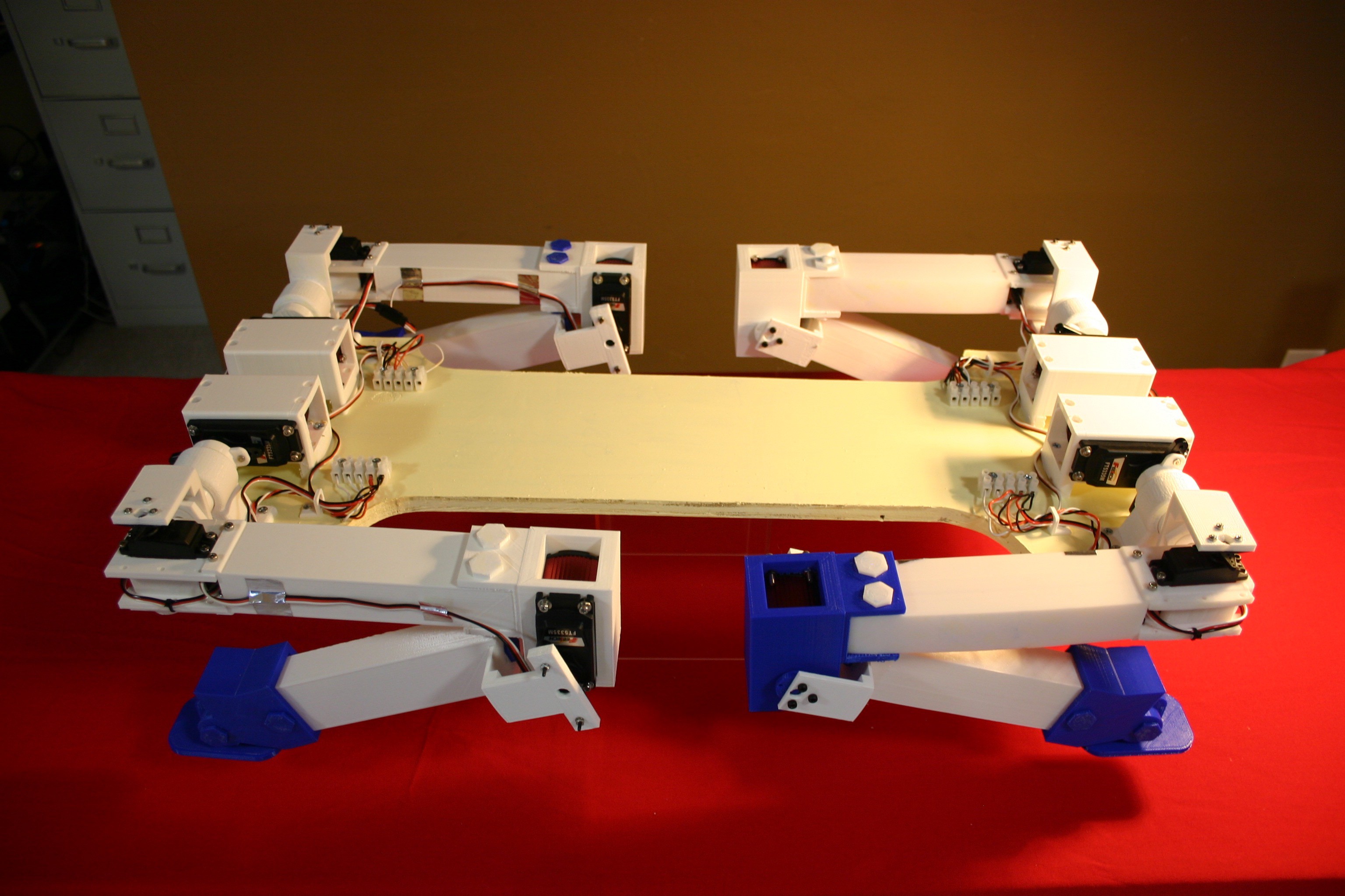
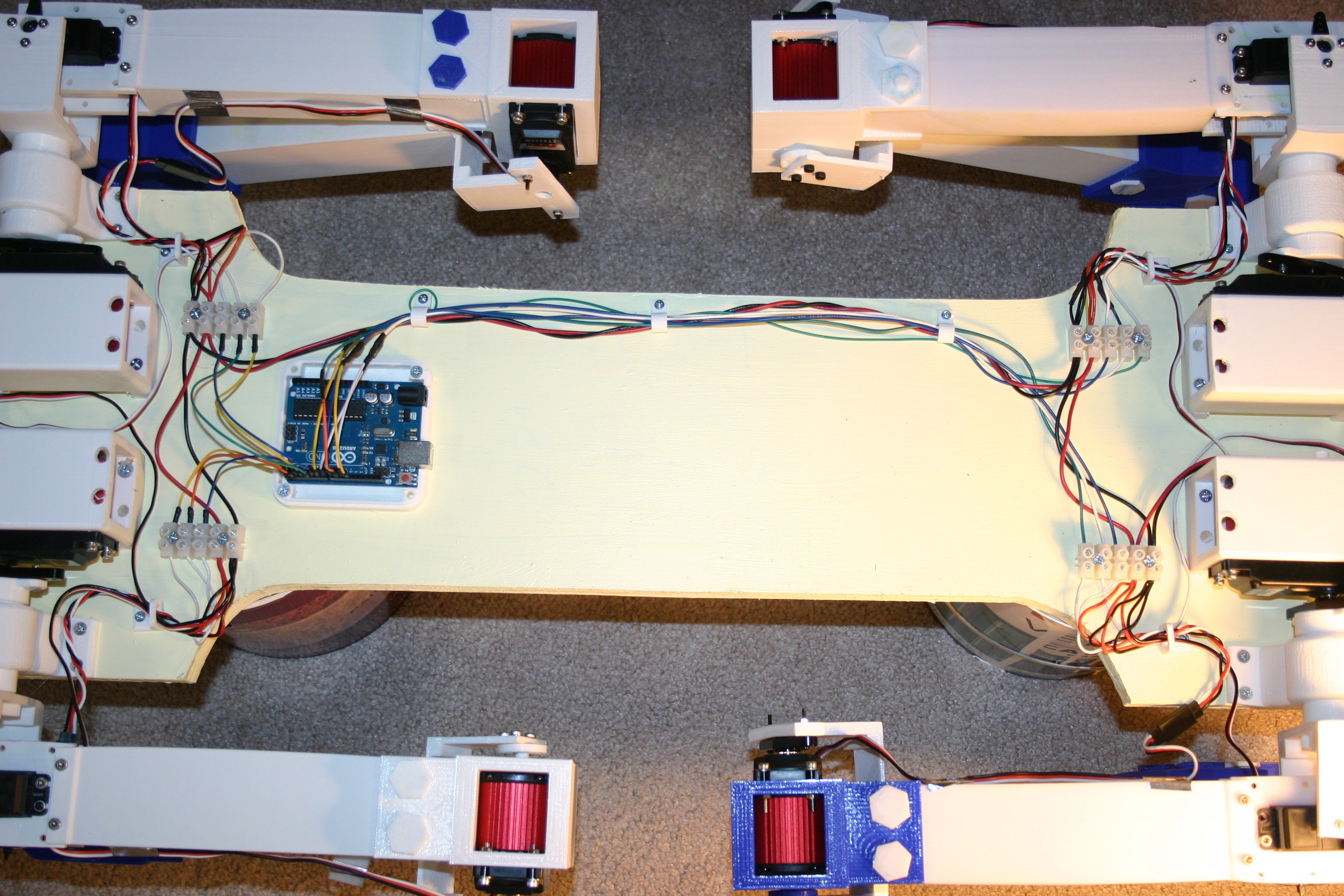
She's young and shaky, but my dog can now stand. The body is longer and the rear legs reversed--look to my log, "The Forces Are Not All With Me."
Here's where we "stand" on March 28.
This is where it started.
Here's where I am on March 16.
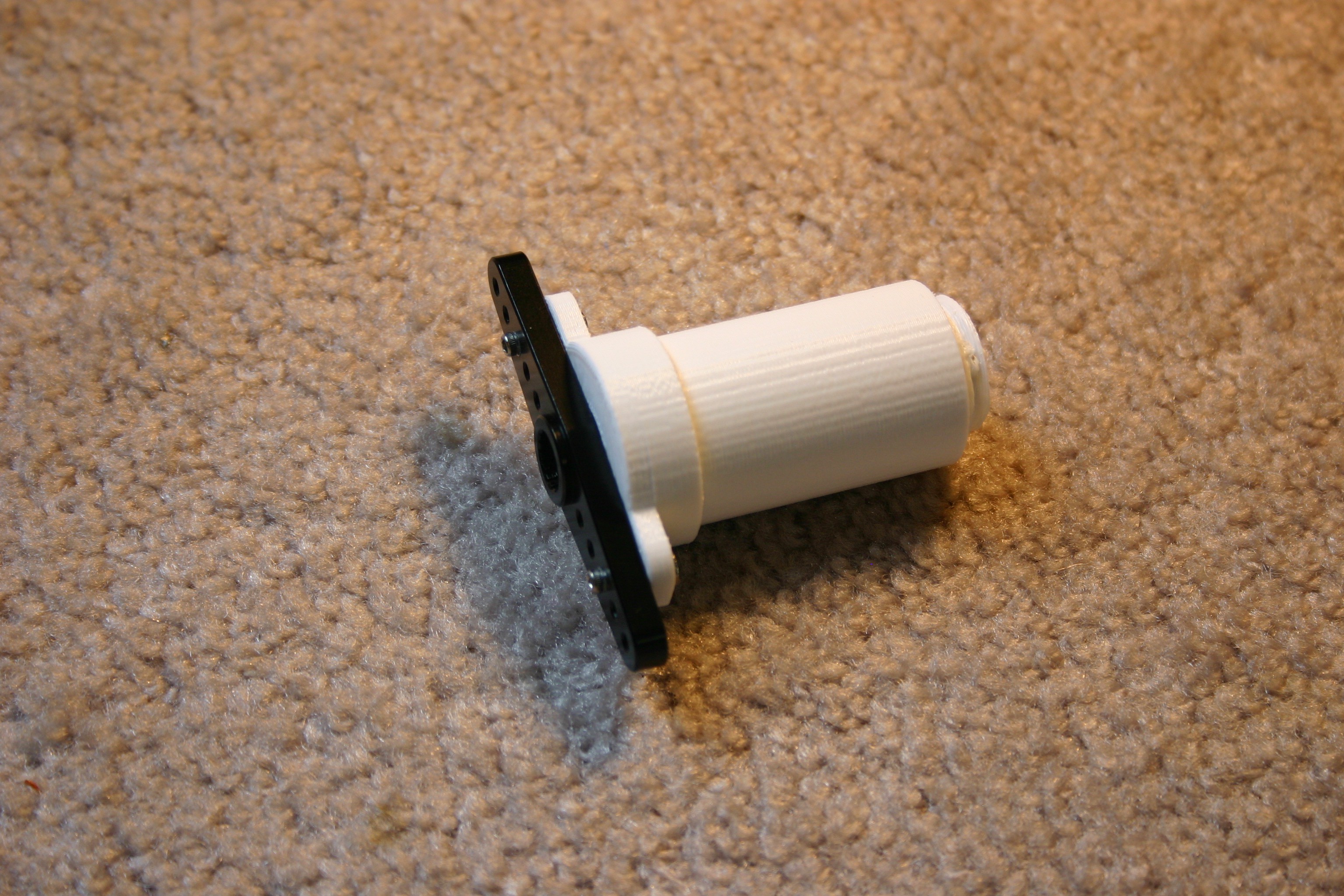
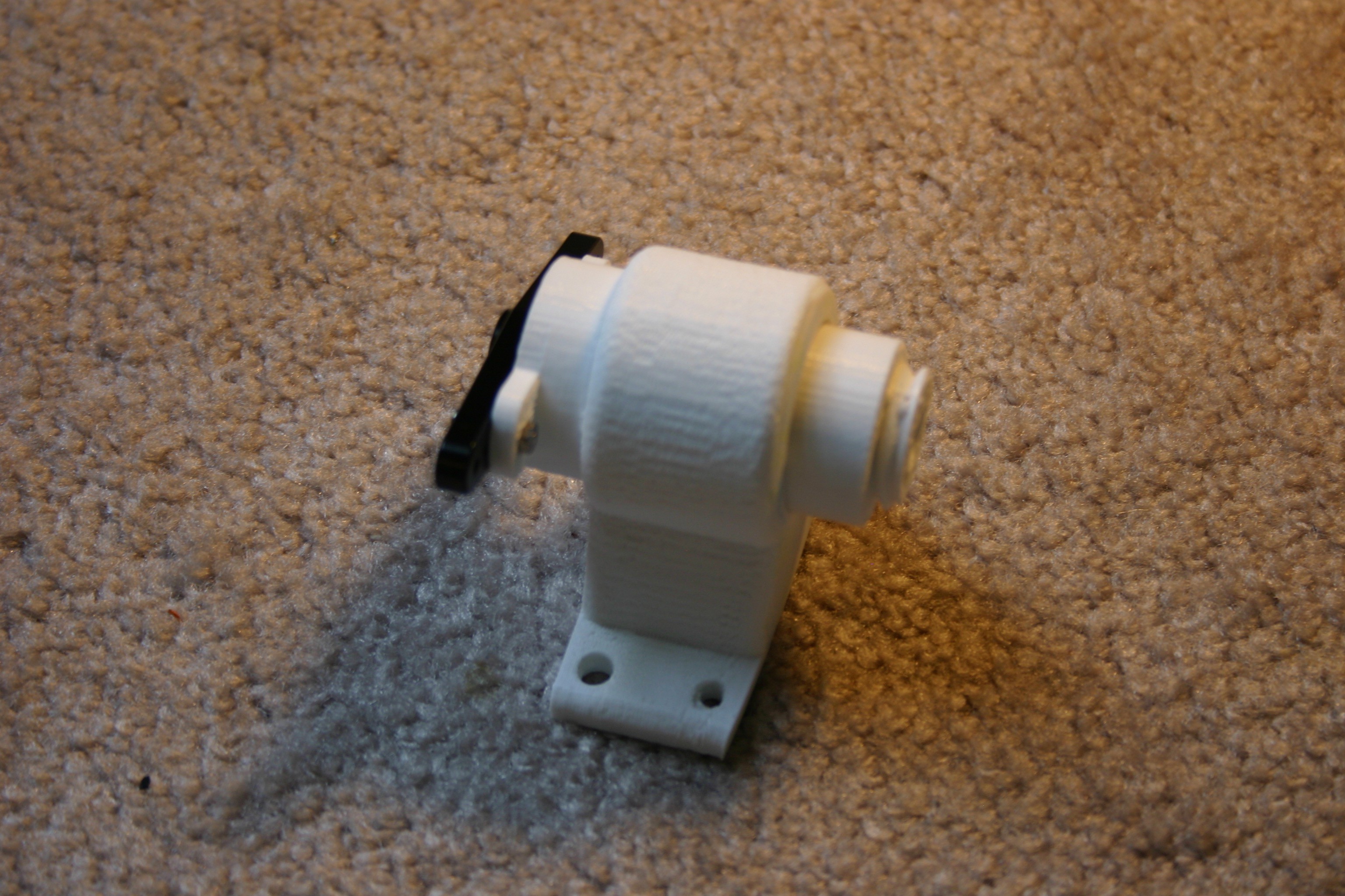
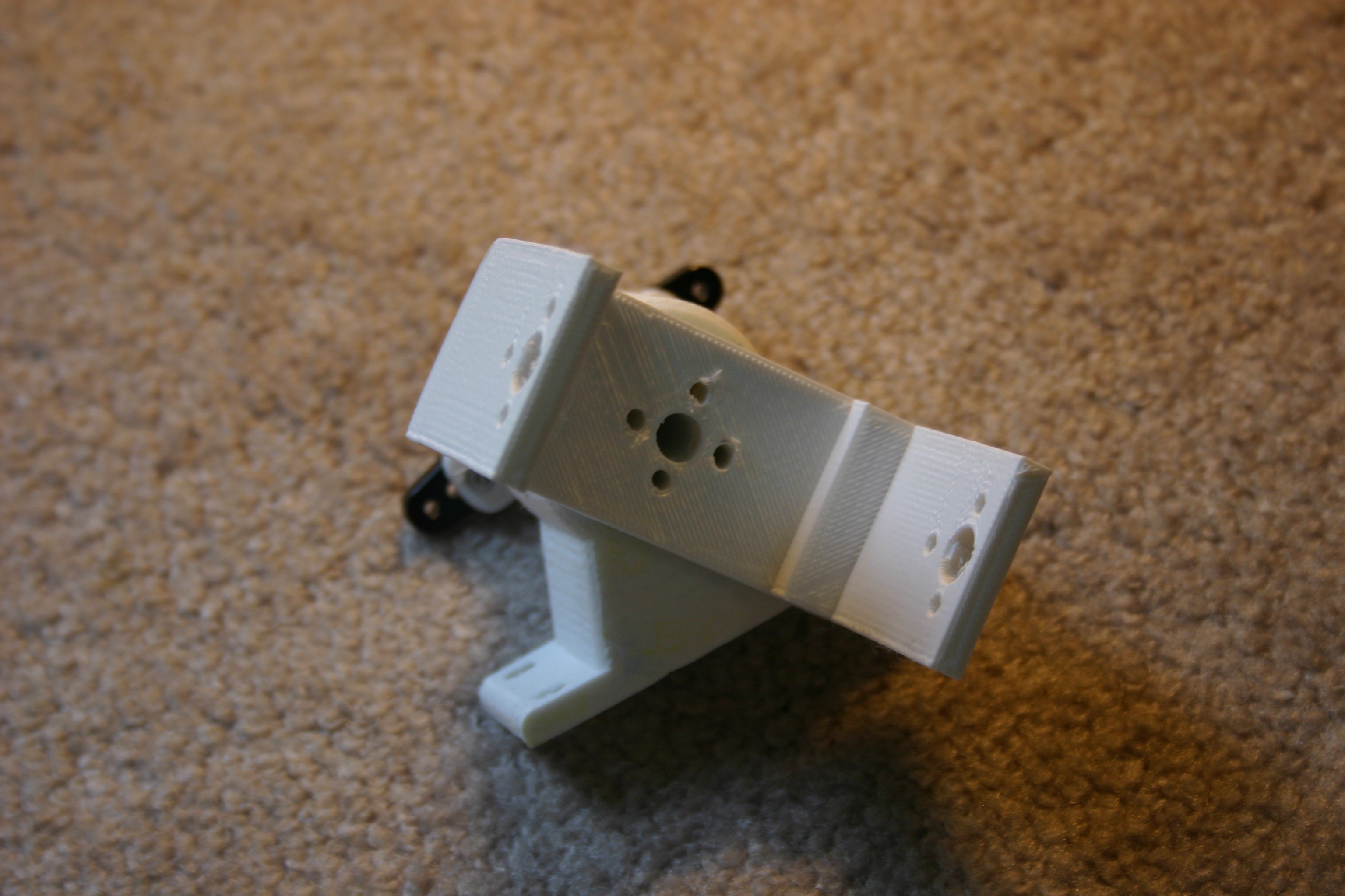
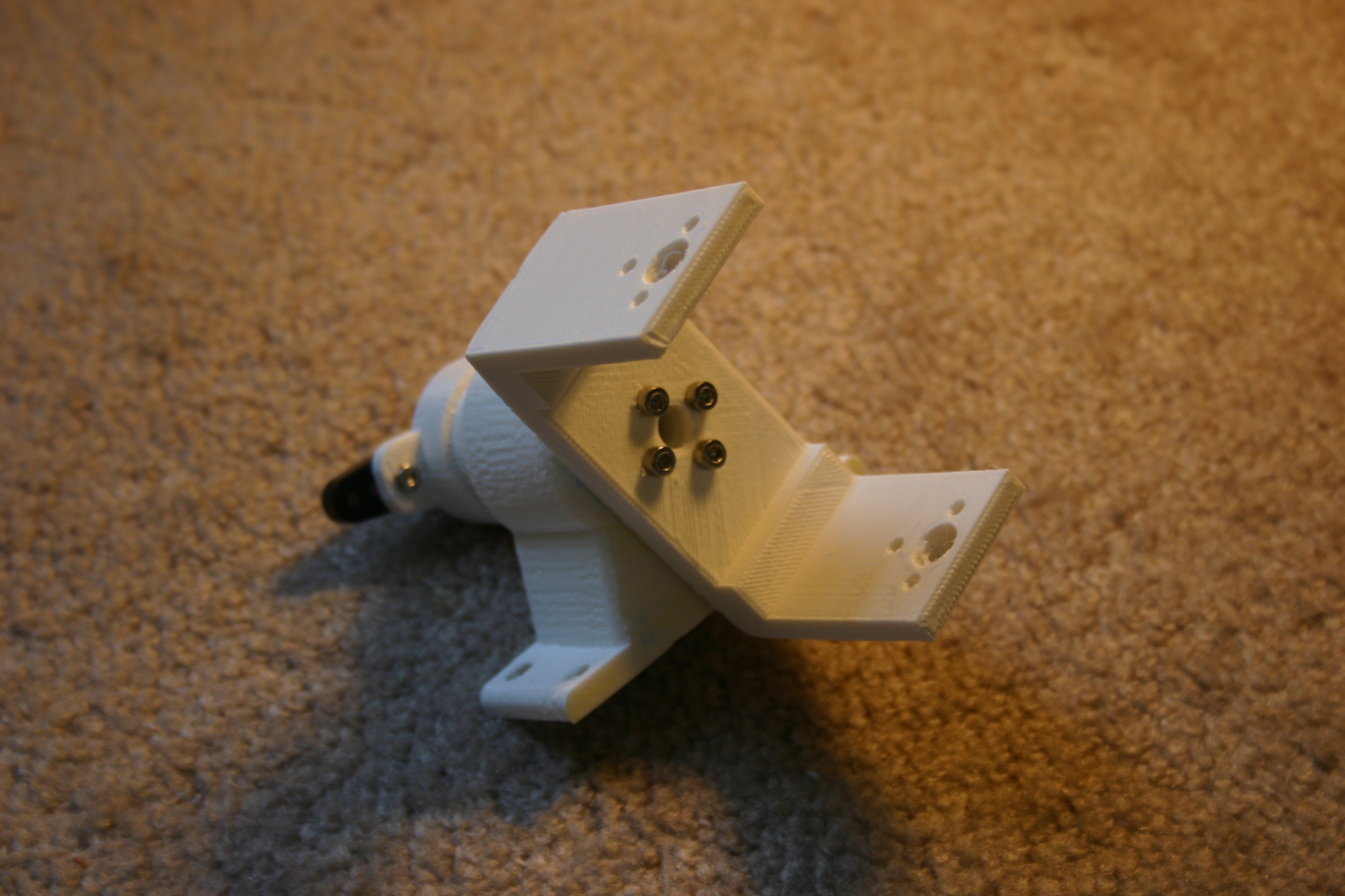
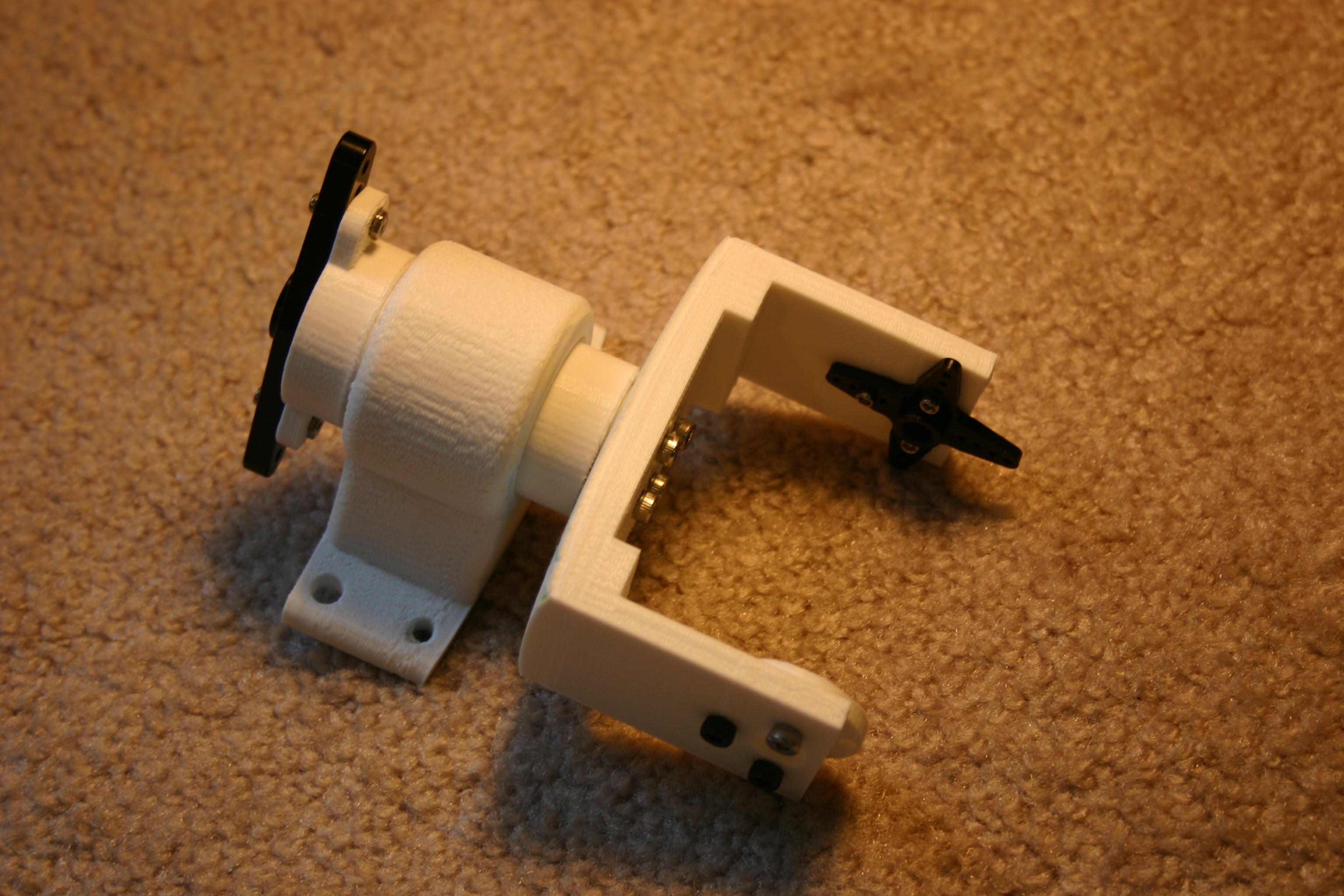
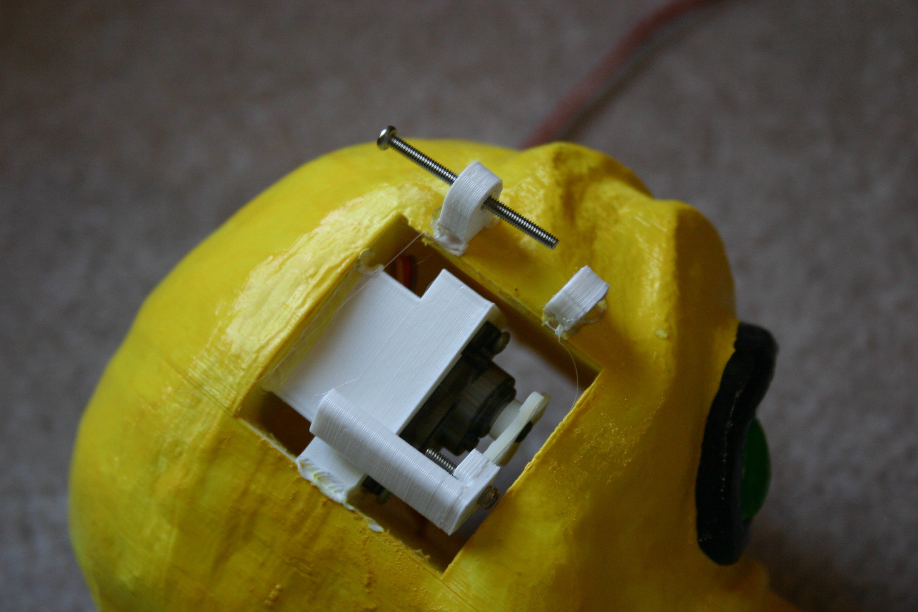
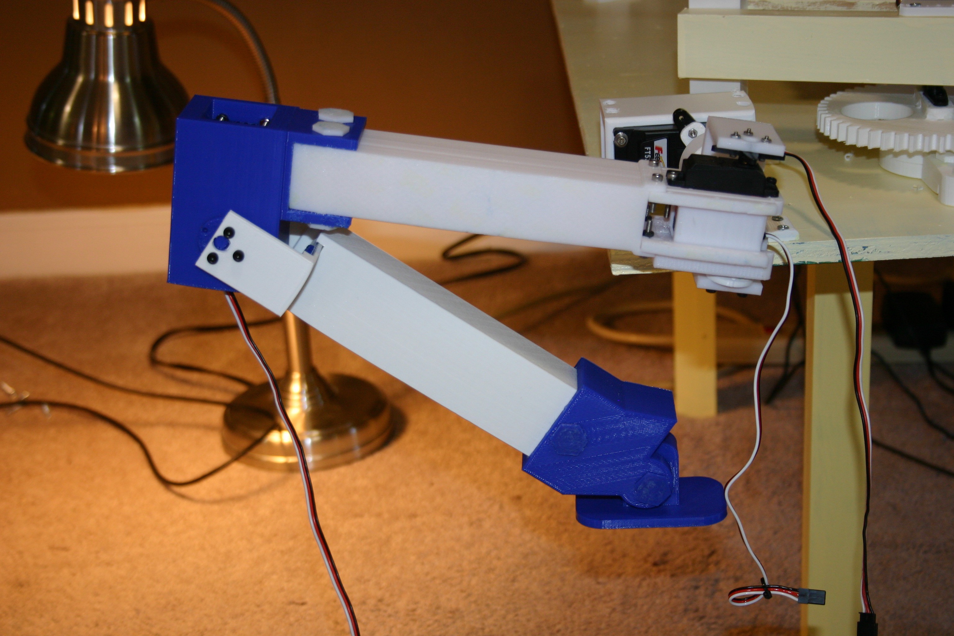
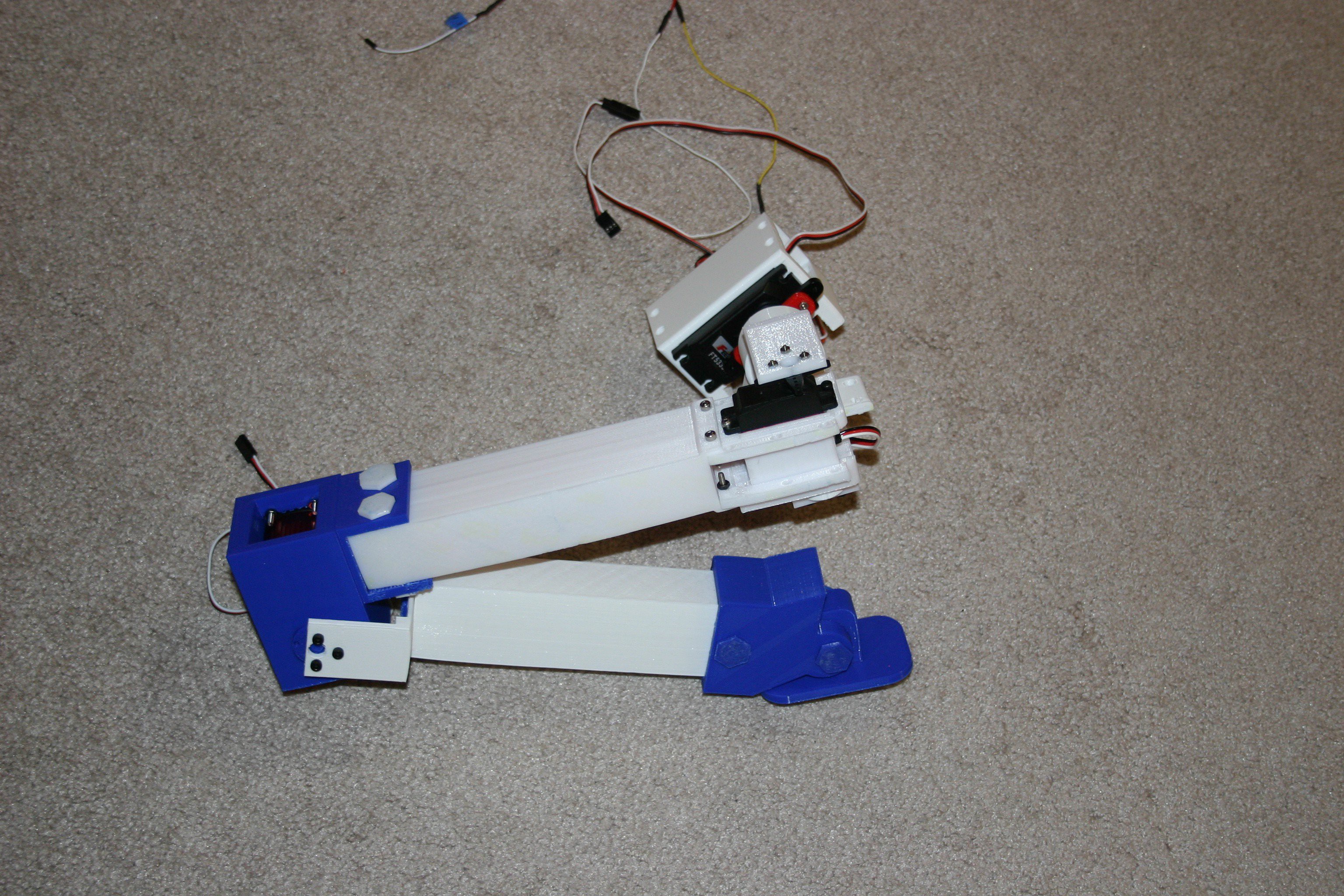
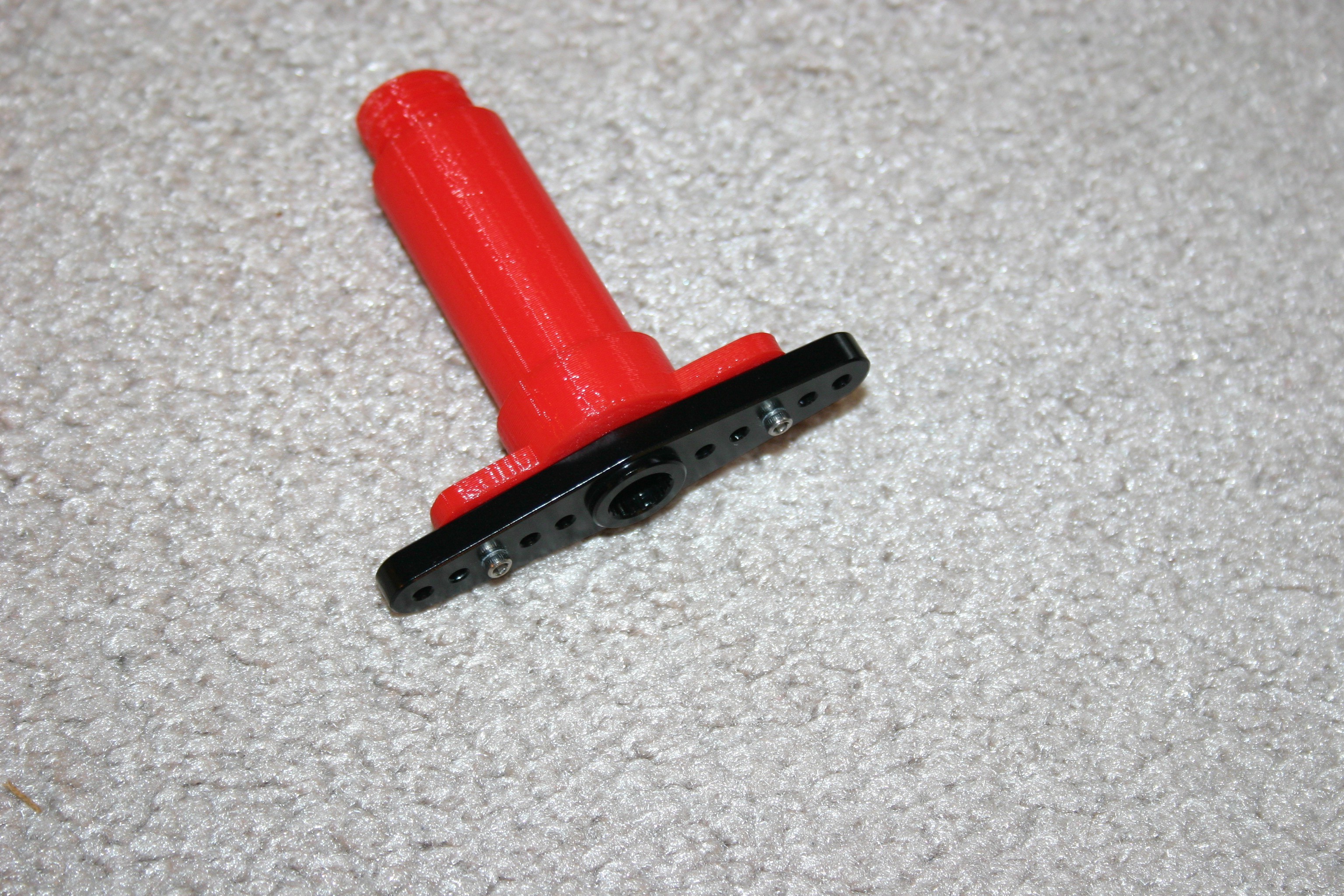
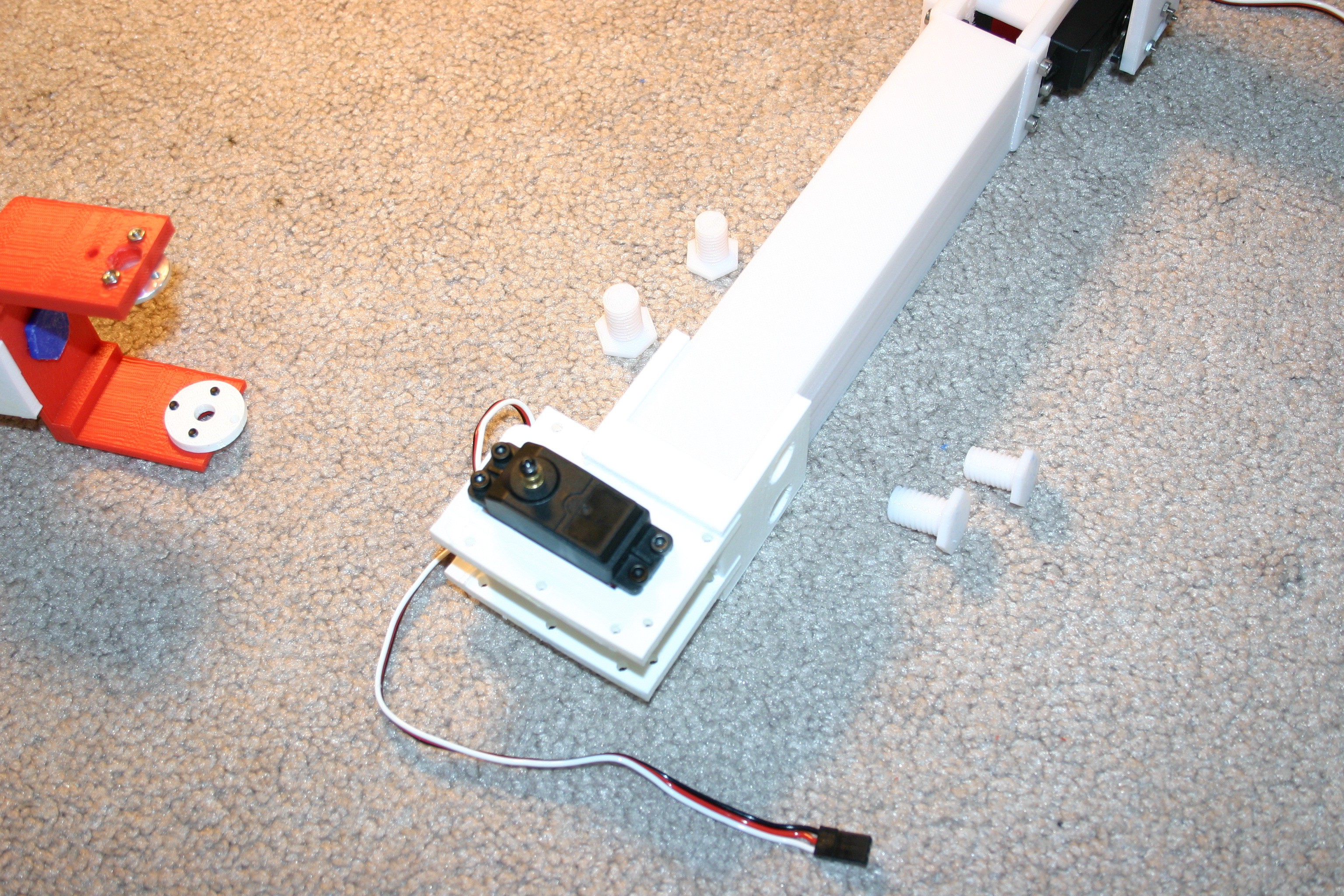
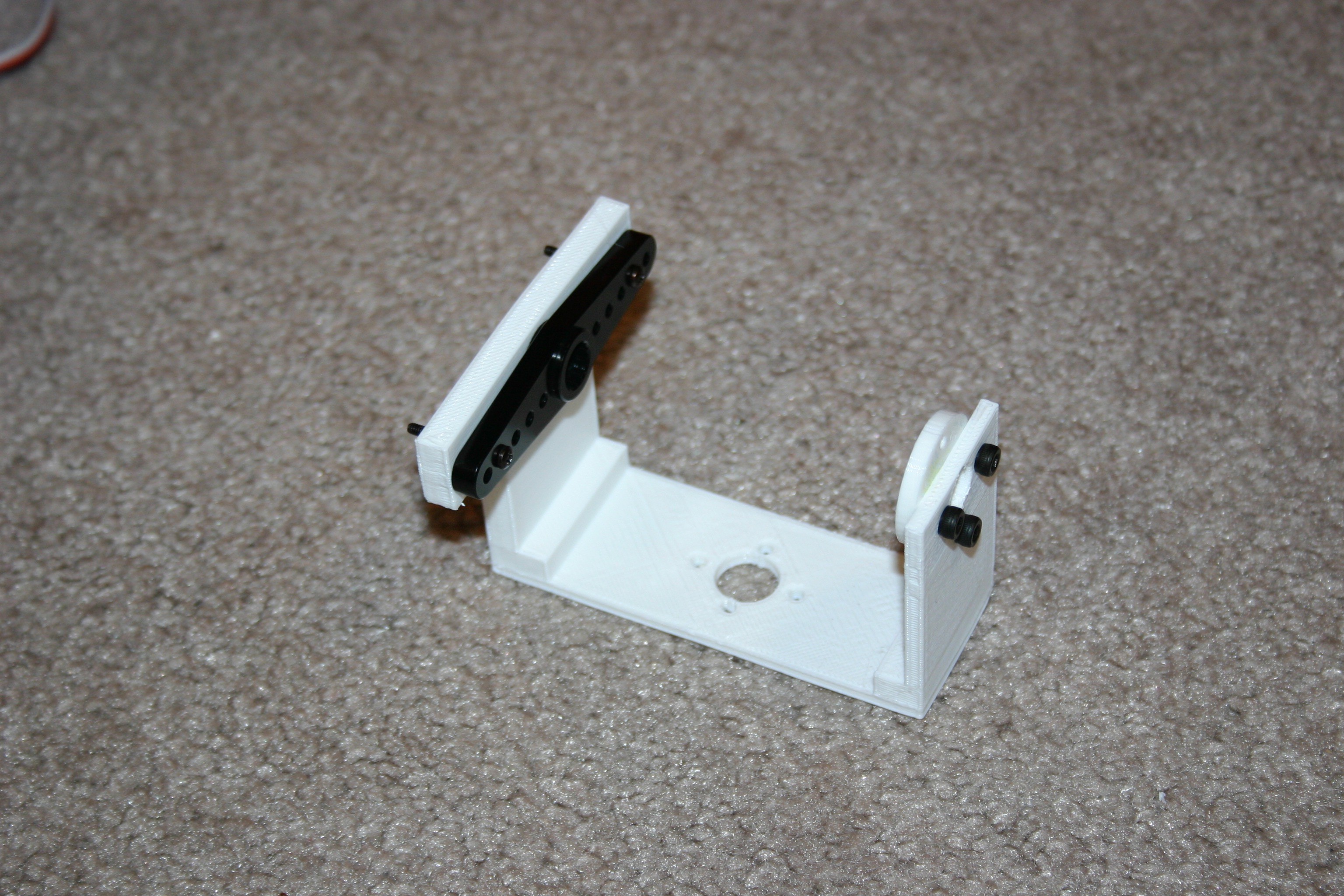
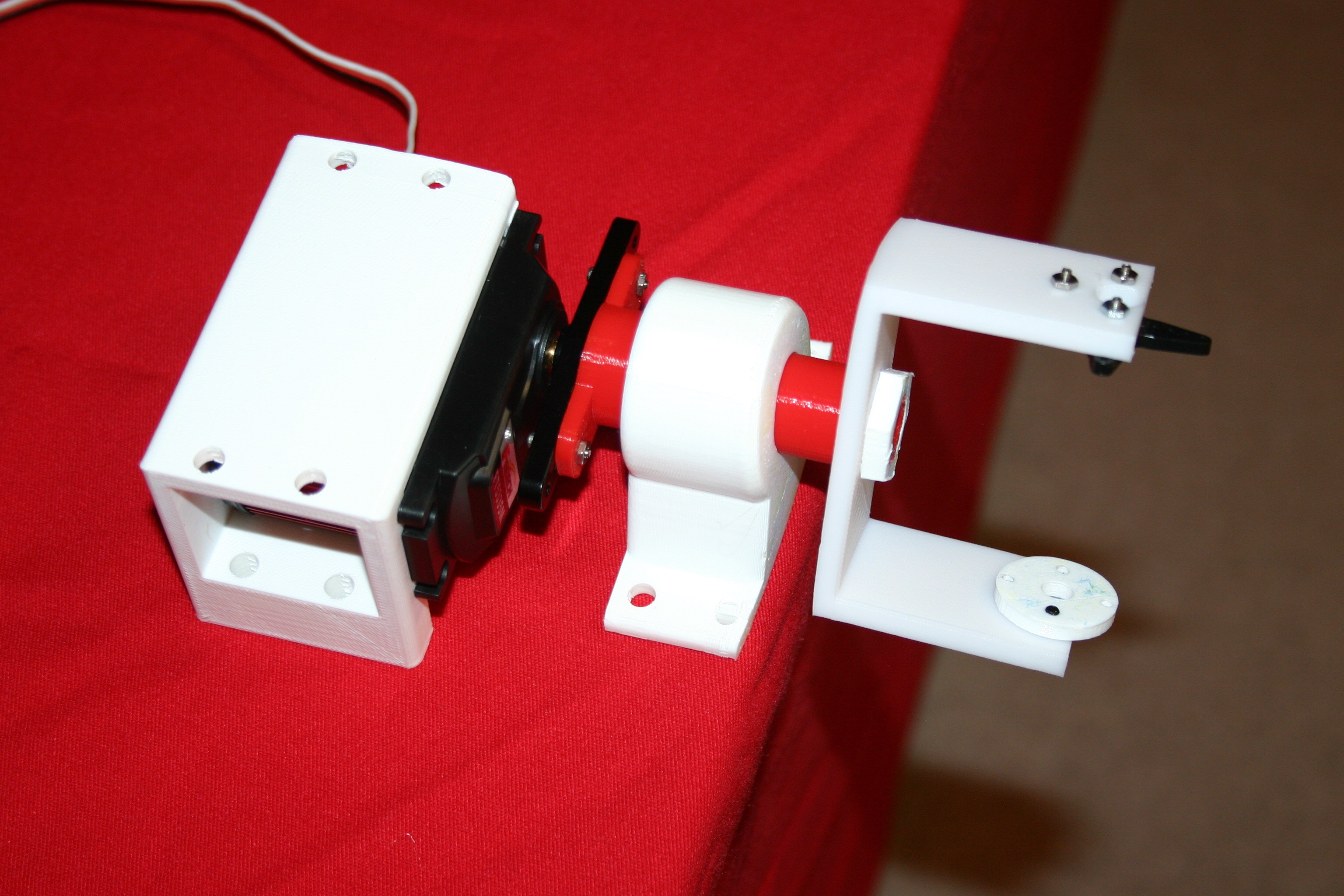
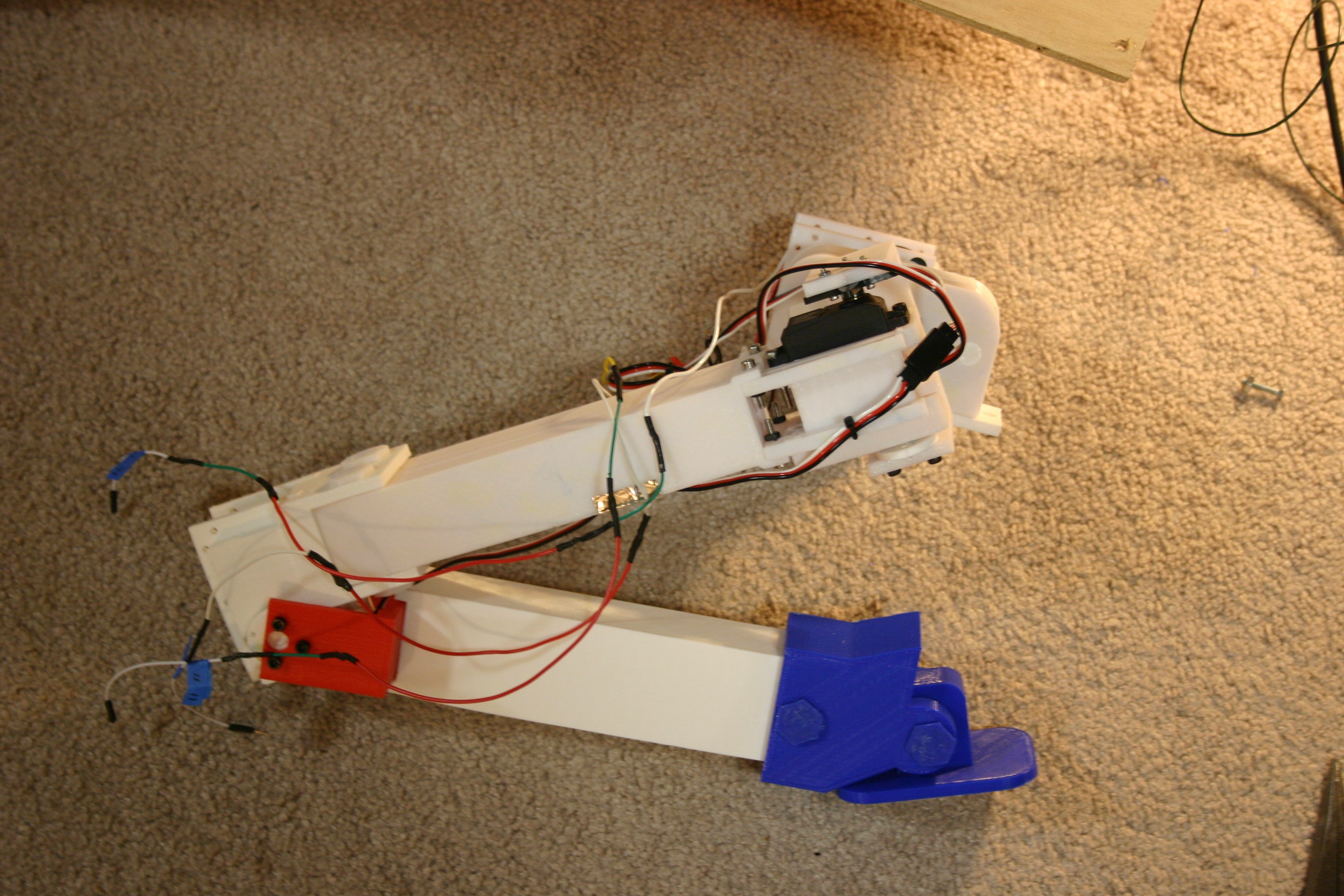
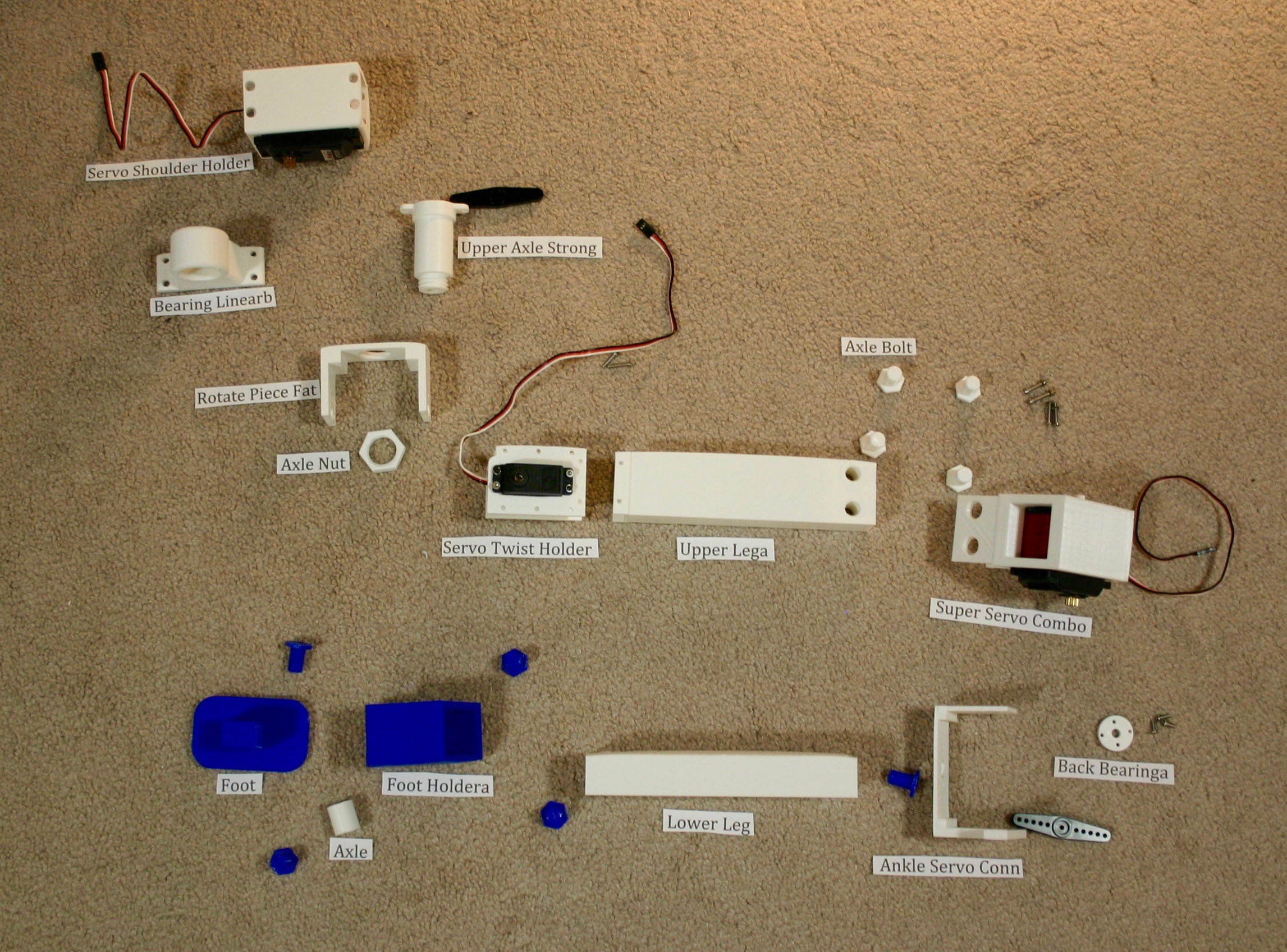
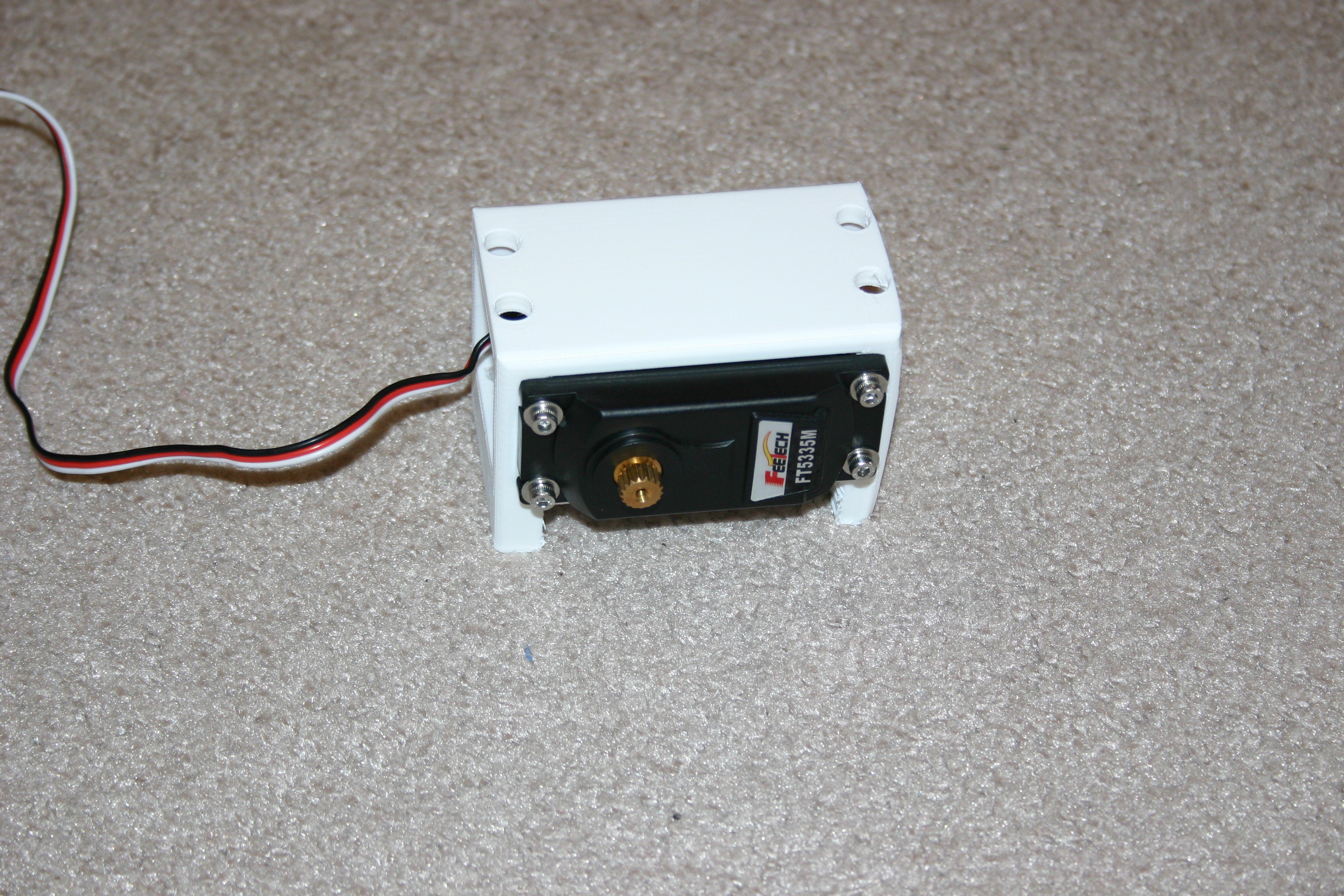
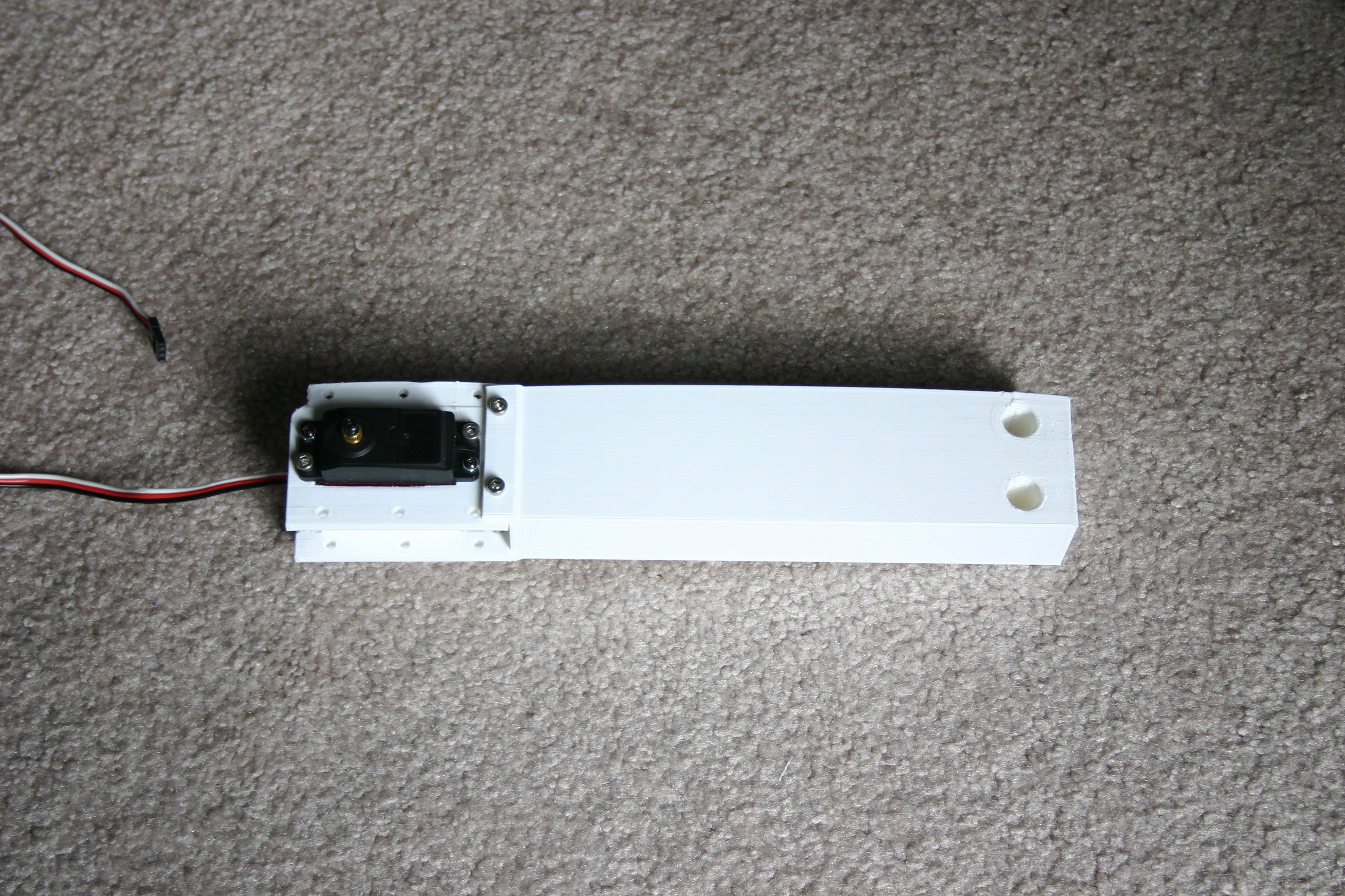
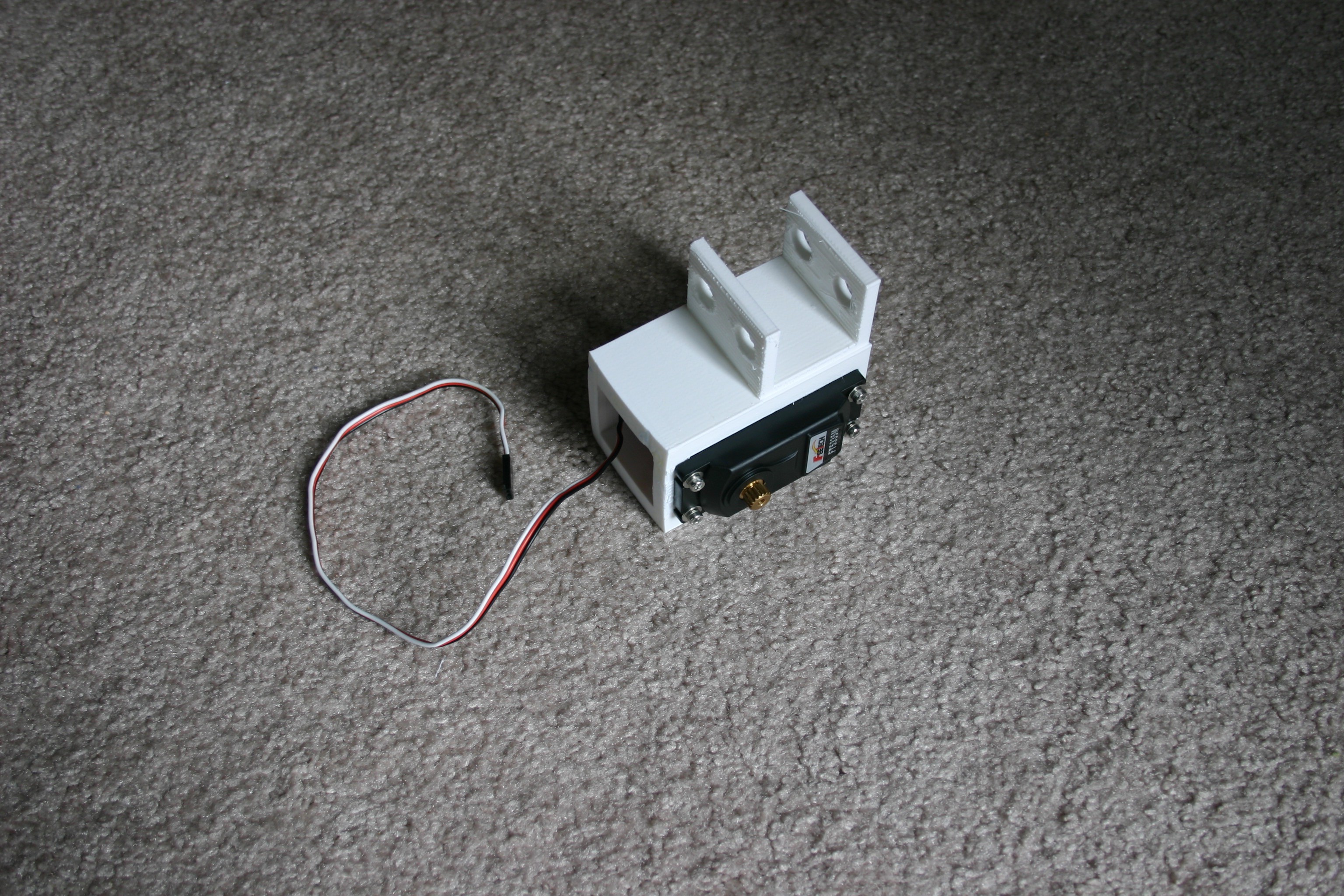
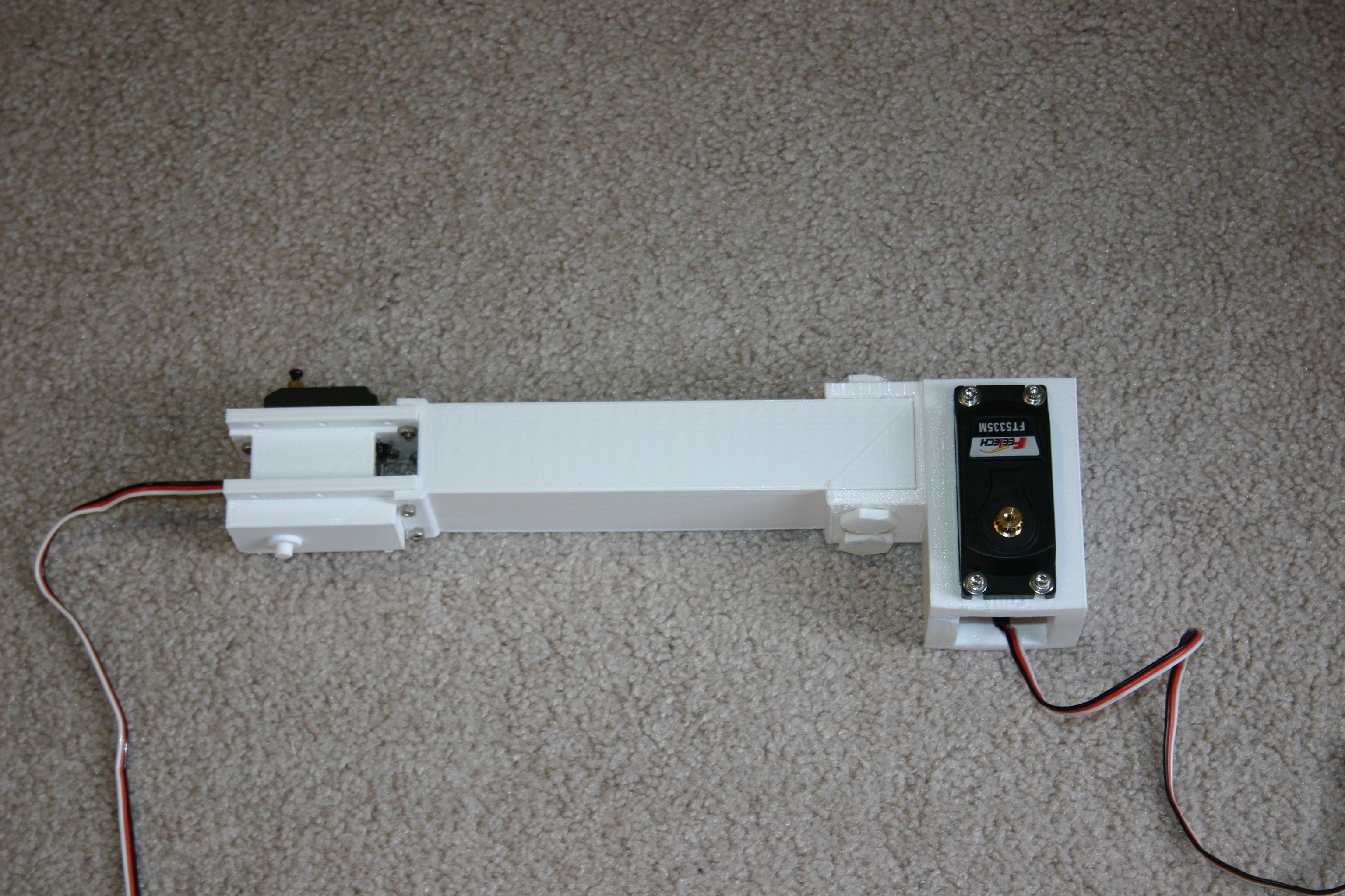
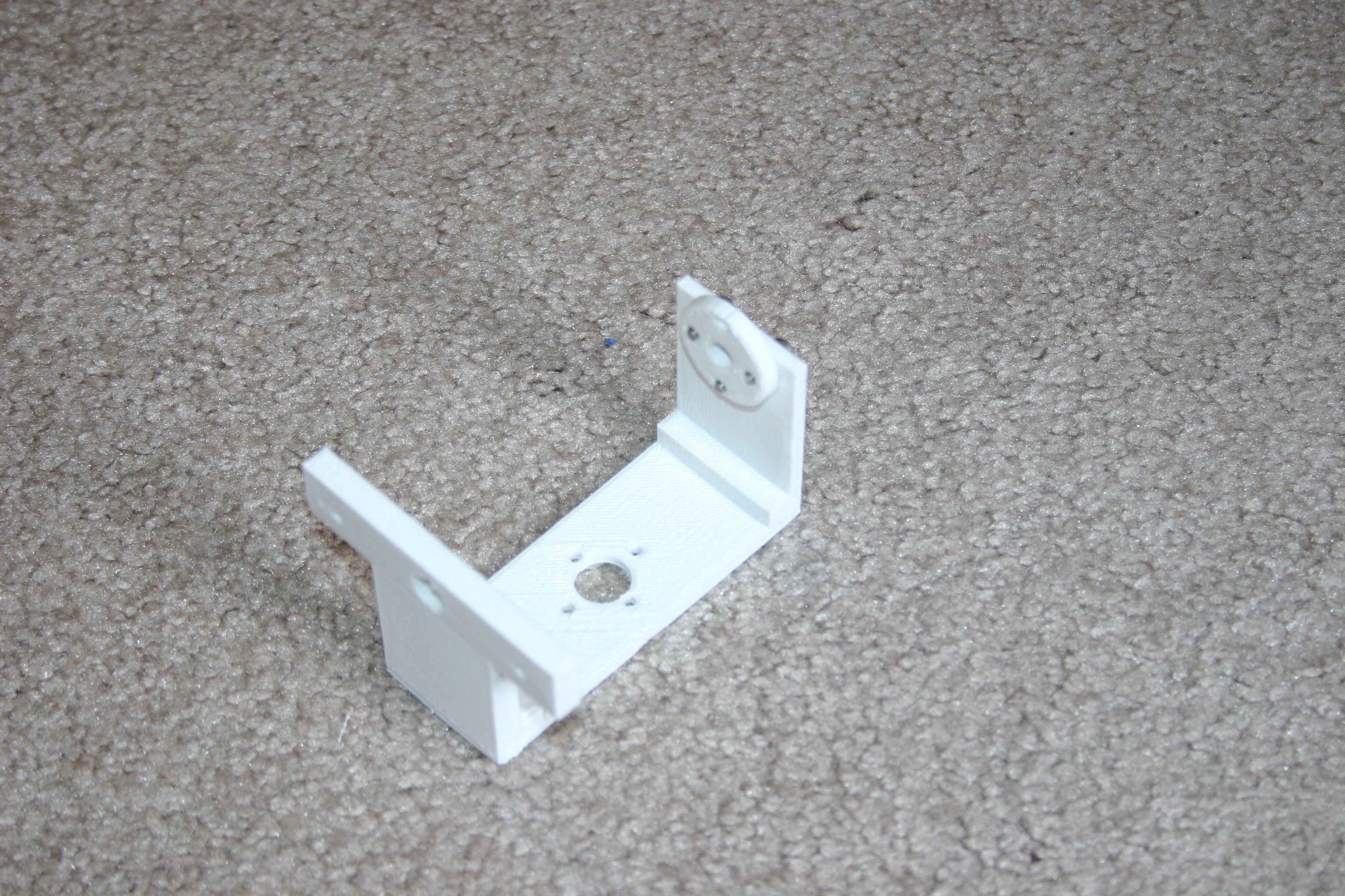
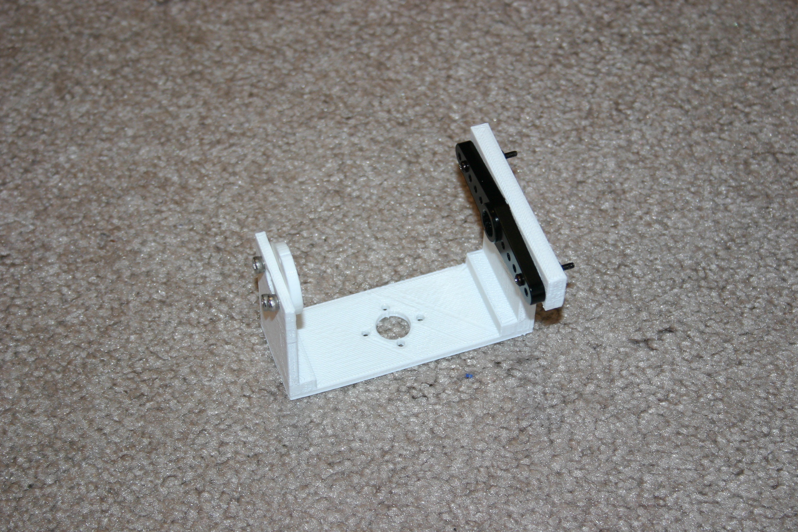
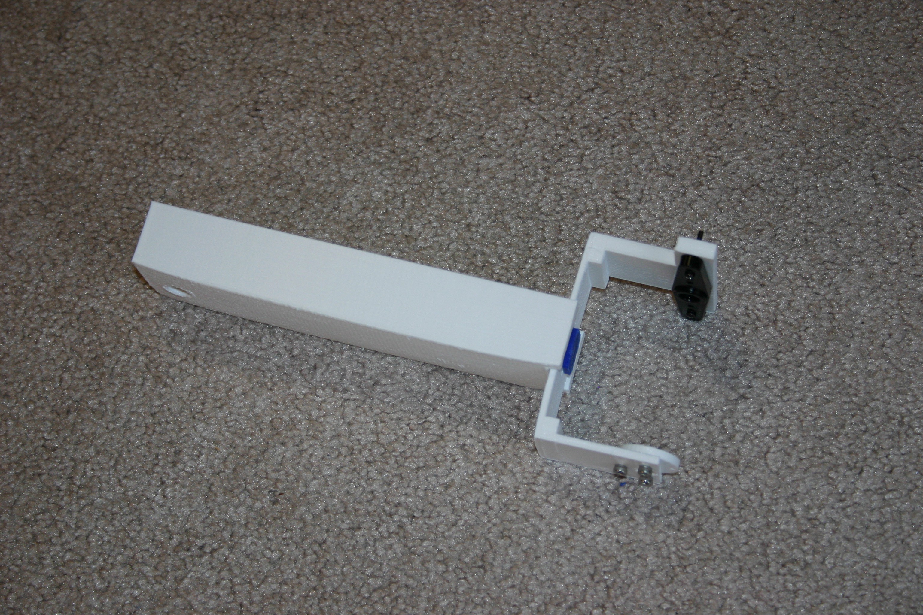
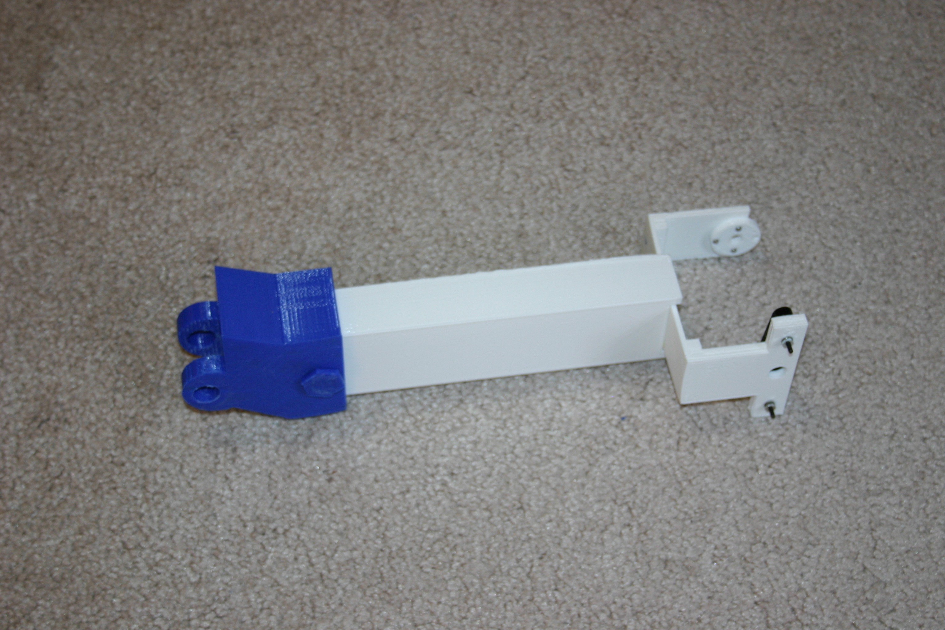
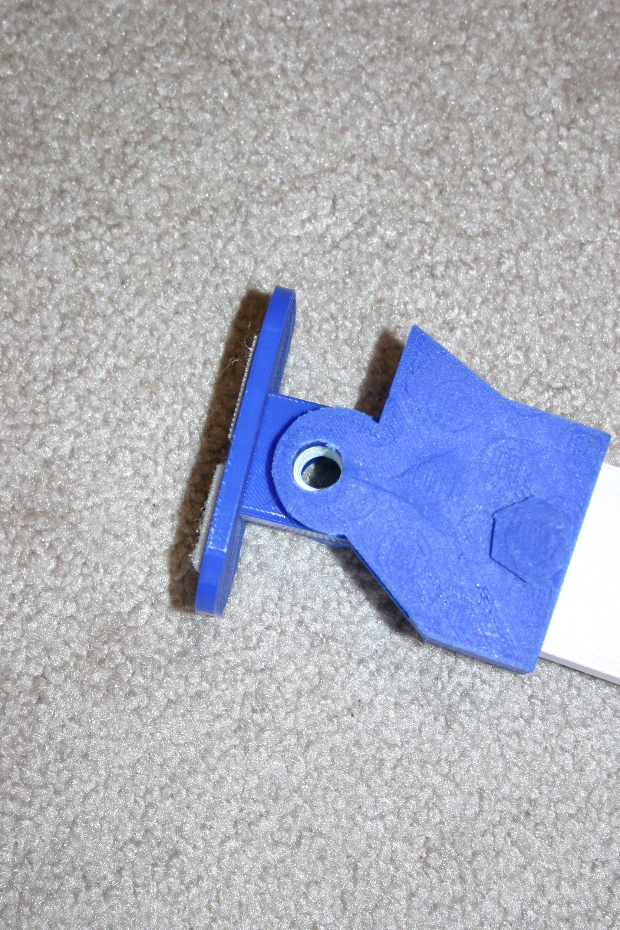
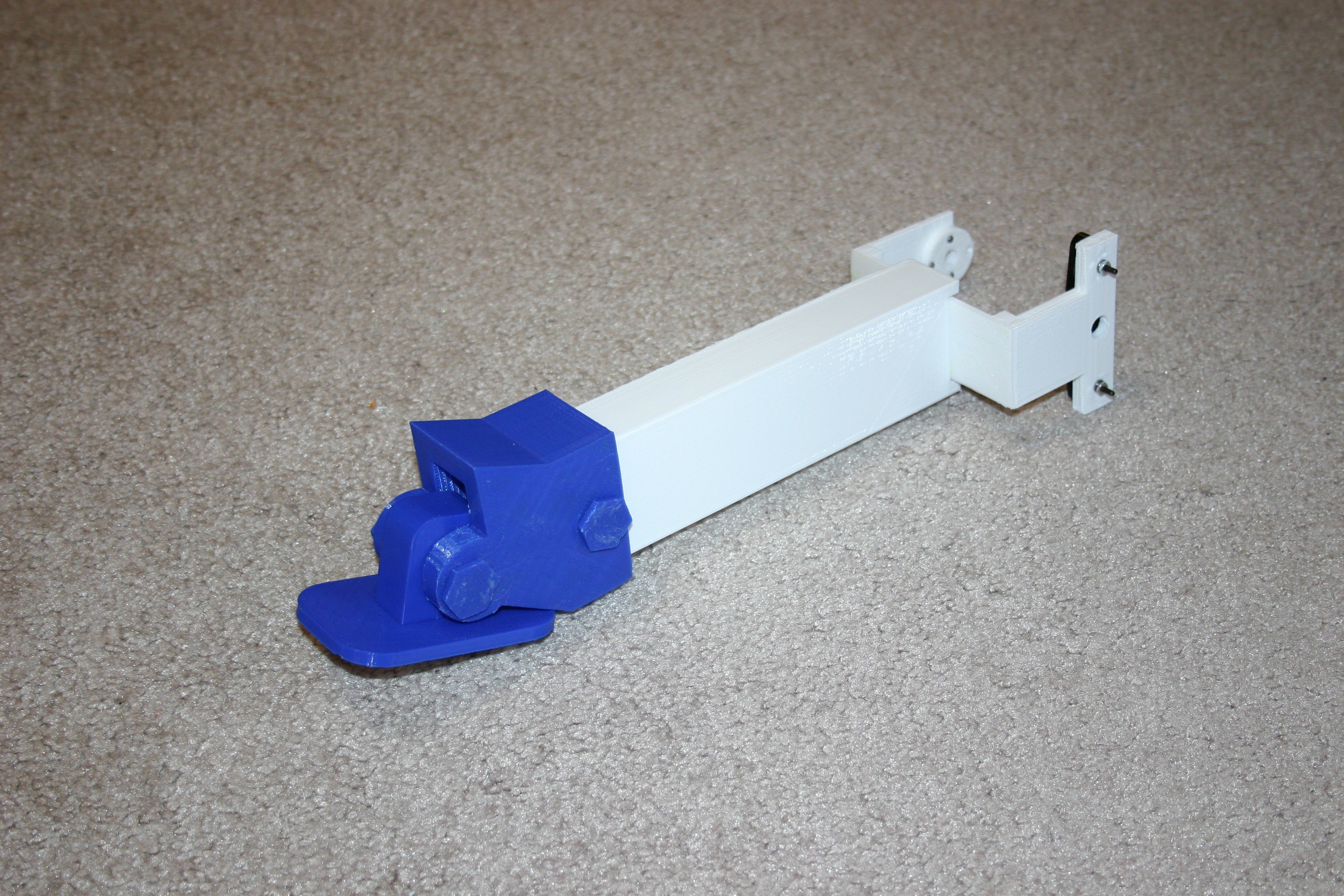
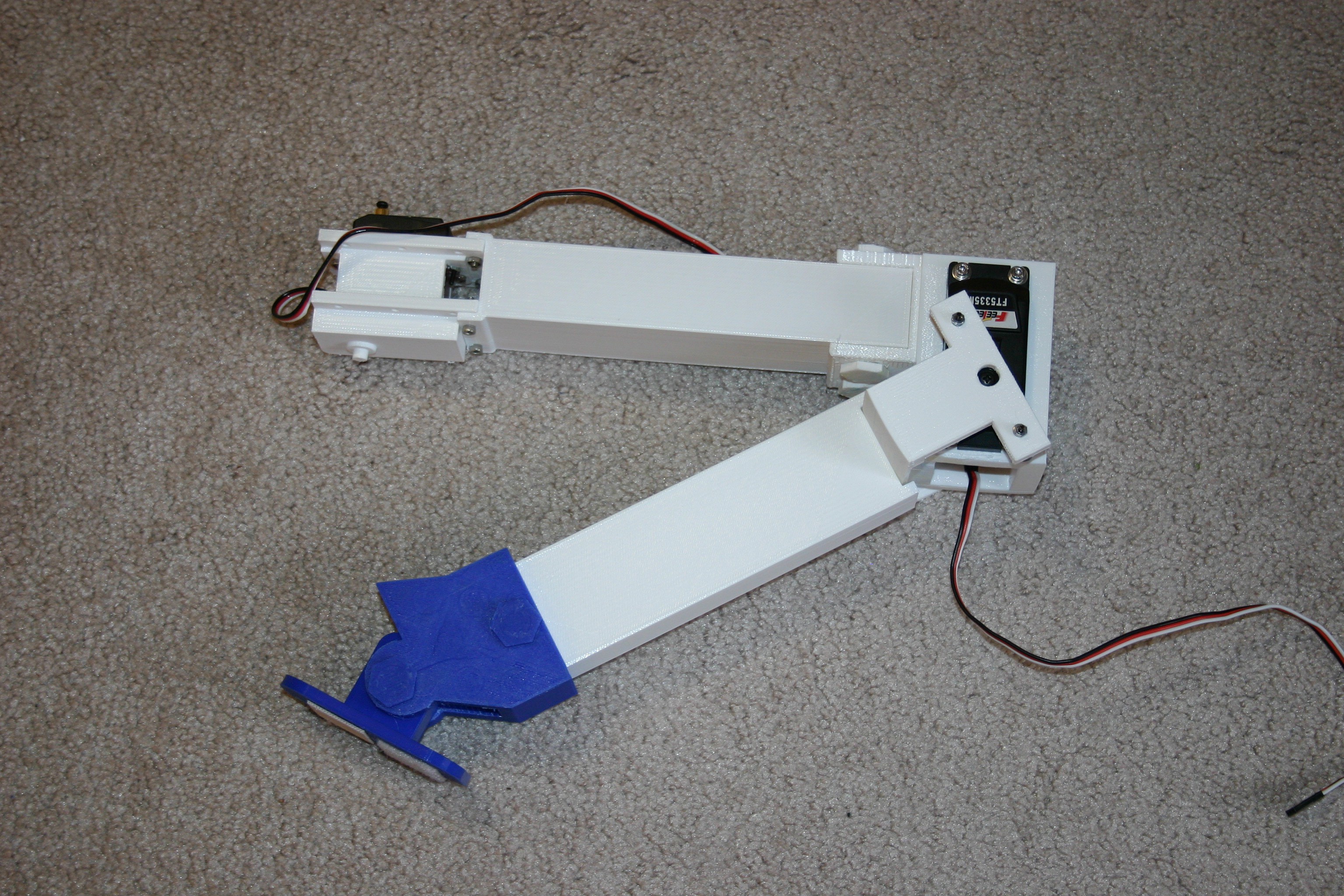
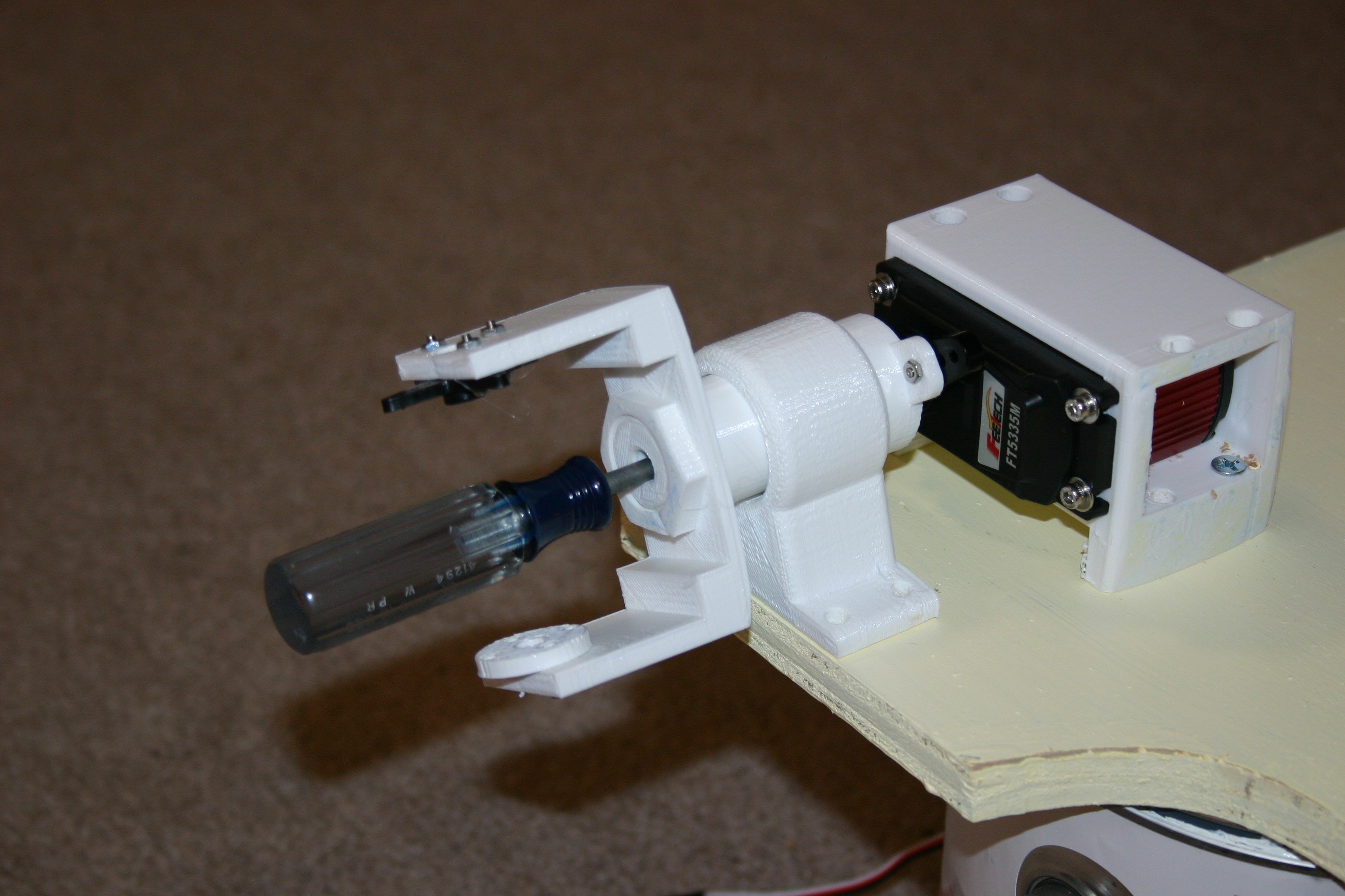
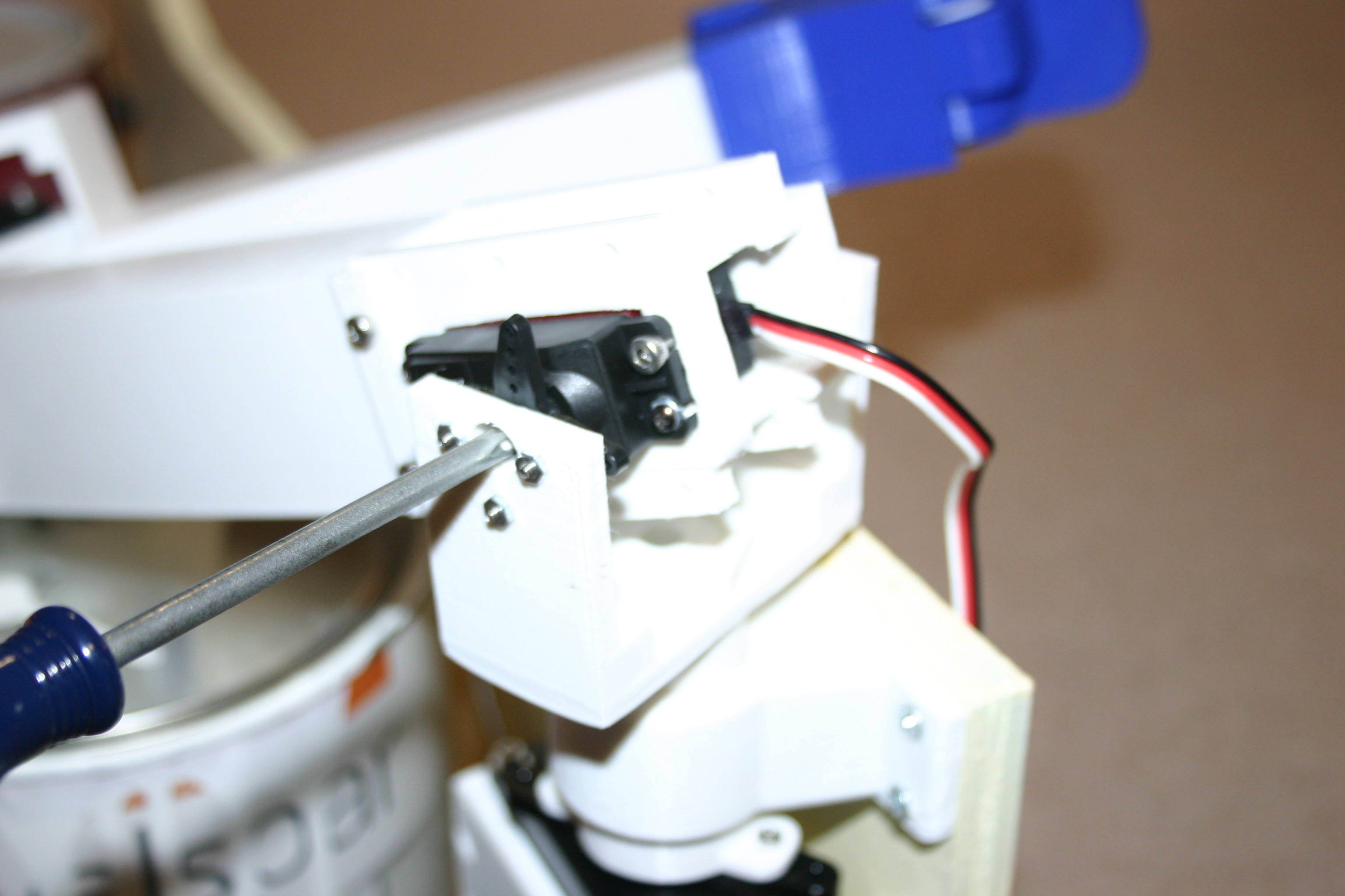
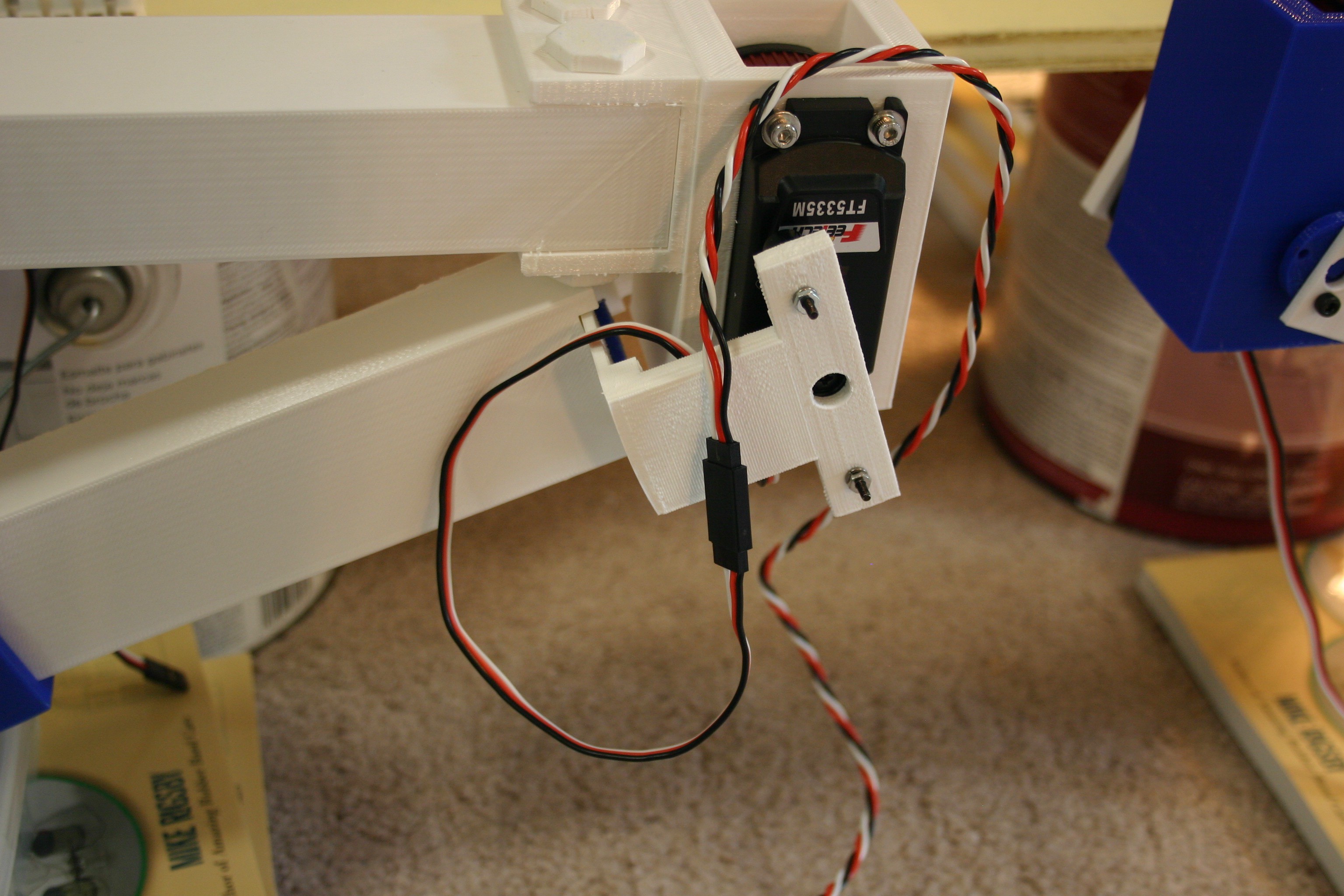
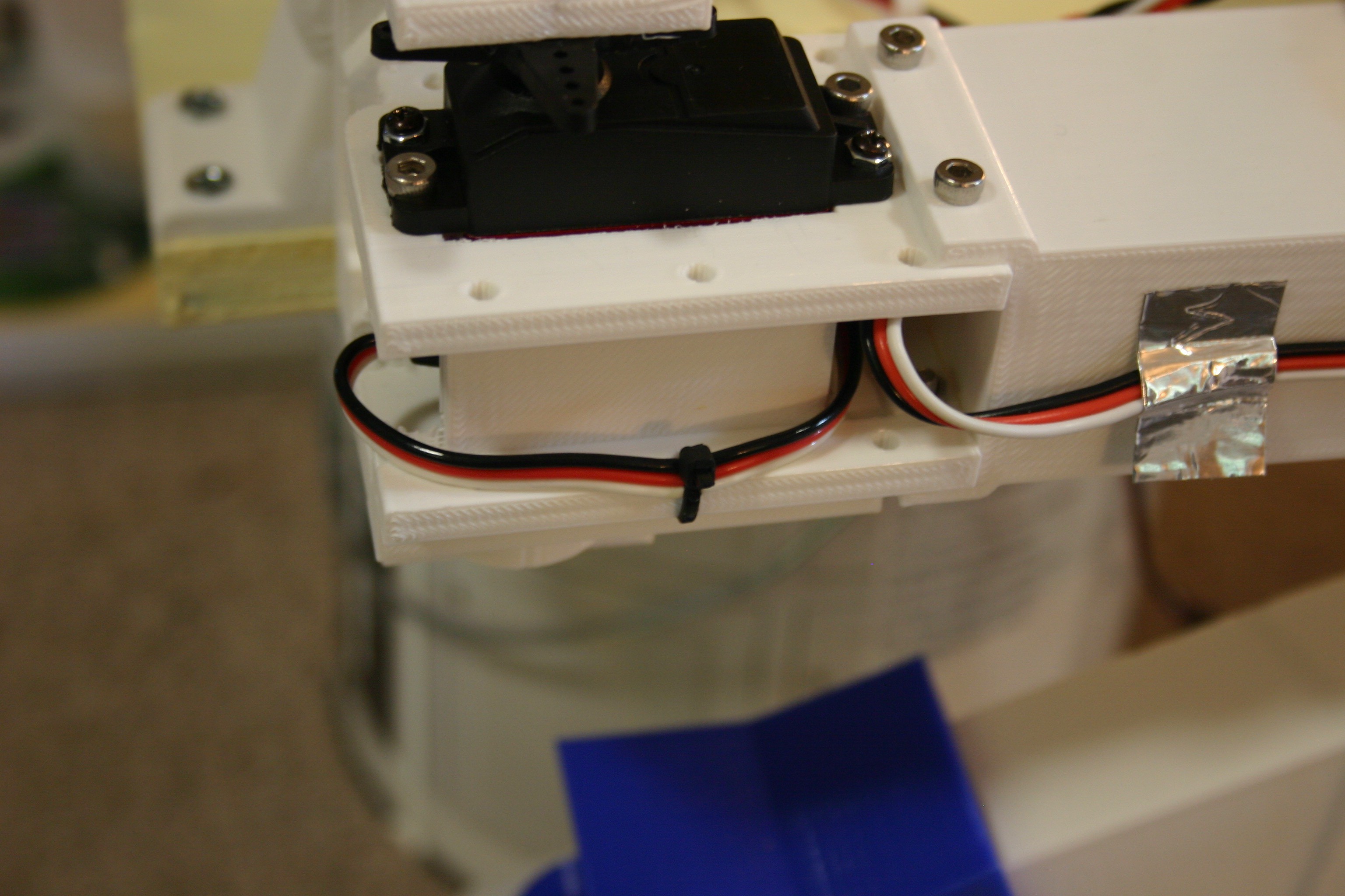
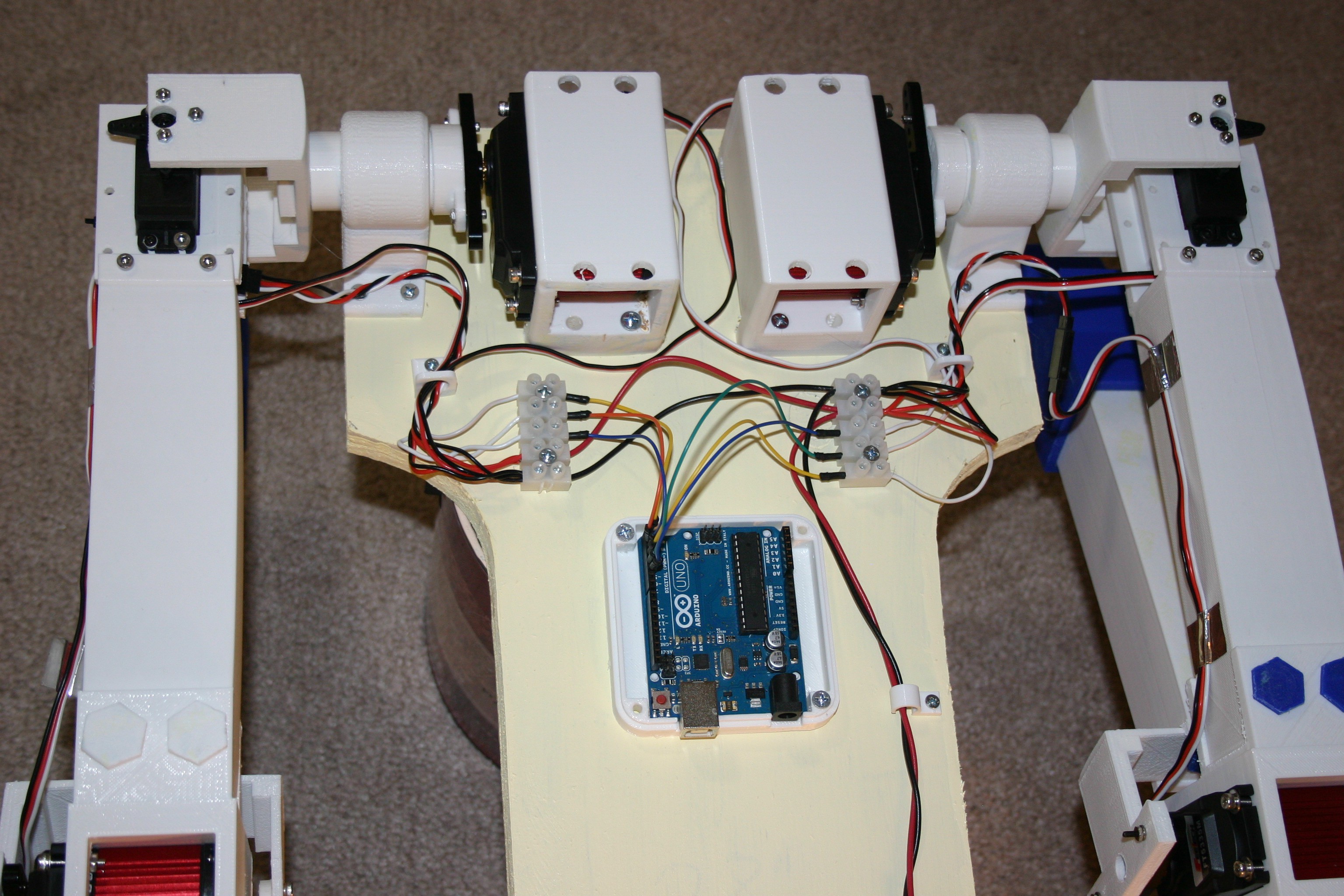
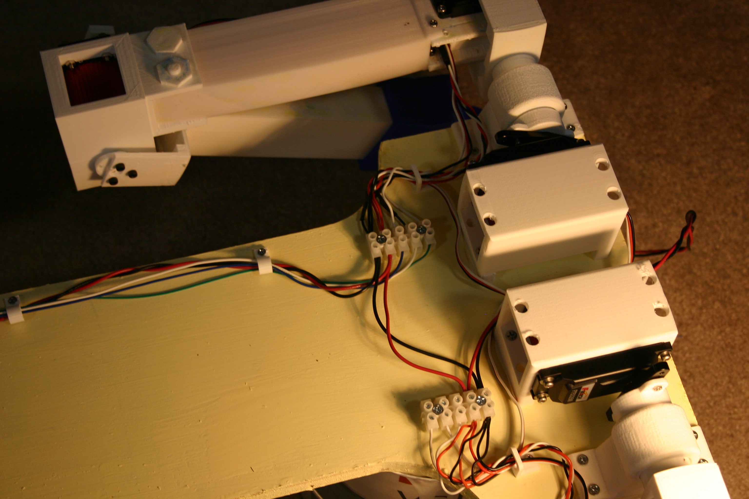
My first "shoulder connection" put all the "up/down" and "rotate" stress on the servo motor.

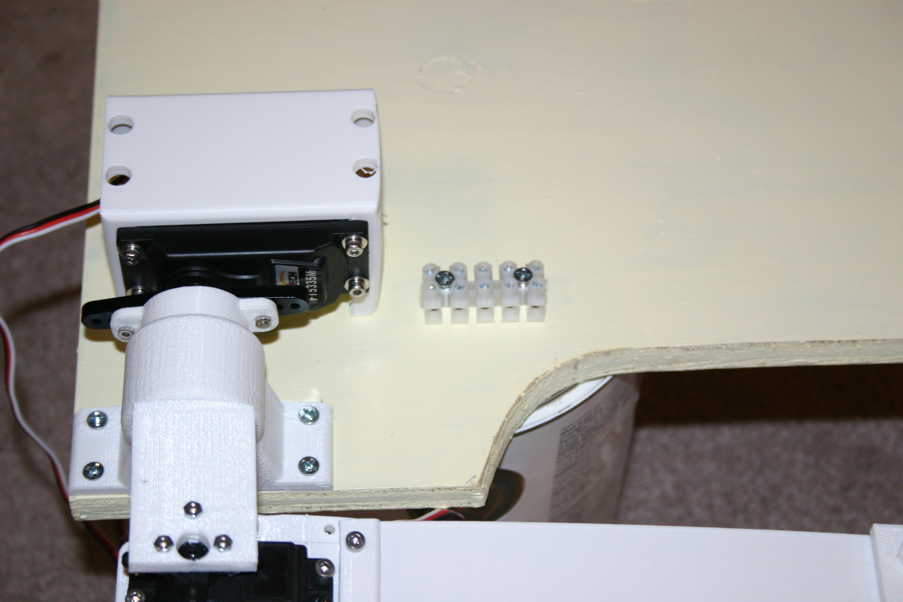
This looked like a bad idea, so I created a bearing block and heavy shaft to absorb the "up/down" load and let the servo motor's gearing handle the rotation only.

The bearings are snowmobile bearings available on Amazon.
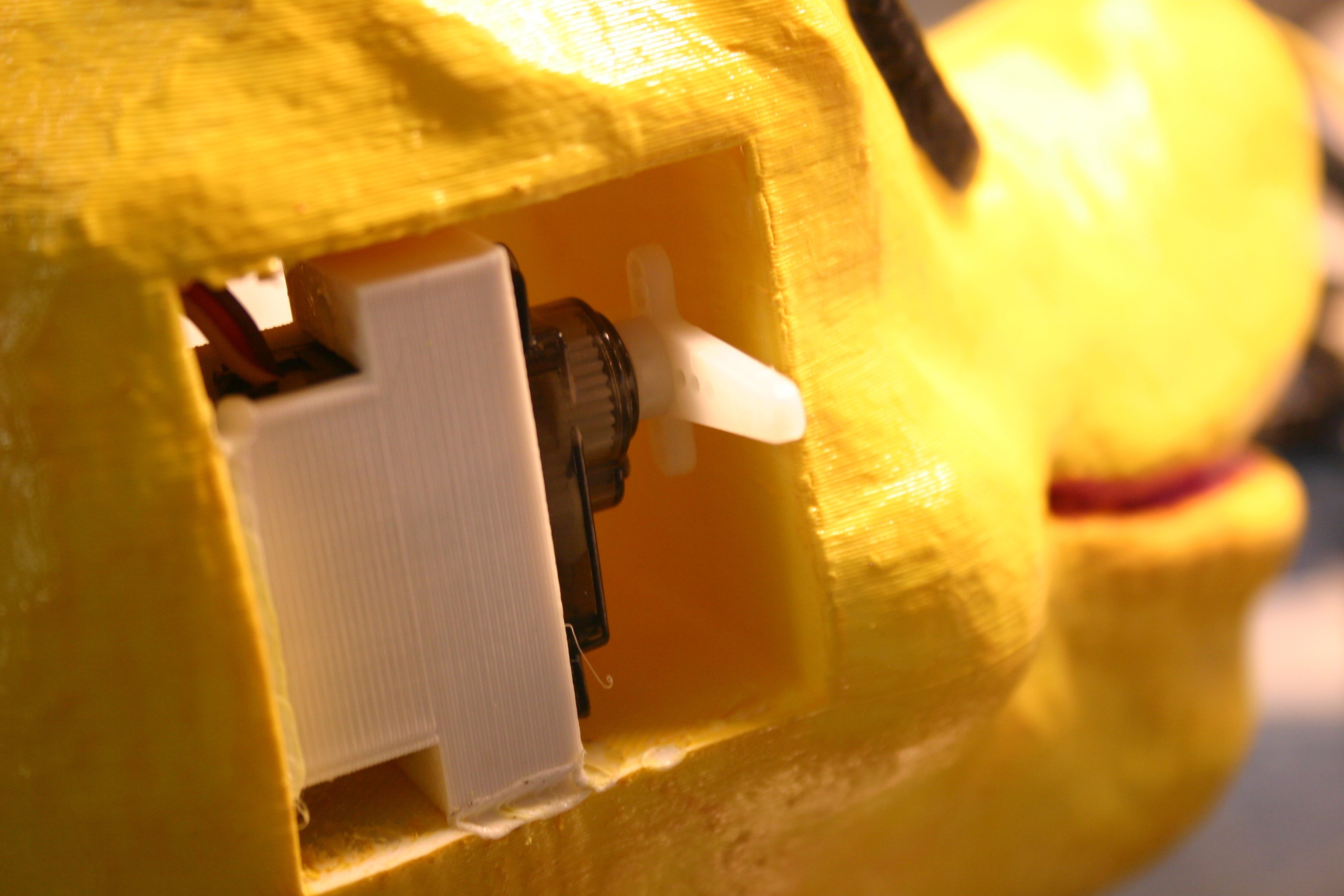
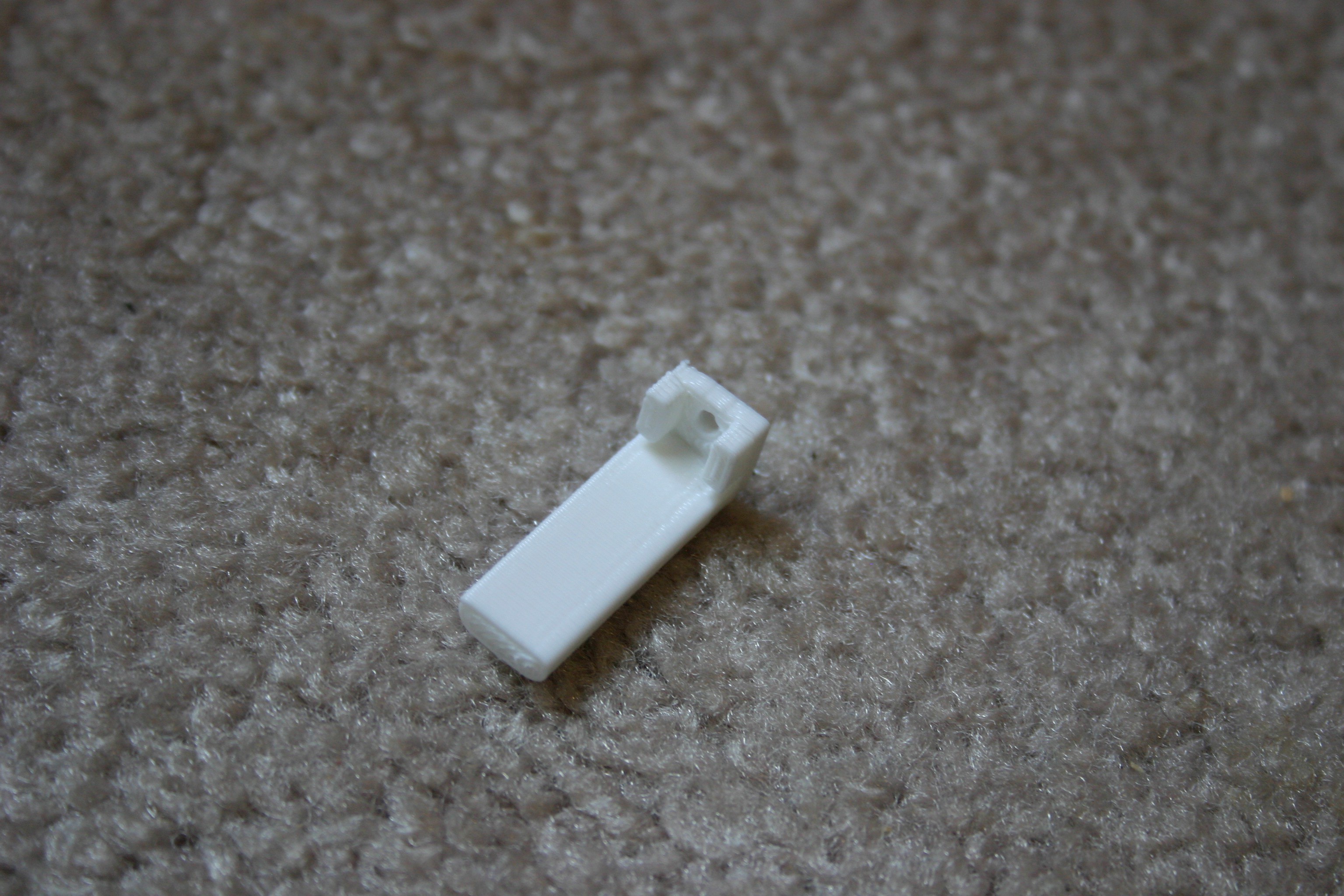
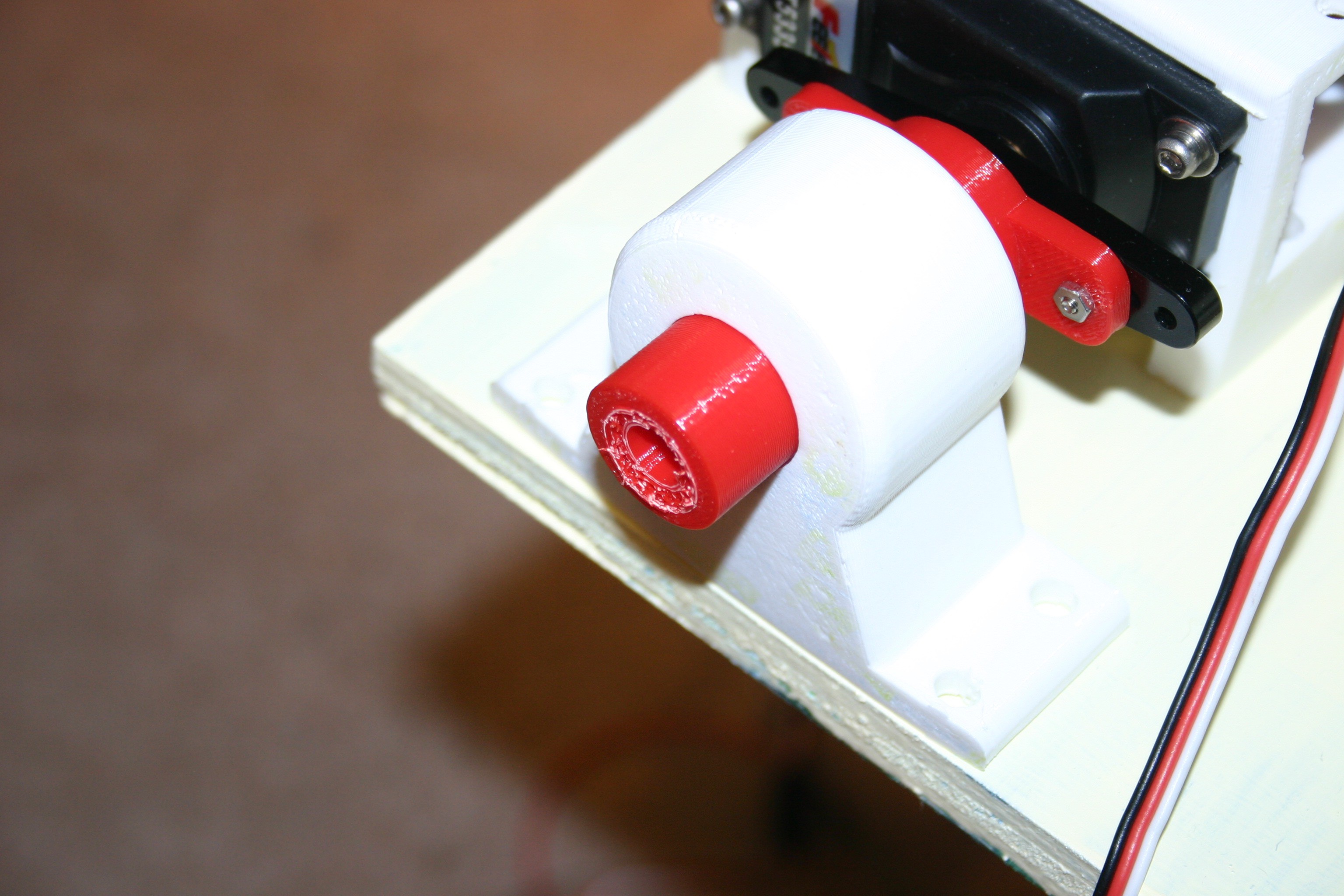
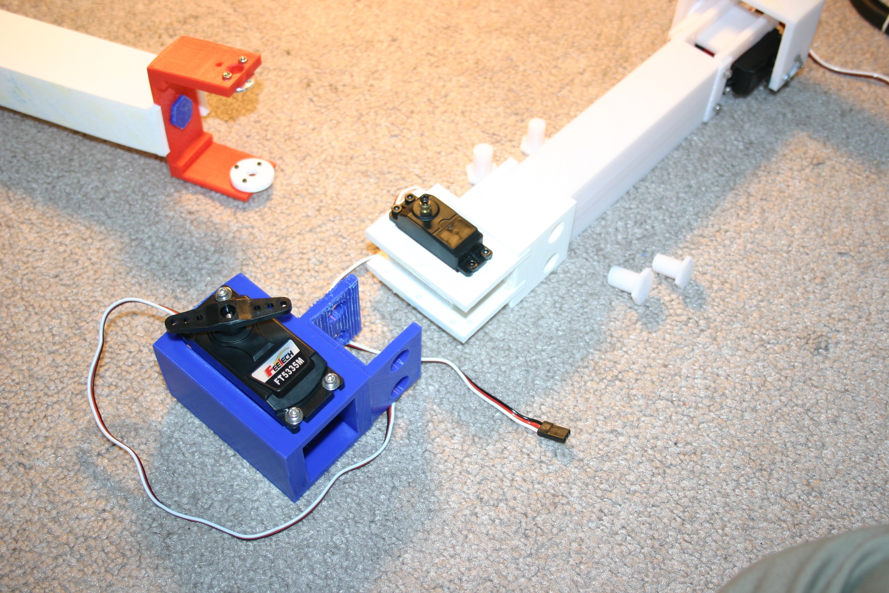
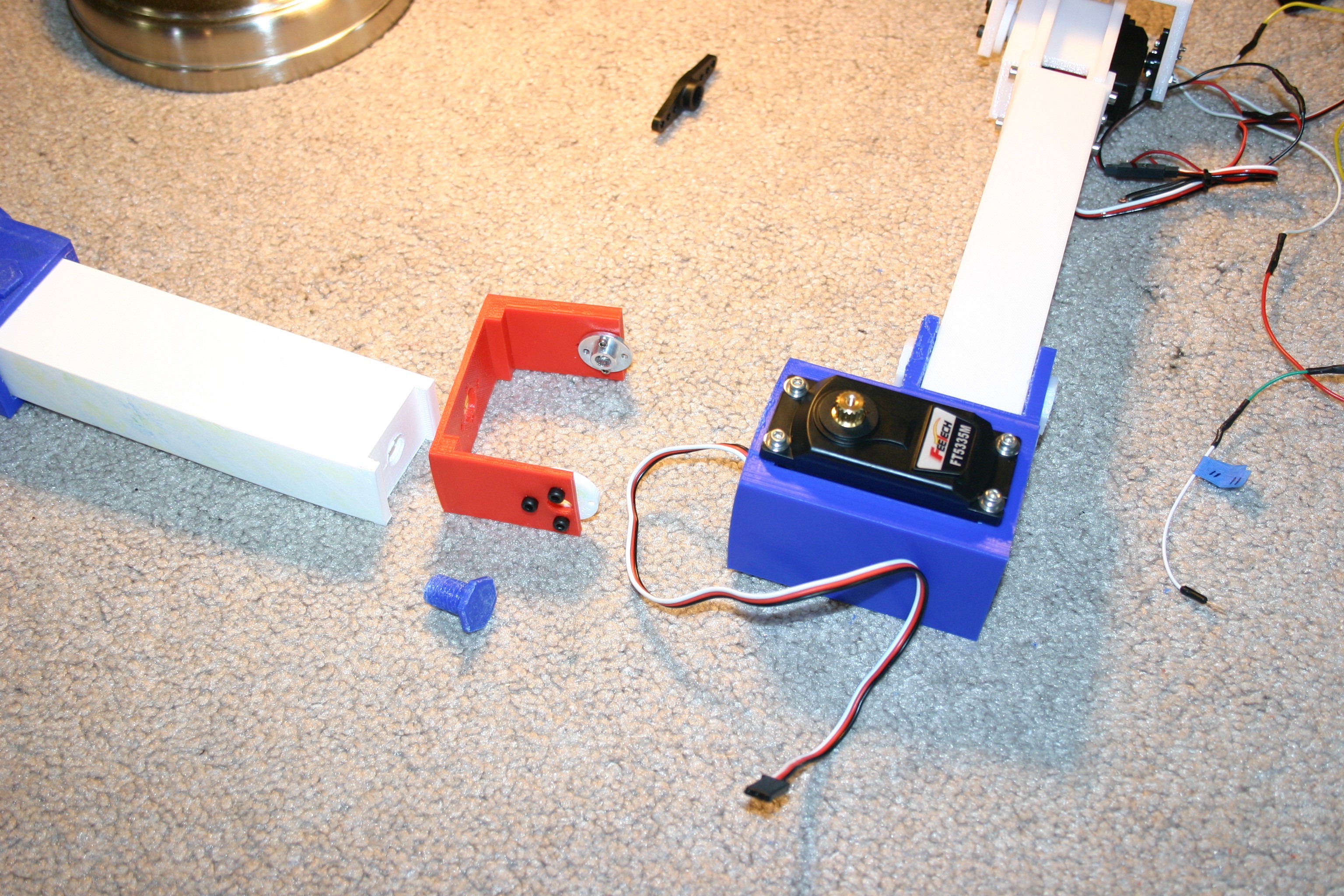
I designed the servo motor mounts such that there is a sort of "back bearing" opposite the shaft so that it is easier to attach moving limbs.

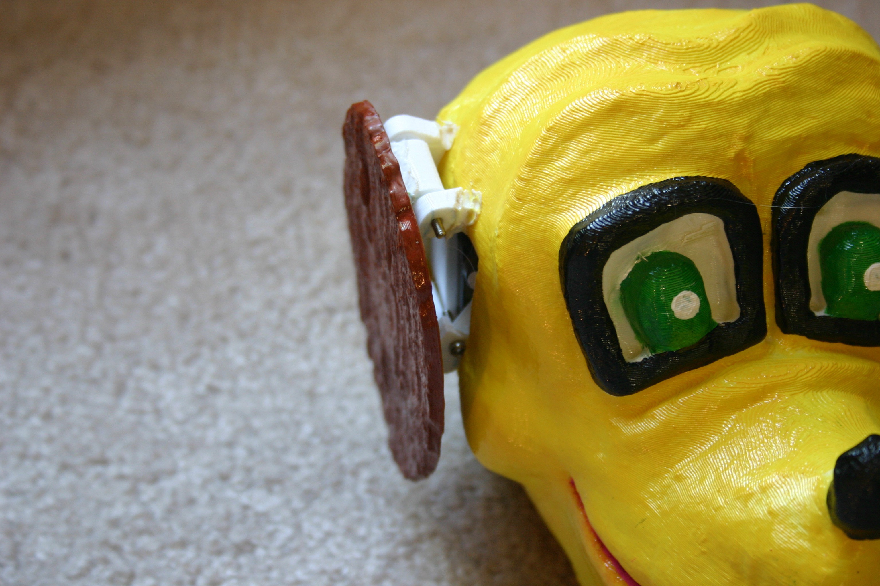
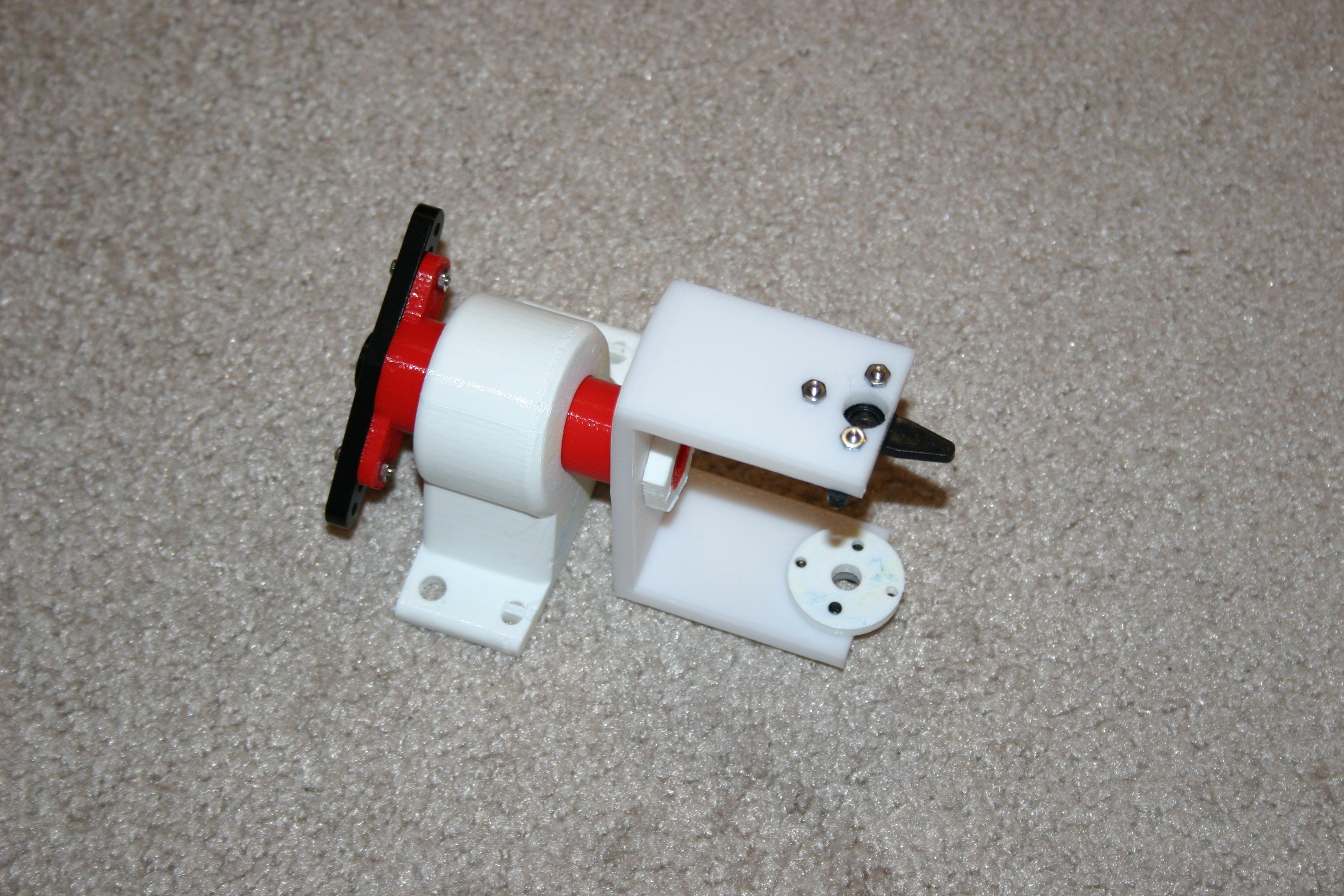
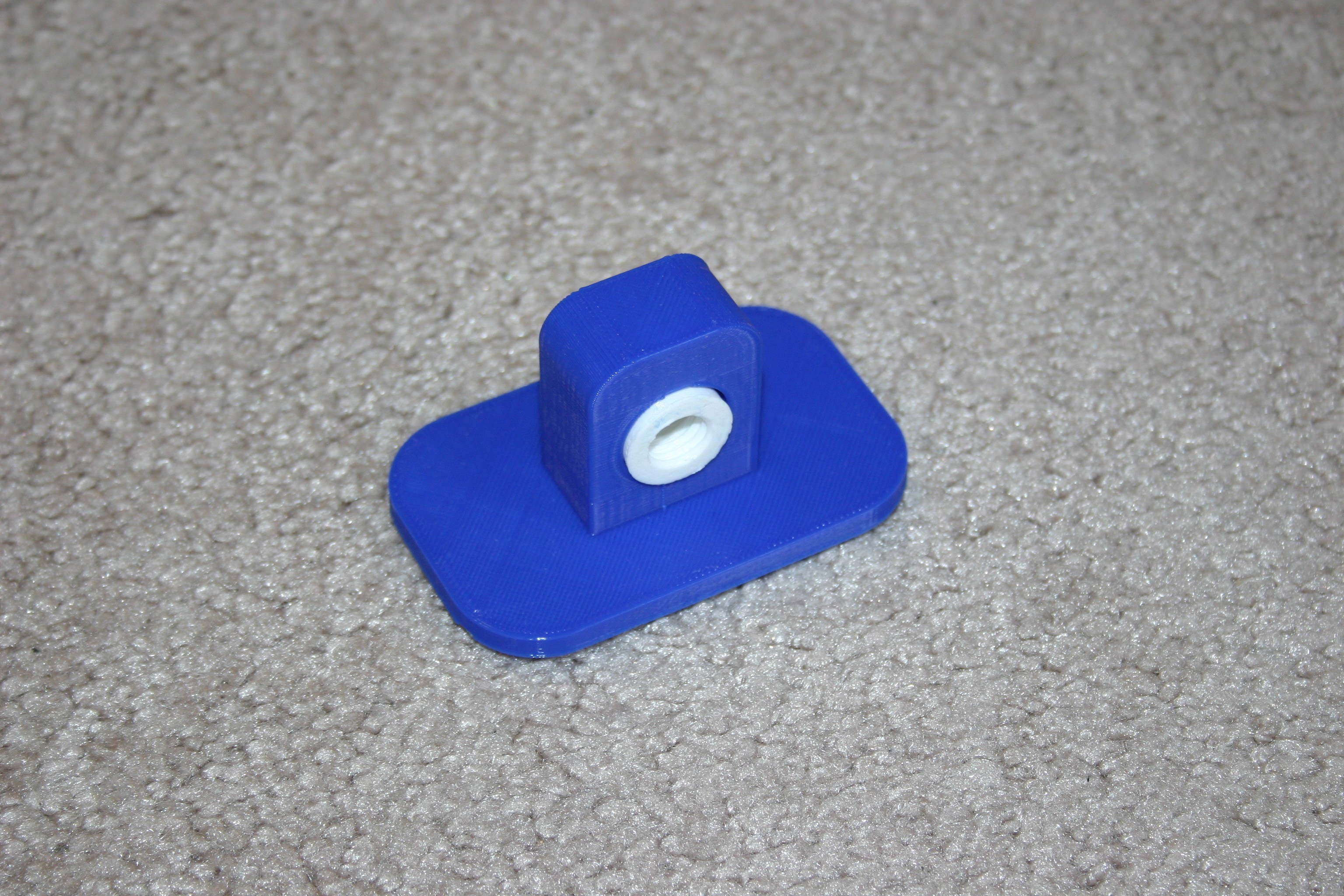
The first foot was a wheel--but that rolled all over the place, so I created a movable flat pad for better traction.

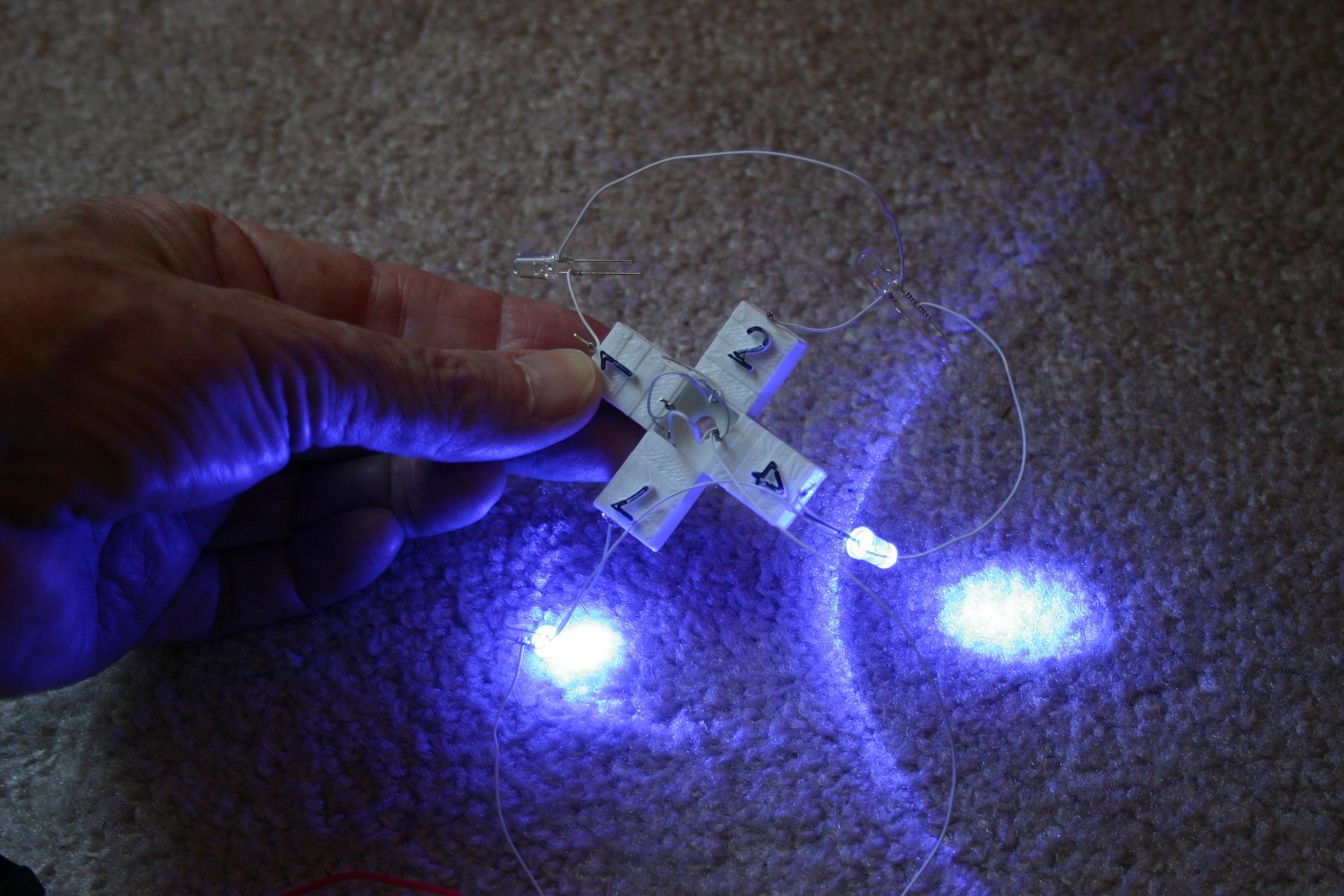
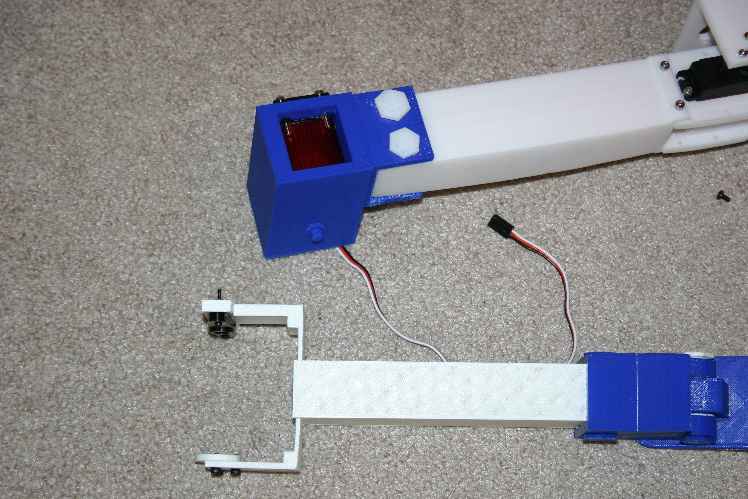
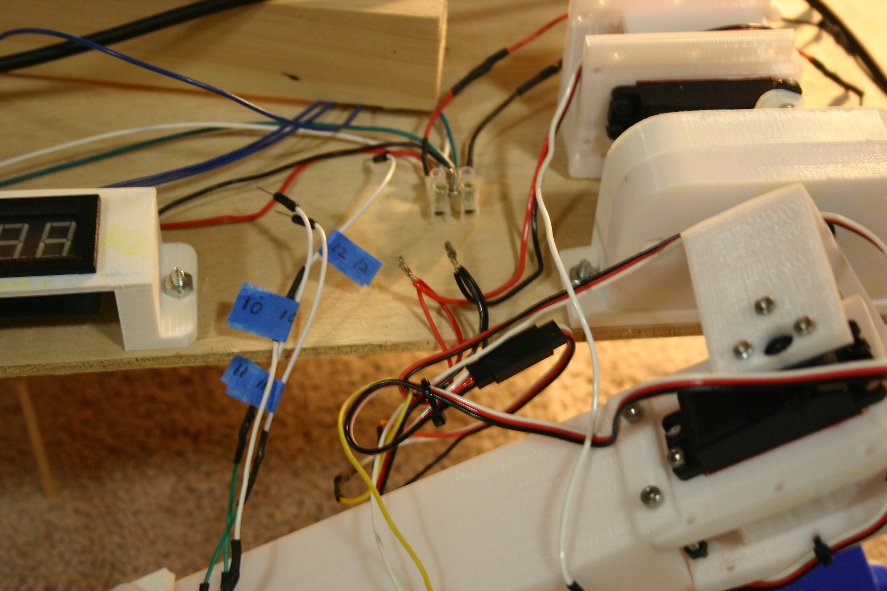
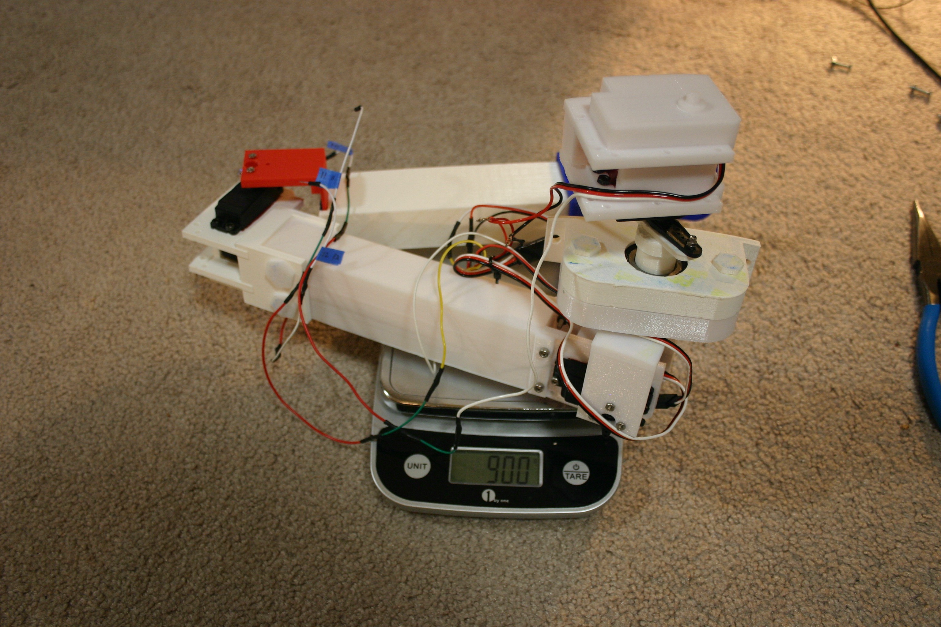
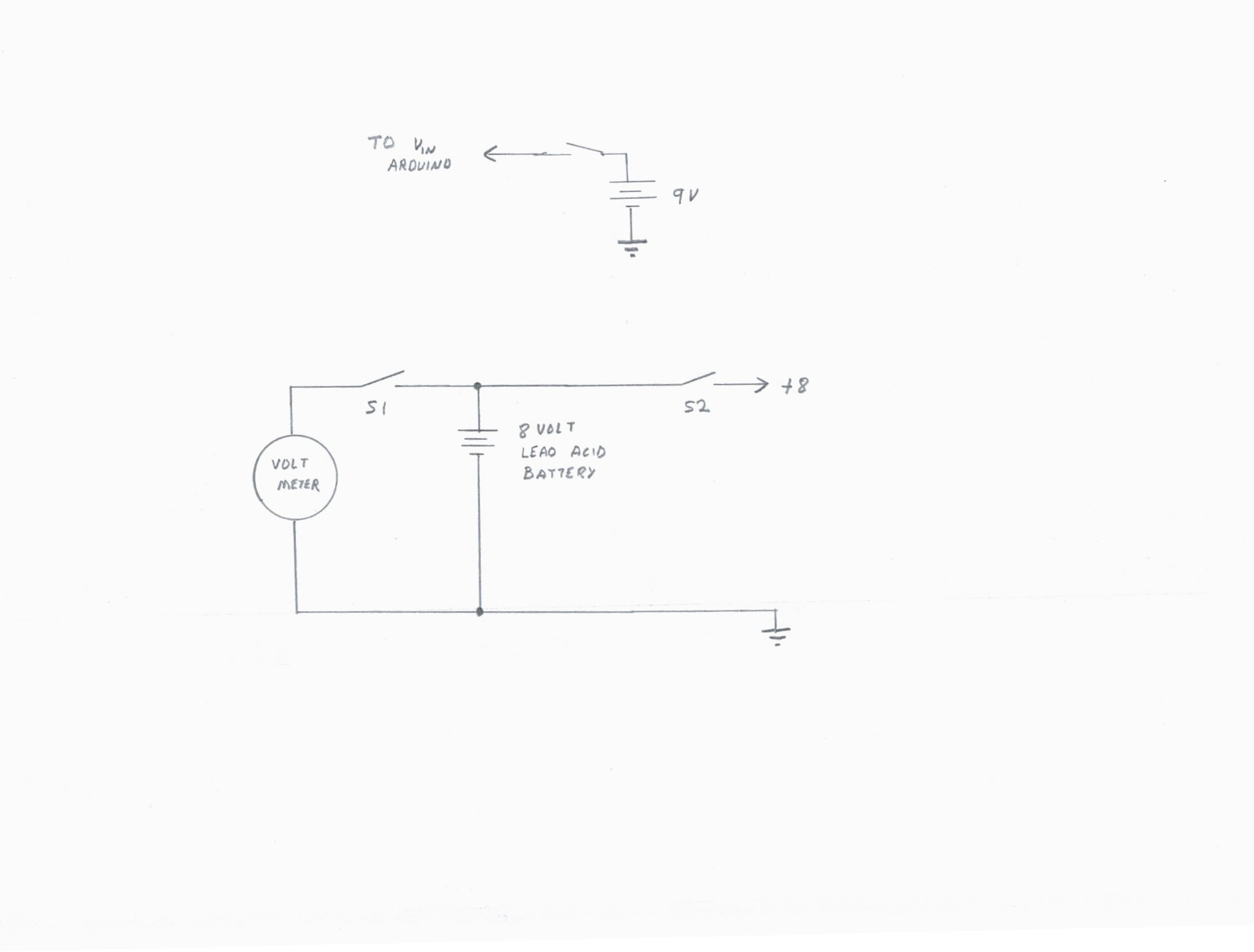
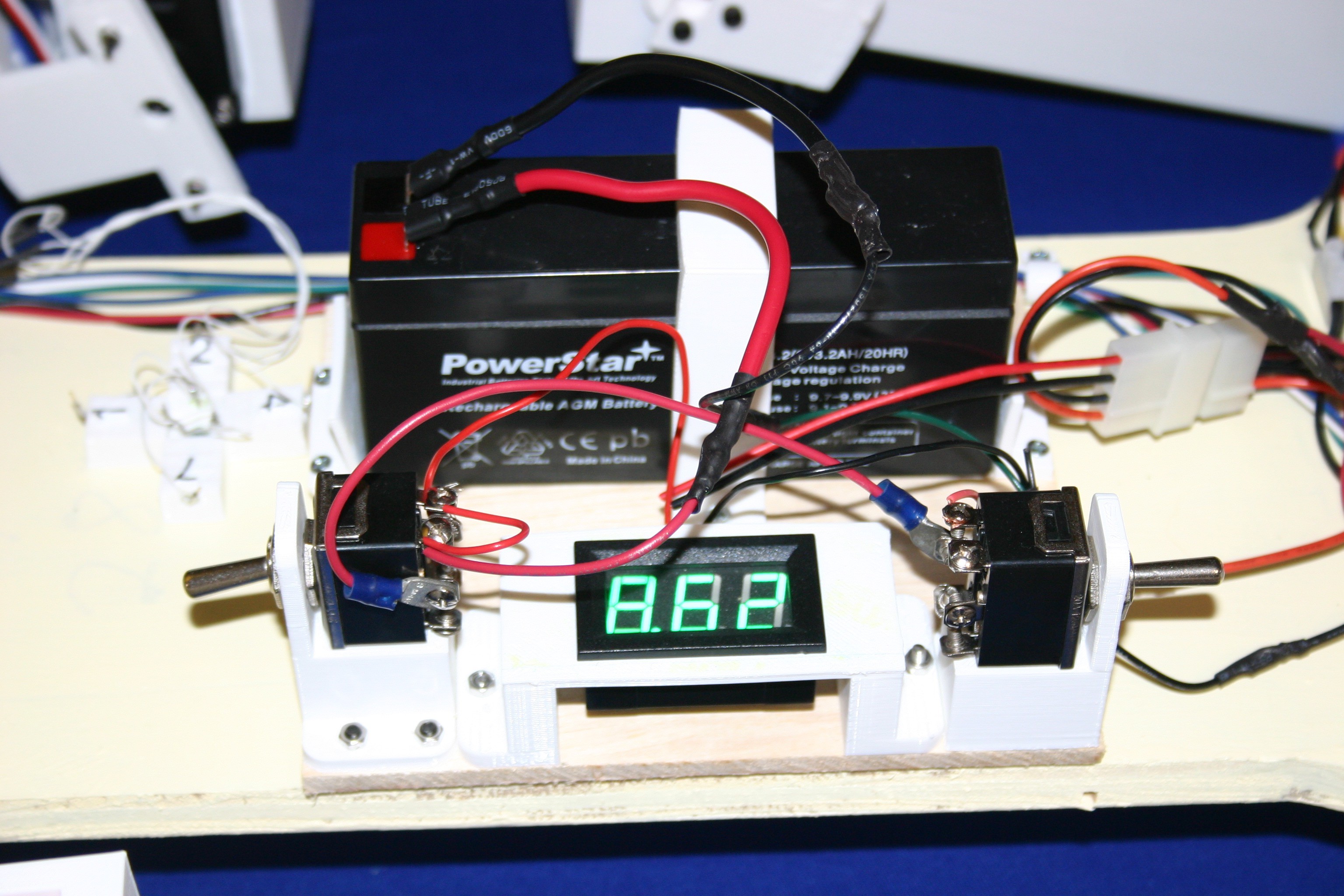
I mounted a digital voltmeter up on the body--just to keep track of what was available for the servo motors.

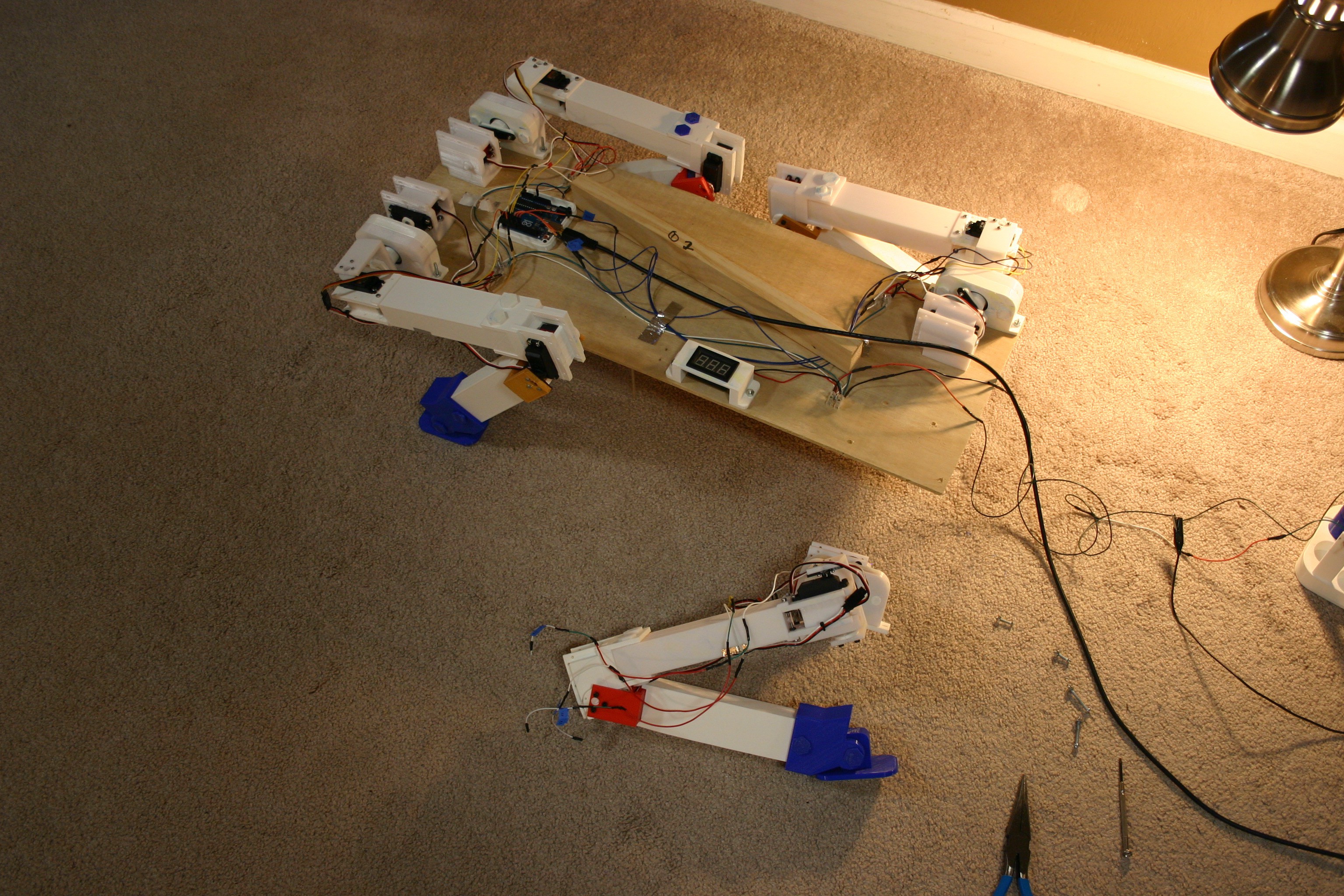
So, there's a long way to go, but this walkable platform (when it works) will be useful for robotics on smooth or rough terrain.

On February 27, the first attempt at standing was made....
Read more »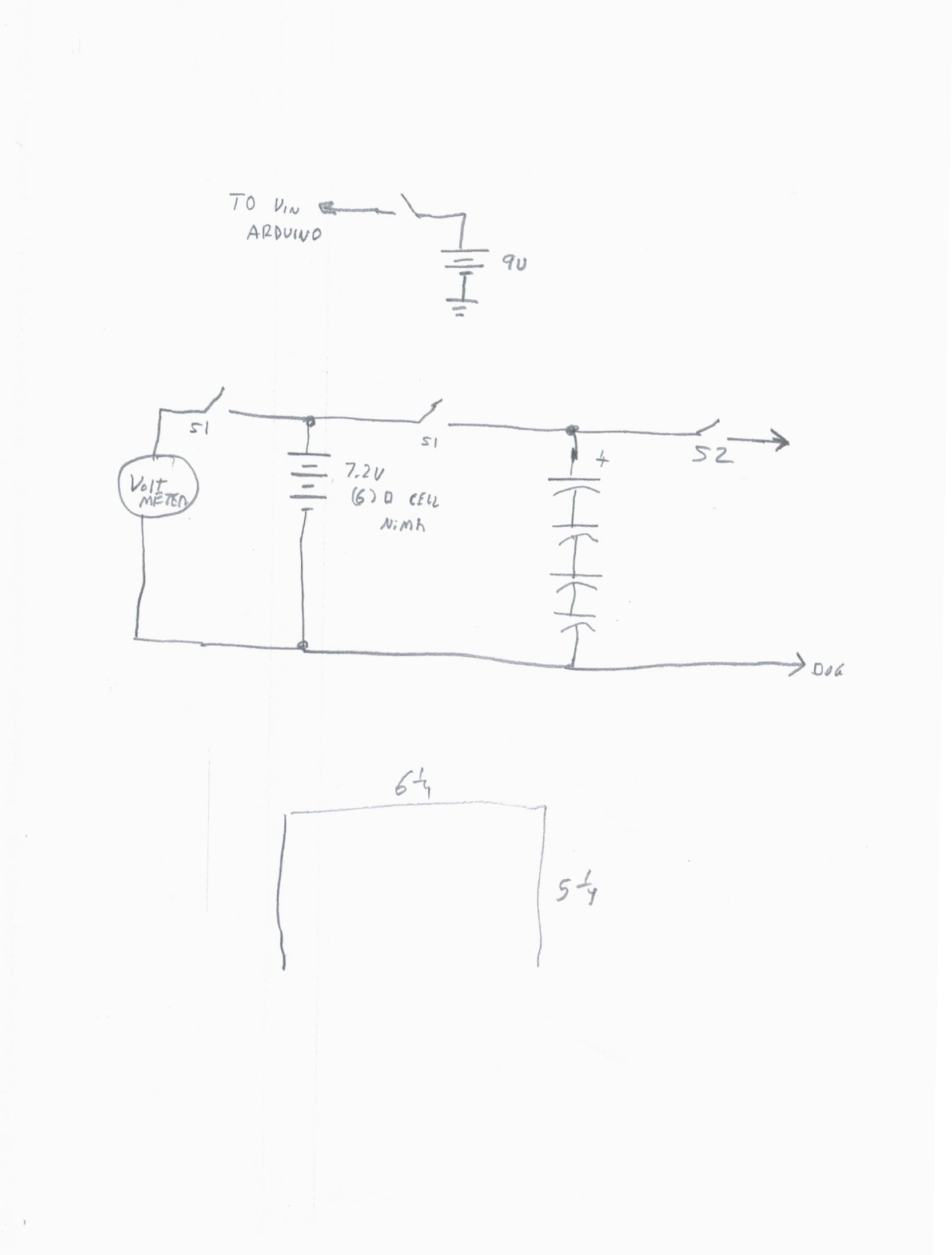


 Aaed Musa
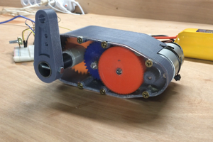
 Brian Brocken
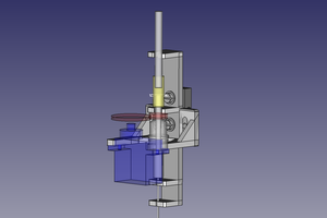
 Michael Mayer
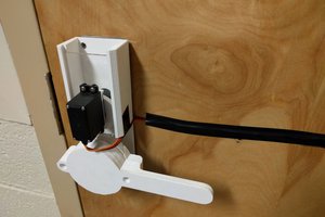
 Keavon Chambers
Have you seen: https://hackaday.io/project/157812-3d-printed-robot-actuator? He has a system that trades motor speed for torque, all 3d printed (except the motors). It might help? His intention is to make something that can jump, via pure motor/actuator force. Most biological systems that jump (well), involve a spring-loaded joint that gets "instantly" released to generate much more force than the available muscles could. In humans, etc, that spring force comes from the "stretch" or "spring" which loaded tendons have. But for "instant" application of large force, springs work pretty well. Not sure if that would make things too complex for your system, though.