Reverse engineering a Life Optics M5/Leica HM500
My attempt to get a Life Optics M5 (aka Leica HM500) head mounted microscope/varioscope running.
My attempt to get a Life Optics M5 (aka Leica HM500) head mounted microscope/varioscope running.
To make the experience fit your profile, pick a username and tell us what interests you.
We found and based on your interests.
Previously I discovered what looked like a TTL level serial output using the oscilloscope. I have since connected this output to a PC via an FTDI TTL-232R-5V USB to serial cable. I then ran RealTerm and configured the serial port for 9600bps 8-N-1. On powering up the varioscope we are greeted with the following.
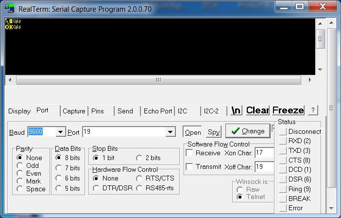 It speaks! Even if it doesn't have much to say. This is good news and quite encouraging. It looks like the M5 is powering up correctly and communicating at least. The yellow wire is clearly a serial output.
The next step was to see if either the white or brown wire is a serial input to the M5. I first connected the white wire to the serial output from the PC. Unfortunately, sending random characters or command like "zoom" didn't elicit any response from the M5. There are no acknowledgements or error messages. This does not necessarily indicate that it's not a serial input. I may also indicate that it does not understand what is being sent and is ignoring the input. Without any protocol information it is difficult to know.
Connecting up the brown wire was more interesting. Every time a character is sent the M5 responds with a sequence of "0" and "$" characters. For example sending a lower case "a" causes the device to respond with "000$" while sending "x" results in "00$". Receiving a multiple character response to a single character input is quite cryptic and it leads me to believe that this is not a serial input but an input for some other form of encoded data from the control box. Perhaps something that represents the state of the switches and controls on the control box.
I decided to hook up a function generator to this input to see the effect of signals at various frequency and duty cycle settings.
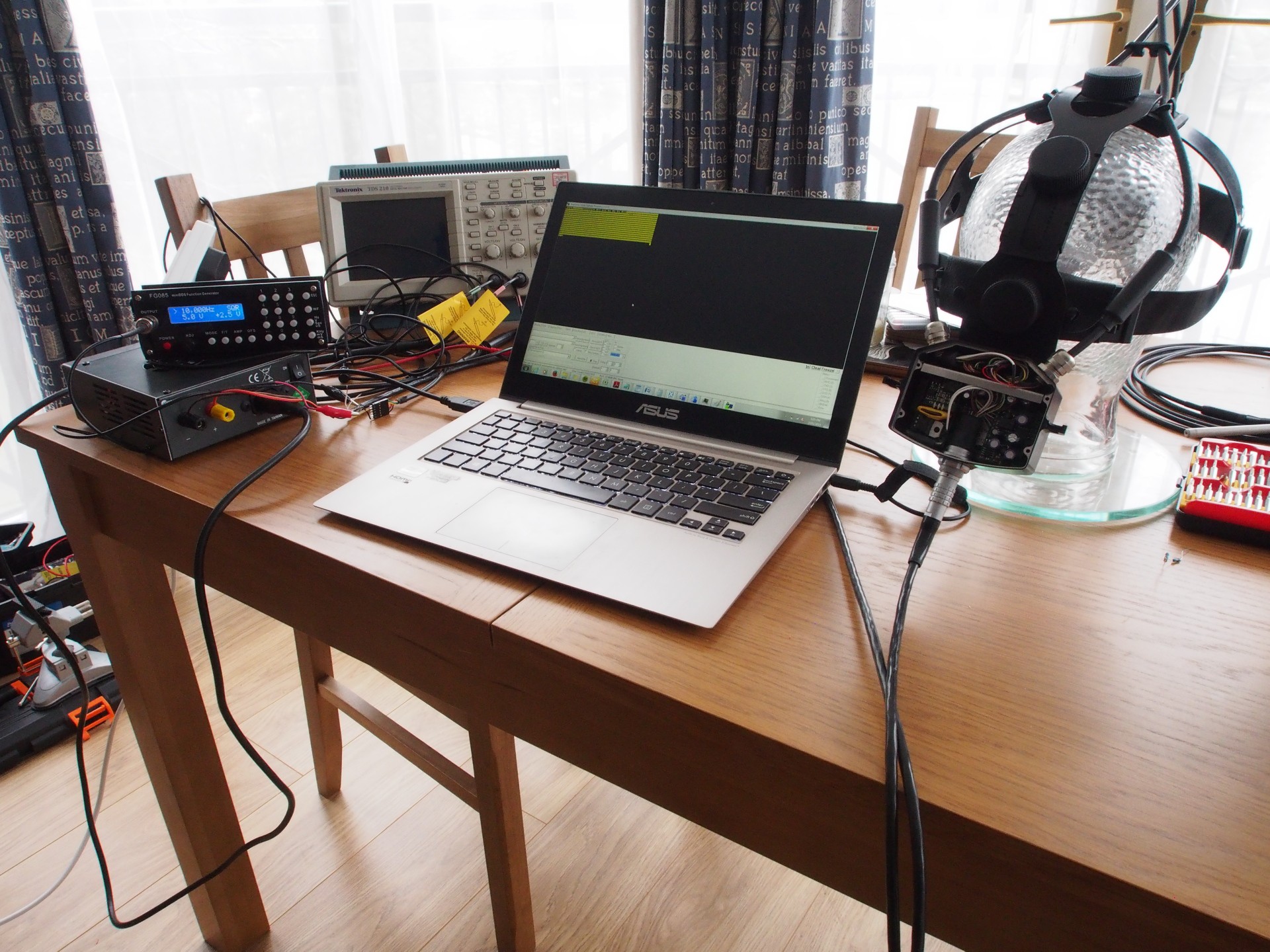
Feeding in a square wave at most frequencies between 1KHz and 10Khz seems to produce a long string of "0" characters from the serial output. Once the square wave is stopped the M5 sends back a "$" sign. Varying the duty cycle and frequency doesn't have any obvious effect. At this stage I have no way of feeding in a stream for a specific length of time but I have tried connecting and disconnecting the square wave signal at random. Doing this eventually resulted in something interesting. The M5 started producing three digit numbers continuously over the serial output.
  516
  514
  515
  515
  516
  515
  516
  515
  515
At first the value seemed to have no meaning. However, placing my hand in front of the the microscope caused the number to increase and decrease corresponding to the distance between my hand and the M5. This must be measurements from the range-finder.
More random connection/disconnection of the square wave signal resulted in the M5 whirring into life and executing some kind of self-test. This involved both the zoom and focus stepper motors racking in and out through their full range of movement. It also produced the following serial output.
A§2§1§f Rf12 Lf12 k11 K11 k11 K11%
After completing the self-test the M5 began to auto-focus. Placing a object in front of the varioscope causes the focus stepper motors to activate and adjust the focus on to the object. Moving the object back and forth causes it to re-focus. This is a pretty impressive device. I will try to record some video of it in action soon.
So far no amount of fuzzing of the input has resulted in the ability to control the zoom. It is stuck on minimum magnification while auto-focus is enabled. Sending a long burst of 10KHz square wave does cause it to go to maximum zoom but it also disables the auto-focus.
The are two possible ways forward. One would be to produce some hardware to send square waves at set frequencies for arbitrary periods and attempt to determine the behaviour that results from differing inputs. This could be done using an AVR/arduino or perhaps an MSP430 launchpad (I have tons of these spare) or even a PC sound card output.
The other option would be to attempt to dump and reverse engineer the firmware from the M5. It clearly has a micro-controller...
Read more »In order to power up the varioscope the correct supply voltage had to be determined. I had originally assumed that supply the voltage would be 4.8V based on a what seemed to be 4 cell NiMH pack in the manual. However, performing a Google image search for "3 pin switching regulator" turned up a device that looked exactly like unidentified module (marked with the number 1 in my previous update). It turned out to be a TI PT78ST100. The data-sheet showed that it has a minimum input voltage of 9V. This would seem to rule out 4.8V as a supply voltage. Upon revisiting the HM500 user manual it actually lists the voltage under the specifications as 9.6VDC under the specifications on page 50. I missed this section when originally looking over the manual. 9.6V seems to be a much more reasonable number. The original control box probably uses an 8 cell NiMH pack and this was not obvious from the photo.
The next step is to see what happens when we apply 9.6V to the device. In order to do this I have decided to modify the data/power cable that came with the headset. It is fitted with a 10 pin LEMO K series connector at either end. These connectors are relatively easy to disassemble and it could be re-fitted if needed later. They are very high quality connectors and the matching socket costs well over $50. It didn't seem worthwhile buying one without knowing if the varioscope works or not.
I removed the connector and stripped back enough of the outer jacket of the cable to allow connection to the individual wires. The colour coding of the wires in the cable matches that of the wiring inside the the unit. This was confirmed using the continuity buzzer in my multimeter.
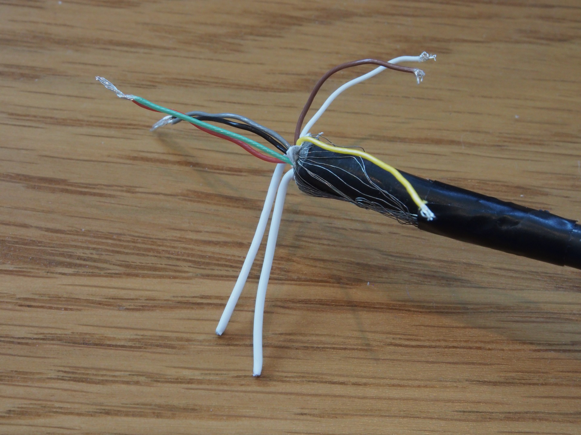
The power wires are red & green for + supply and black & grey for the - supply. These were paired together and connected up a a variable supply which has been set for 9.6V. The multimeter was connected in series to measure current and the supply switched on.
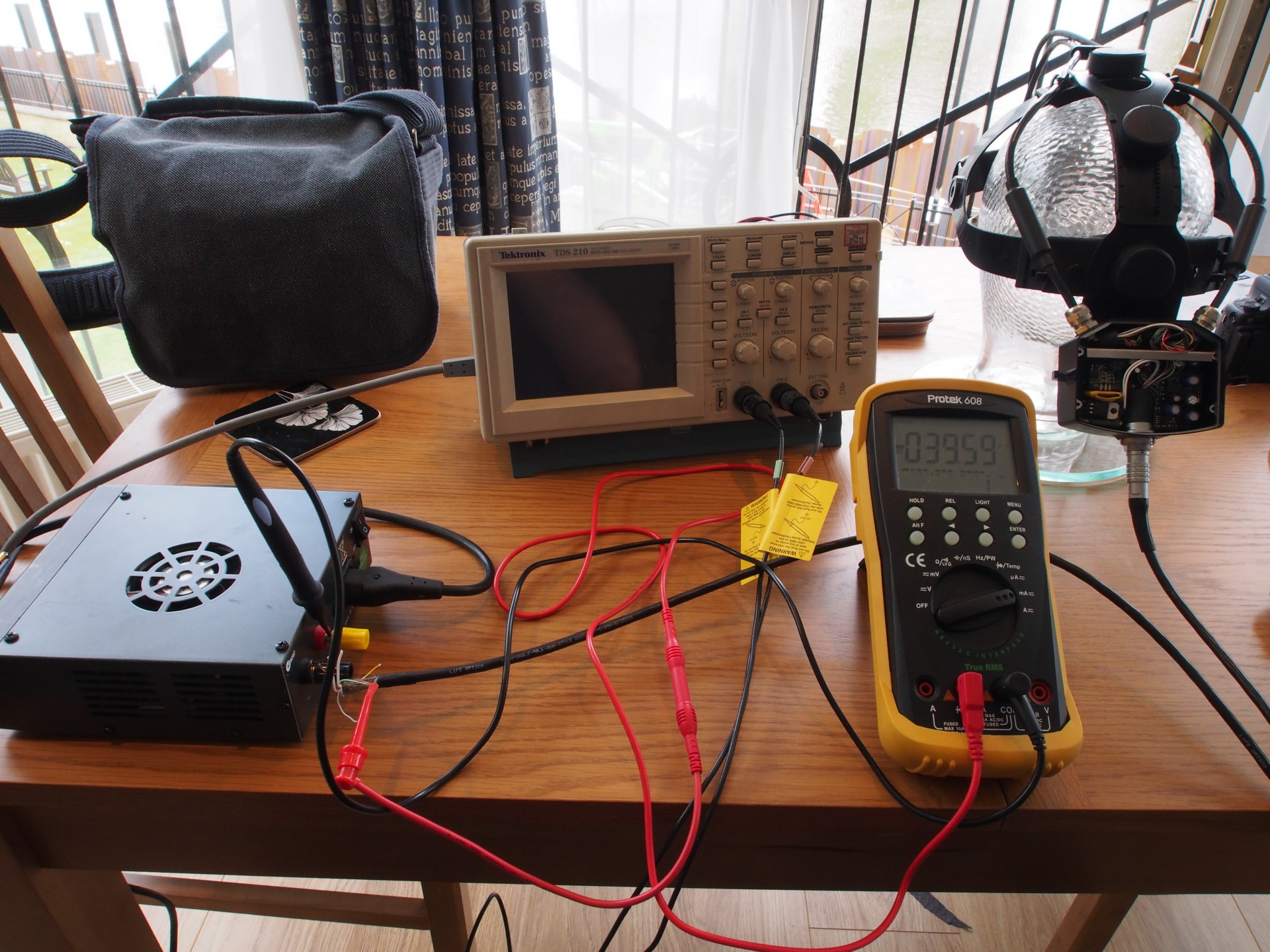
When the power is allied the device draws about 40mA at 9.6V. Not much else exciting happened. This seems like a reasonable amount of current and it doesn't suggest that the device is damaged by this voltage. No smoke or unusual smells were emitted (which is always good). The next step was to disconnect the multimeter and measure the voltage on the three mystery wires (white, yellow and brown). It turns out that all three measure 5V. This suggests that they are either digital outputs or digital inputs (with pull-ups). I turned to my scope to see if anything interesting was occurring on any of these lines.
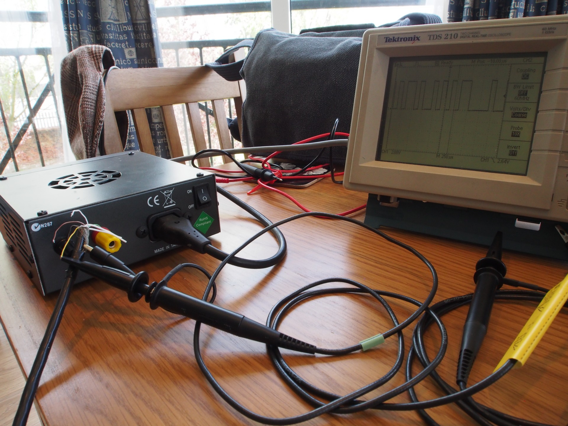
The brown and white wires do not deviate from 5V when power is applied but the yellow wire was far more interesting. When power is first applied we see something that looks a lot like TTL serial data.
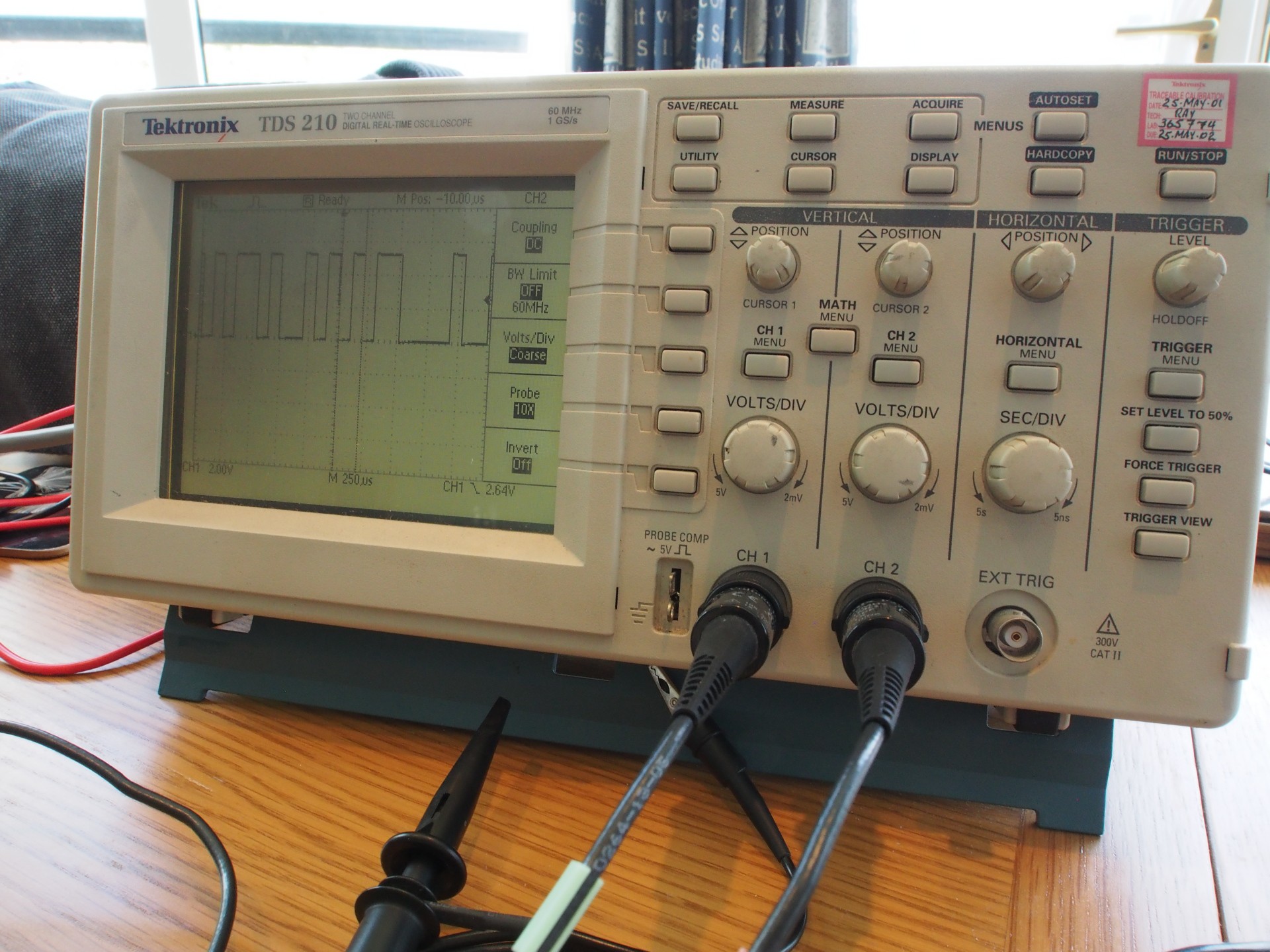
Using the cursors on the scope I measure the period of individual bits to be around 100uS. This should equate to 9600bps serial. The next step will be to hook this up to my laptop via an FTDI USB to TTL serial cable and see what the the device is sending...
Okay it doesn't really have a warranty to begin with but I'd still prefer not to break it. Given the lack of information available it looks like it's time to tear this thing open. There are two major parts attached to the head mount. The microscope optics and mechanical components are in the front unit. The wiring from the front unit then connects to an enclosure at the back.
As attacking the front optical/mechanical unit seemed to carry the greatest risk (possibly affecting the alignment of parts or allowing the ingress of dust etc.) I have decided to start with the electrical connections at the back. According to the manual, this small enclosure is designed to hold an a counter weight to balance the unit so it is not too front heavy. Weights can be added or removed as required and are held in by a small bolt running through an internal bulkhead. However, this weight does not occupy the entire volume of the enclosure. The connections run behind this bulkhead. Removing it (held by four small screws) reveals the enclosures other purpose. It holds a considerable portion of the electronics that drive the microscope.
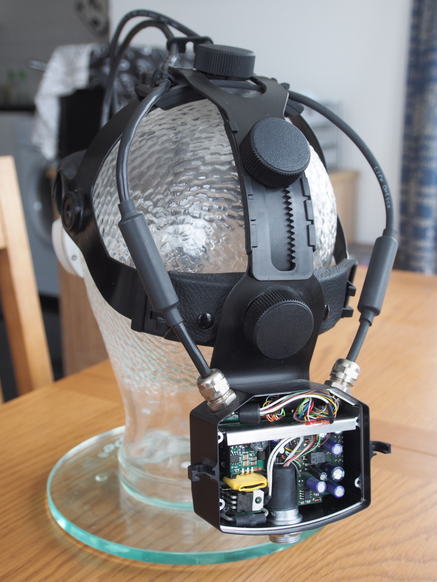
There are two stacked PCB's in this enclosure. The outer PCB contains what looks to be mostly power supply related circuity. It also has all of the electrical connections that run to the missing control box. The inner PCB is harder to see but at least one large IC is visible. The part number is obscured by a sticker that seems to indicate a firmware version so it is possibly a micro-controller.
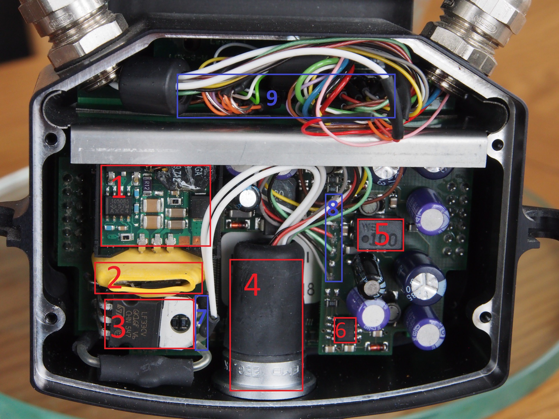
I've marked the interesting components in red and the external connections in blue.
It's worth noting that the grey and black wires from the control box are connected together by a trace on the PCB. The red and green wires are also connected together by a trace. This suggests that they may be the power connections. This is backed up by the observation that these two connections run through the common mode filter.
If the assumption about the mini-coax being for S-video is correct it really only leaves three wires (white, yellow and brown) for control of the microscope. The next step will be to attempt to power up the PCB and look at these signals on a scope to see if there is any activity.
As with any reverse engineering effort it's probably a good idea to get acquainted with whatever information is publicly available for this device before ripping it apart blindly.
A Google search turned up a user manual but unfortunately no service manual. The manual shows that the microscope control box runs on a rechargeable Ni-MH battery. From the images it appears to be a 4-cell pack. This could be a clue to the operating voltage of the microscope (alternative there could be a boost or buck converter in the control box). It also details that the microscope optionally has a PAL or NTSC camera and that it outputs S-Video. So we can expect to find a video signal from the microscope.
Google also turned up a press release from the company that produced the miniature stepper motors that are used to drive the focussing and zoom mechanisms. It goes as far as listing which specific motors are used. From this we can assume that device generates two phase unipolar stepper drive signals somewhere.
A search on Google patents also turned up a couple of interesting patents relating to the device. These deal mostly with the optics and don't not provide a great deal of information regarding the electronics. They do mention that an Infra-red range finder is used to determine the distance to target for the auto-focus system. So that is another piece of the puzzle.
Links:
Micromo application/press release
Create an account to leave a comment. Already have an account? Log In.
I developed the HW & SW for the head-set and foot-control so I have all docs...
But even if you get the specs of communication between these two parts, you wont be able to do much - it's a bit complicated...
So tell what is your problem with M5 varioscope and I'll try to help you.
Hi, I have an identical unit for repair. The problem is on power board (outer PCB shown in the pictures above) - the +5V and 3.3V are missing, the rest seems to be ok. Do you think you can help me with a schematic and/or PCB file?
Hi guys,
if you still need info on Varioscope M5 - I can help you....
I missed your reply, but I do still have the microscope. Any specific information, particularly relating to the communication protocol would be very useful and greatly appreciated. Disassembly of the optical block looks to be risky in terms of alignment. I did identify the main micro-controller as a Hitachi H8 part but attempting to dump the firmware is difficult because of its inaccessibility and a lack of dev tools for that micro.
You may already be past the point where this is useful, but the prompt you showed looks like the "forth" language. You can confirm by typing "save-forth" and Enter; I suspect, depending on dialect, it will dump a long report to the serial port. This report is the contents of the forth "dictionary," all the commands it supports, all the way down to 1+1. (Needless to say, only the latter part will be interesting.) Let's see what comes out when you try this. If my guess was right, then we may be able to find a 'zoom' in there. (I'm restoring an old mass spec which works this way.)
In the microscope world the conventional wire color for the Zoom function is orange and white. Just a guess
I have worked on Leica and Zeiss microscopes for 30 years. I'm retired now and just rebuild scopes and modify them. I've added Zeiss bodies to Leica stands and controllers. When you start the project again let me know. The Zoom and Auto focus are separate circut boards in standard scopes. The Zoom is parafocal with the focus. IE when you zoom the focus is in focus for all powers. I've never had my hands on this particular unit but if you have the unit far enough apart you can back trace the servo for the Zoom. In the Zeiss to Leica conversion above I had to run a separate power supply for the Zoom focus and to install a PWM . It worked fine. Voltage to the Zoom was 12v dc. If you screw up the alignment on the optics you can send me the head and I'll realign them. I can do that for any microscope. I'm in San Diego CA though.
Thanks for the information and kind offer. I just (about 12 hours ago) unpacked the microscope for the first time since moving countries. I was trying out the use of white high power LEDs as a light source when coupled into the fibre optic cable. It seems that simply butt-coupling the end of the bundle directly to the LED will be a reasonable approach although I did order a special TIR lens designed for fibre coupling to try out. The losses are going to be quite significant and it's probably not nearly as bright as the original short arc metal halide source but it appears to be bright enough. I could buy a suitable short arc source from eBay second hand but it's not cheap, generates a lot of heat and the bulbs are short lived and horrendously expensive.
I suspect the design will be quite different to other Leica microscopes considering they purchased the design from the Austrian company that originally developed it. I did get slightly further than I have documented here before I packed it up and have full control of focus and convergence. I just haven't been able to control the zoom. There is a diagnostic command that racks the zoom back forth though so the ability to control the motors via that interface must be there. The zoom and focus are all operated through a single board in this design. I removed the front cover and identified the Renasas H8 microcontroller that drives four ROHM stepper motor drivers to control the zoom and focus stepper motors. From poking around I believe the H8 board at the front is entirely responsible for controlling the optical assembly and the board at the back responsible for the power supplies, camera and routing of comms. I would like to attempt dumping the firmware from the H8 but stripping the optical assembly down to the point where I could probe it seems the be non-trivial. H8 dev tools aren't something I have easy access to either. I will continue trying black box reverse engineering first. Hopefully getting the zoom control is just a matter of time once everything is connected back up again.
Hi,
I own a Varioscope M5, tell me if can help you (without damaging my device). Cold you post some pictures showing the internals of the optical system?
Please let me know if you still want to proeceed with your project. I would like to learn more about the optics. But in this case the optics has to be disassembled and I'm quite sure that a re- allignment would be almost not possible anymore :-(
I do intend to proceed with the project. I did find one (low quality) image showing some of the optics from a patent. I'm not willing to disassemble this unit at this stage as it appears to be working.
What is now the actual status of the project? The optics by itself seems to be very interesting, so many features in such a small space. Do you have any inside of the optics?
The project has been delayed by a move from the UK to Australia. The microscope was just unpacked recently but life isn't quite settled enough for work to resume. Before the move I managed to get further with reverse engineering and did partly disassemble the optics. However, the majority are mounted in a machined block that I really don't want to disassemble. I'm concerned that the alignment may be quite a difficult to perform if anything is moved. There is a 16-bit CPU (H8/3694), stepper motor drivers (BA6845FS) and four stepper motors in the front. Reverse engineering of the control protocol had progressed a little bit further before the move and partial manual control of the optics was possible.
A description of how the optics work is here. The pictures leave a bit to be desired: http://pdfpiw.uspto.gov/.piw?PageNum=0&docid=07286287&IDKey=33BF5E19562C%0D%0A&HomeUrl=http%3A%2F%2Fpatft.uspto.gov%2Fnetacgi%2Fnph-Parser%3FSect1%3DPTO2%2526Sect2%3DHITOFF%2526p%3D1%2526u%3D%25252Fnetahtml%25252FPTO%25252Fsearch-bool.html%2526r%3D1%2526f%3DG%2526l%3D50%2526co1%3DAND%2526d%3DPTXT%2526s1%3D%252522Life%252BOptics%252522.ASNM.%2526OS%3DAN%2F%2526RS%
This might be the first Leica project at Hackaday. Nice find!
Whoa - Leica cameras are the top of the food chain as far as German designs go. I can imagine that M5 cost a pretty penny when it was new. I can't wait to see how that works for soldering. I usually use a head mounted magnifier when doing SMT work - my eyes aren't what they used to be. Something like this would be perfect. ... now to check ebay...
Become a member to follow this project and never miss any updates
 rawe
rawe
 Yann Guidon / YGDES
 ivorivetta
 Alan
Alan
Its Really Amazing and Informative, we are using many equipment in our Markham Gateway Dentistry In Canada and customers are really satisfied you can see things here https://markhamgatewaydentistry.ca