 Voja Antonic
Some more details...
All passwords are 15...20 character in length (which is random).
At least one lowercase, one uppercase character and one digit is guaranteed in each password
There are no punctuation marks or special characters, as not all servers accept them. But I shall add that option in setup, so you can choose it.
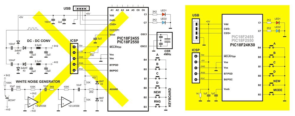
USB stack is open-source assembler software, by Bradley A. Minch. I have modified it so that it accepts uppercase/lowercase charracters, servicing <shift> bit in USB packet.
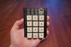
My friend asked me: Why don't you embed some PIN code, which can be typed directly on the unit, so that nobody can "borrow" it form you and use it? Good point, but you don't have to type PIN on this small and uncomfortable keyboard, you can add it at the more convenient way: type some extension on the existing passwords. So, when you generate new password, use the PC keyboard to type your "pin" on after it, and then store the extended password (there will be no conflict between USB keyboards on the computer). You have to do the same each time you use your password. This can be the same sequence of (say 4, or so) characters for all passwords.
GitHub link: https://github.com/vantonic/password_manager
Here's a brief demo:


 Guy Dupont
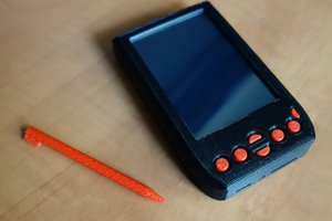
 brtnst
 Emilio P.G. Ficara
 Sven Gregori
I love the illustration there... ;)