 peter jansen
An update with a great deal of progress, including the design for the first revision of the imaging array, and a second iteration of the mechanical tomographic scanning framework.
From the last update, the initial characterization of the prototype modular radiation sensor looked very promising -- it's able to detect about 60-80 x-ray photons per minute at a distance of 6cm from the radioisotope source, which should be more than enough to generate an image. While characterizing the prototype detector I identified a number of revisions, and so my recent focus has been on working through everything required to build the complete imaging array.
Radiation Detector Revision 1
The prototype detector generally worked out rather well, and was designed to be amenable to a bit of wire wrap when issues came up (as an aside, I tend to use vias to attach probes and wire wraps, so my vias are often left untented for this purpose). I found a few issues that required a significant revision:
Things that worked well:
- Relatively low-noise: The detector has a very similar noise level (~+/-40mV) to what I've measured with the great Radiation Watch Type 5 (~+/-50-60mV). This is really an accomplishment for me given that I haven't designed many challenging analog systems, and low noise really enables this design.
- Detection level: The detection level was originally about 20 x-ray photons per BPW34S photodiode (@6cm) per minute, which is really very reasonable for a first pass. The Type 5 in the Arducorder Mini detects about 500 photons at this same distance, but it has a factor of 13.3x more detection area (so we'd expect the BPW34S to detect around 38 photons per minute, normalizing for detection area). Given that the beautiful First Sensor X100-7 photodiode used by the Type 5 is specifically designed for radiation detection and has a cost of about $100, while the BPW34S photodiode is a ~$1 part, we're really doing very well.
- Increasing Detection Level: The last post showed that the BPW34S photodiodes can be stacked in parallel, increasing the detection rate to ~60-80cpm, while not decreasing spatial resolution -- so we're doing very well here. A few dollars in inexpensive photodiodes is functionally getting us very similar performance to the fantastic X100-7 photodiode (for this task), and we're (again) really doing very well.
- Digitally adjustable: The comparator threshold can be digitally adjusted using an AD5160 digital potentiometer, and this is really handy to be able to adjust the detector's output to a desired noise level.
- Modest Soldering Skills: The board was designed to require only modest surface mount soldering skills (0603 passives, and SOIC ICs with the exception of the digipot), so they can be hand assembled relatively quickly.
Things that needed work:
- Microcontroller: I'd initially hoped that each modular radiation sensor would a be a "smart" detector, having it's own digital interface to ease data collection. Unfortunately even with my first pass at isolating things the microcontroller introduced too much noise into the analog portions of the system, and had to be removed.
- Analog to Digital Conversion: I've been very interested in developing a detector that can do very crude spectroscopy / energy level differentiation, to help render more informative scans. I've been crudely doing something similar to this with the Arducorder Mini, measuring the pulse widths from the Type 5, which tend to correlate with pulse height -- but of course actually measuring the pulse height should be much more accurate. To do this I'd piped the amplified analog voltage (before the comparator) to one of the ADC channels of the PIC24FV32KA301, which has a 12-bit ADC, at a 100Ksps sample speed. Unfortunately while some of the very largest peaks could reach ~10uSec (100Ksps) in duration, most of them are much shorter -- on the order of ~1uSec (1Msps). I don't have a lot of experience with fast analog signal peak detection, but I suspect one would require a significantly more complicated (and expensive) circuit to do this well. I'm very interested in this, but it will likely require more thought, and (unfortunately) likely won't make it into this iteration.
- Gain: I increased the gain on both the preamplifier and dual amplifier stages.
- Shield: A grounded foil shield surrounding the sensor is absolutely critical, but I had neglected to put a solder point on for the shield in the previous iteration -- so this was added in.
- Size: In order to fit into the 6" diameter enclosure symmetrically, the modular detectors needed to be reduced to a length of no more than 30mm, which required a bit of work (see figure below).
- Easy stacking: The photodiode stacking is giving near-linear increases in detection efficiency for low numbers of photodiodes, which is incredible, but I needed a simple way to make this compatible with surface mount soldering. I redesigned the footprint for the BPW34S to allow a stack of up to 4 photodiodes to snugly fit in a special slot, and be surface mount soldered in a normal reflow process. They'll still have to be hand placed, but a few seconds of work is easily work it for increasing the detector's performance by a factor of 3 (!).
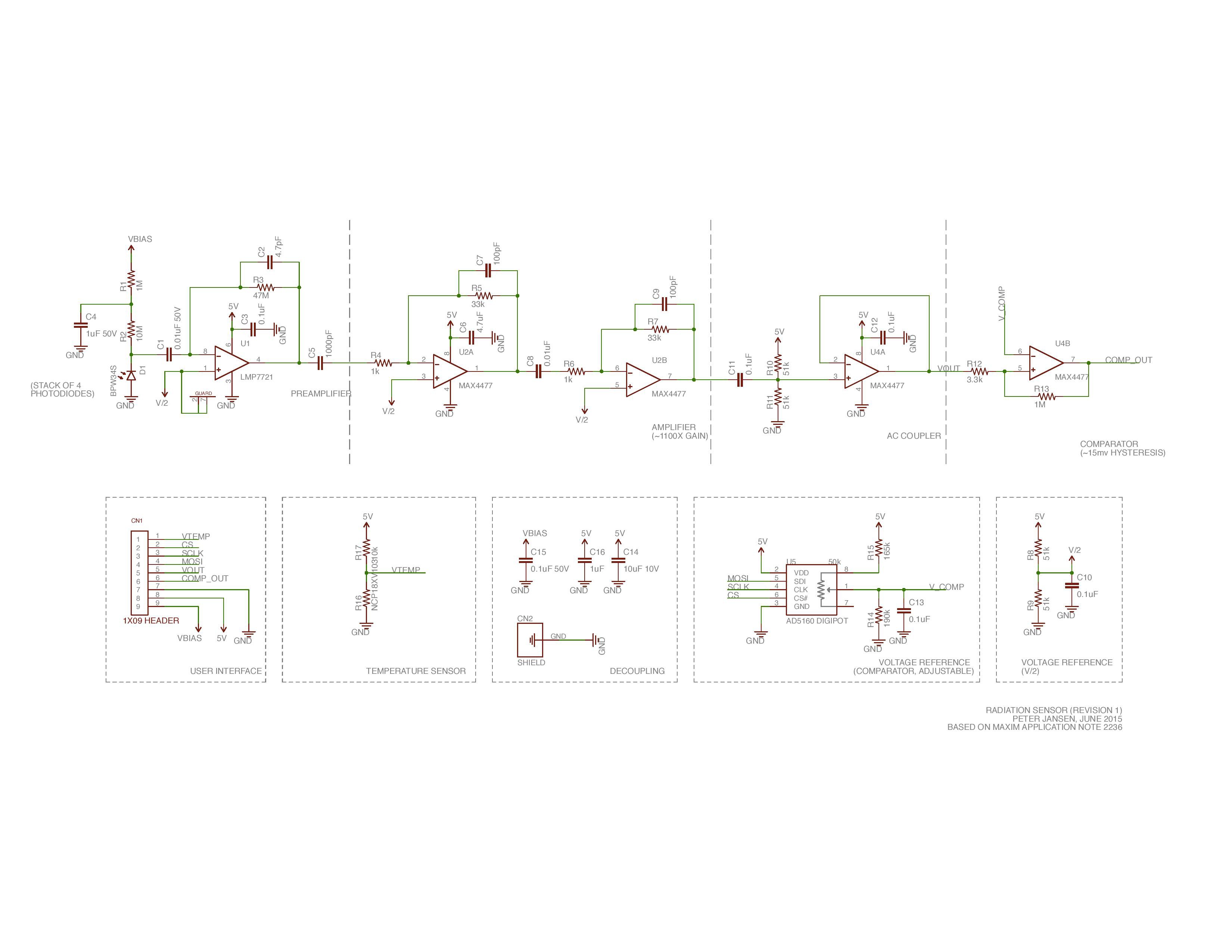
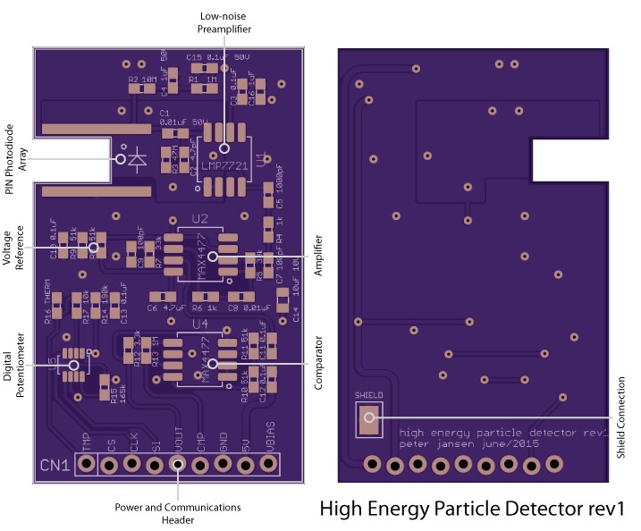
The schematic for the modular radiation detector (revision 1) is pictured above. Most of the revisions affected component values and mechanical layout, with the exception of moving the microcontroller offboard. PDFs of the schematics (as well as the Eagle files) are available in the OpenCT2 Github repository.
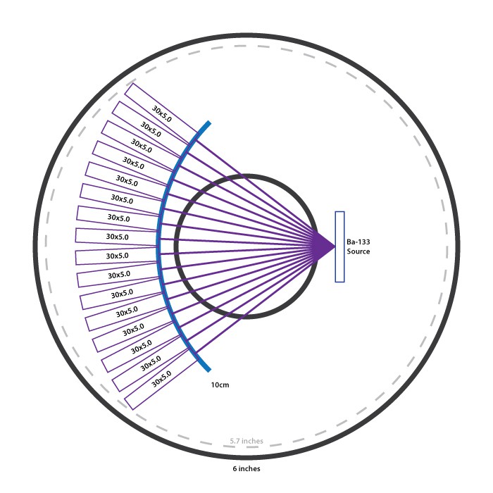 With stacking the BPW34S photodiodes, the total length of the prototype detector had increased to about 40mm. With my completely arbitrary and aesthetic desire to fit the entire device into inexpensive 6 inch PVC tubes (with a 5.7" inner diameter), the detector board had to be reduced to a maximum of 30mm in length to fit symmetrically. Sacrificing a bit of height for the sake of symmetry, this first revision of the detector comes in at ~30mm x 48mm, allowing for the symmetrical design above.
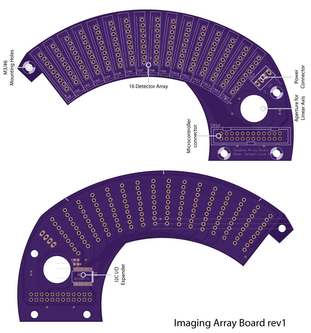
Imaging Array Board
The imaging array board (above) functions to hold in place 16 of the detectors that together make up the imaging array. Here, each detector is equidistant from the source (at 2.25 inches or ~6cm), and rotated about 5 degrees with respect to the neighbouring detectors such that their photodiodes are facing straight towards the source -- the orientation where they're most efficient.
I really enjoy the shape of this board, and it's certainly one of the more unusual designs that I've had the opportunity to put together. It's functions are largely mechanical, but it also includes a header to connect a separate Microcontroller Board (below) that interfaces to each of the 16 detector modules, and performs the actual counting. While the comparator output pins of the detector modules are all brought out to the microcontroller connector, the SPI pins for the digital potentiometers are brought out to an I/O expander (a Microchip MCP23017) to handle toggling the 16 independent chip select (CS) lines. It's not entirely clear whether the digipots on each detector will all have the same calibration setting, or whether they'll each require slightly different settings, so here on this prototype the I/O expander is included to allow for the possibility of setting each one individually. It's important to make our mistakes cheaply, after all.
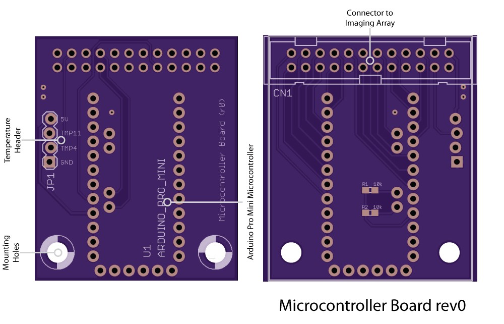
The Microcontroller board (above), from a functional perspective, needs to wait for detection pulses from each of the 16 detectors, count them over a period of time, and then communicate the total number of counts from each detector (after about a minute of collecting data) to another board, say a Raspberry Pi, that's controlling the whole show, and generating the images.
Nominally this is a perfect job for an FPGA, but they're a little challenging to program, and it's been a few years since I've tinkered with one. Many of the larger Microchip microcontrollers have 16 or more Change Notification (CN) I/O pins, which can trigger interrupts, and would also be very suitable for this task -- though that would require soldering a TQFP. While I would normally make this decision, I'm continually trying to be attentive to making open source projects accessible whenever possible -- I tend to design projects that are extremely challenging to assemble for the average maker. For example, the Arducorder Mini includes a fine-pitched 100-pin TQFP for the microcontroller and many other leadless fine pitched parts, and other than the handful that I've made and sent out, I've not yet heard of an Arducorder made in the wild -- although I'm very happy that parts of the design, like drivers and reference schematics for the Hamamatsu Microspectrometer, are being used. One of the best feelings that you get as an open content author is when people make, use, and modify your designs, and I'm making an effort to design the OpenCT2 such that the most complex bits could be assembled by a capable undergraduate student with very modest surface mount soldering exposure.
In light of this, I've opted to include Sparkfun's great Arduino Pro Mini, which is extremely easy to solder, inexpensive, and has *just* enough pins to cover the task. It can also very easily communicate to a Raspberry Pi (or other host computer) with an FTDI USB->Serial cable, and can be reprogrammed with the popular Arduino IDE, which should encourage tinkering, learning, and experimenting from the community and budding computed tomography students/enthusiasts.
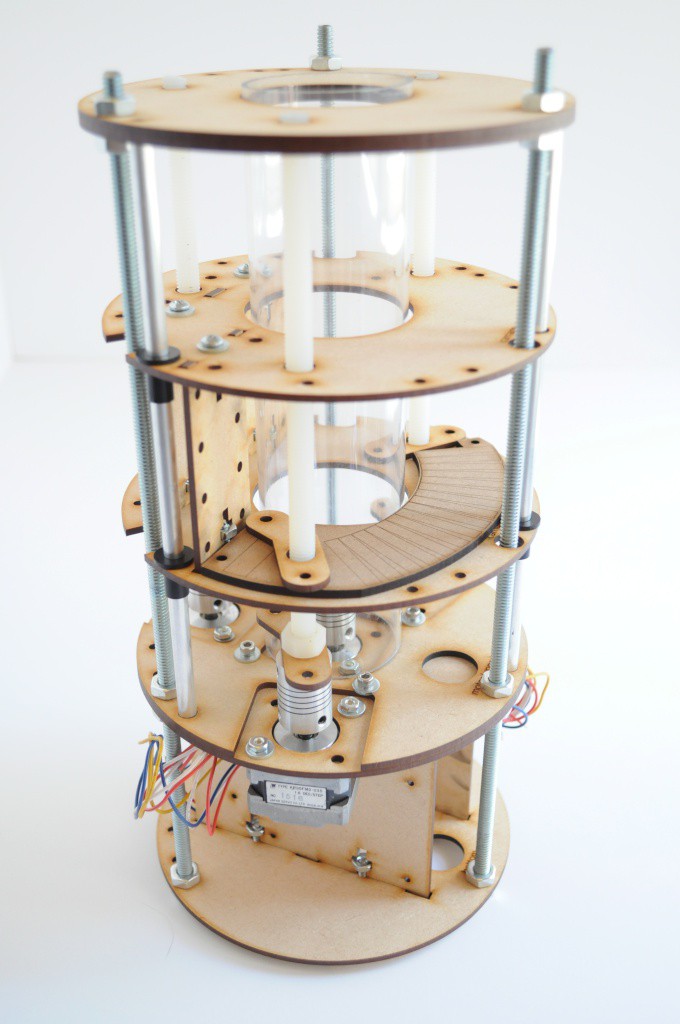
Physical Tomographic Framework
While I've been waiting for the boards to be fabricated, I've had a bit of time to tinker with the mechanical bits of the project. Both the imaging array and the mechanical tomography machinery have physical constraints (for example, a lead screw can't go through a detector), and so the design of both the imaging boards and the linear stages had a lot of back-and-forth.
Lately I've been really interested in round/organic designs, and also in arrays of things -- and so I've tried to include these themes into this project, both with the array of detectors, and the interesting design challenges that come with making something that's round and has a lot of moving parts.
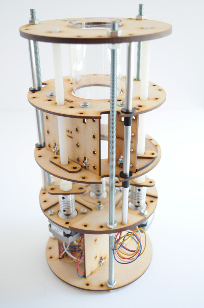
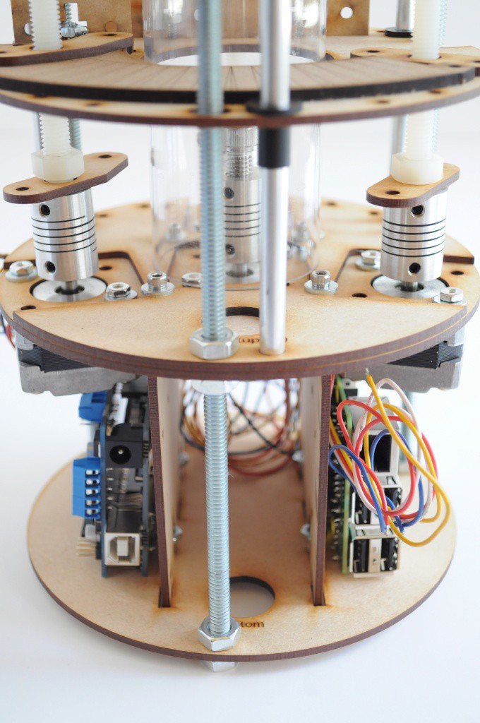
The current design is about 11 inches high and just under 5.7 inches in diameter, which allows it to easily housed in a standard 6 inch PVC plumbing pipe from a local hardware store (like Home Depot).
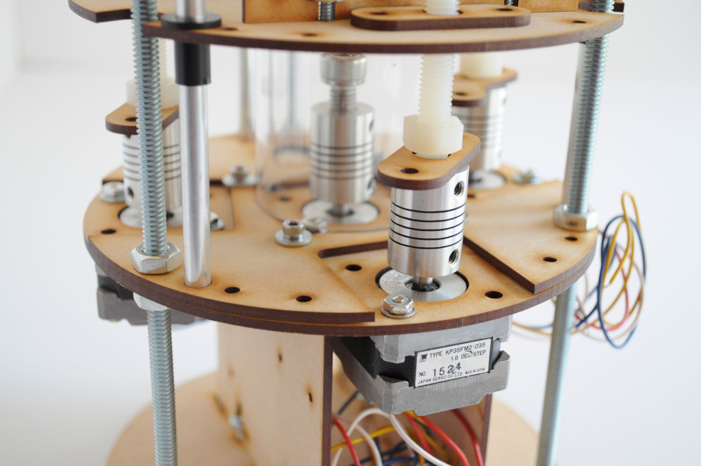
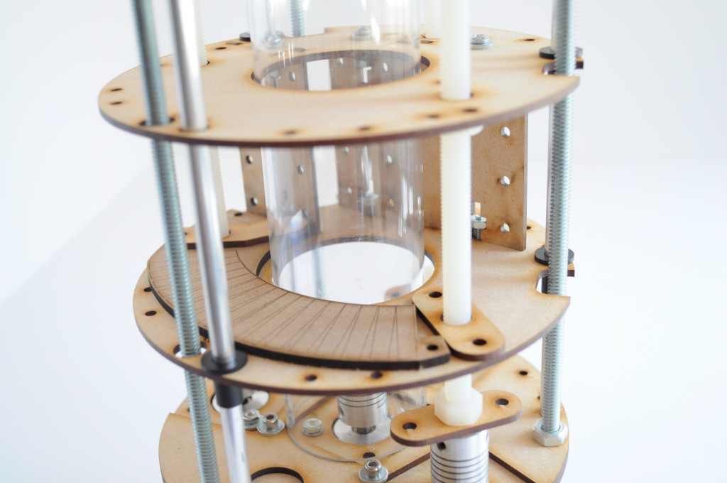
The design has two main axes of motion, which is greatly simplified over the original OpenCT -- a linear stage, that moves the entire imaging array up and down, as well as a rotary stage, that rotates the sample 360 degrees (here represented with the clear acrylic sample container). Previously I'd used only two lead screws to index the linear stage, but this was really wishful thinking, and the staged walked from side to side quite a bit instead of moving smoothly.
Here, I've added an extra motor to the linear stage (bringing the total up to 3), which should make the motion much smoother, and add a bit more support for the imaging array, the Barium 133 radioisotope source, as well as a generous amount of lead shielding. Not having a lot of experience with things made out of solid lead, you /know/ it's going to be heavy before you pick it up, but it's still way heavier than you expect.
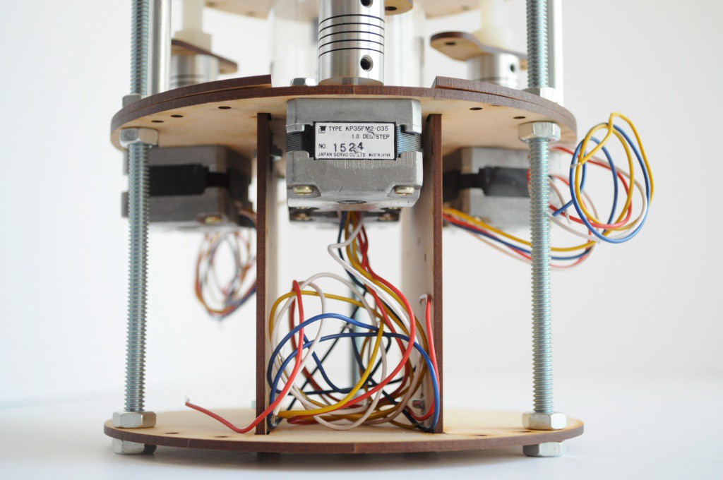
The motor for the rotational stage was originally a NEMA17, but I've sized this down to a NEMA14 to match the other motors, given that it shouldn't require very much torque to get the sample moving. This also keeps the design (and the BOM) a bit simpler.
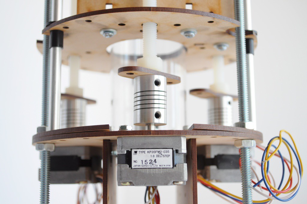
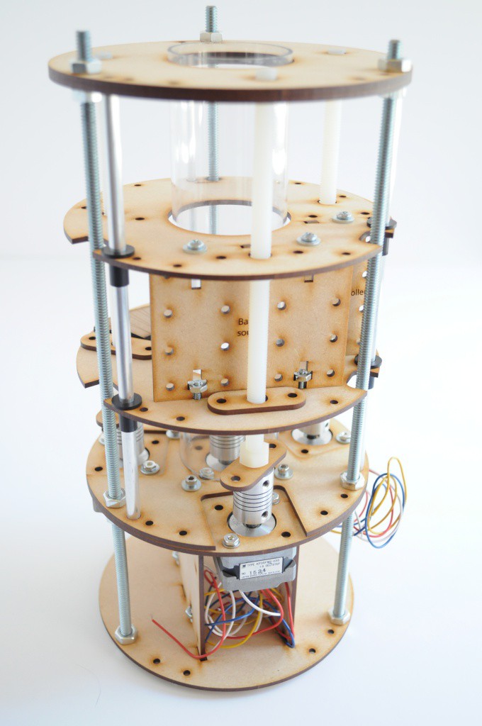
The couplers are the inexpensive aluminum flex couplers that go from the M5 stepper motor shafts to the M8 nylon lead screw. These
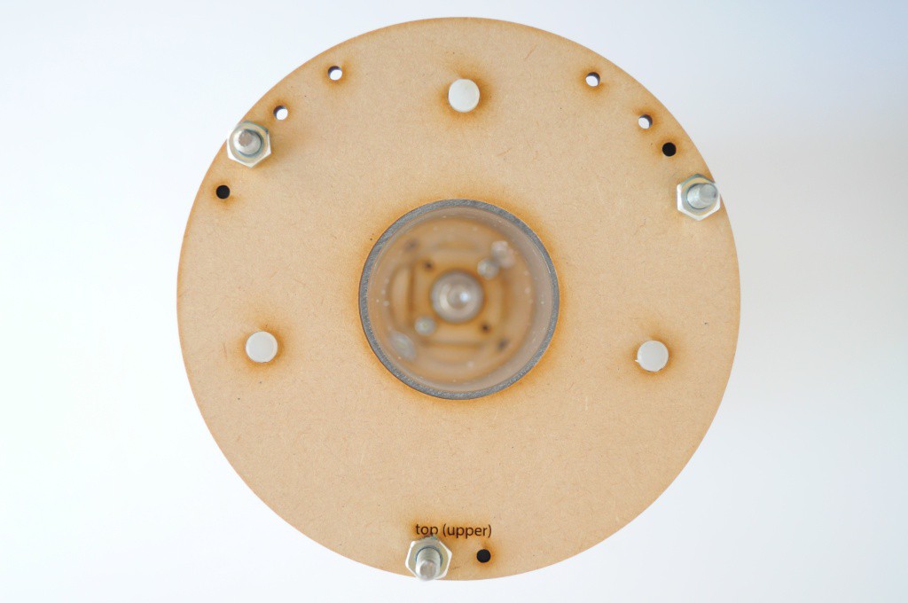
From the top down, here we can see the top supports for the nylon lead screws, as well as the tops of the three steel threaded rods that extend from top to bottom, and are used as a structural supports for the entire mechanism.
Imaging Array Carriage
The Imaging Array Carriage (above) houses the imaging detector array and source, and indexes up and down around the 2-inch diameter acrylic sample container. Here a mock-up of the imaging array board can be seen, to give a rough idea of fit while the boards are being manufactured.
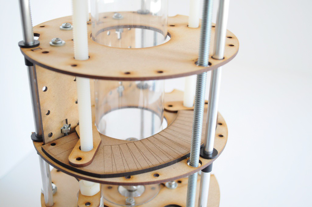
At about 70mm in height, the imaging array carriage is a little higher than I was expecting, but it's very workable for a first pass. The height largely comes from the 48mm required for each detector, not including the connector and the Imaging Array Board itself.
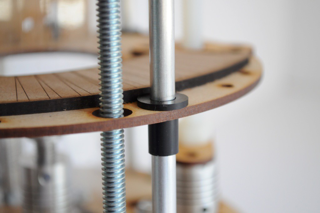
Like the two linear axes inside of the original OpenCT bore, I've found that inexpensive aluminum rod (here 0.25 inch) and nylon bushings available anywhere from McMaster-Carr to a local hardware store work very well as linear slides.
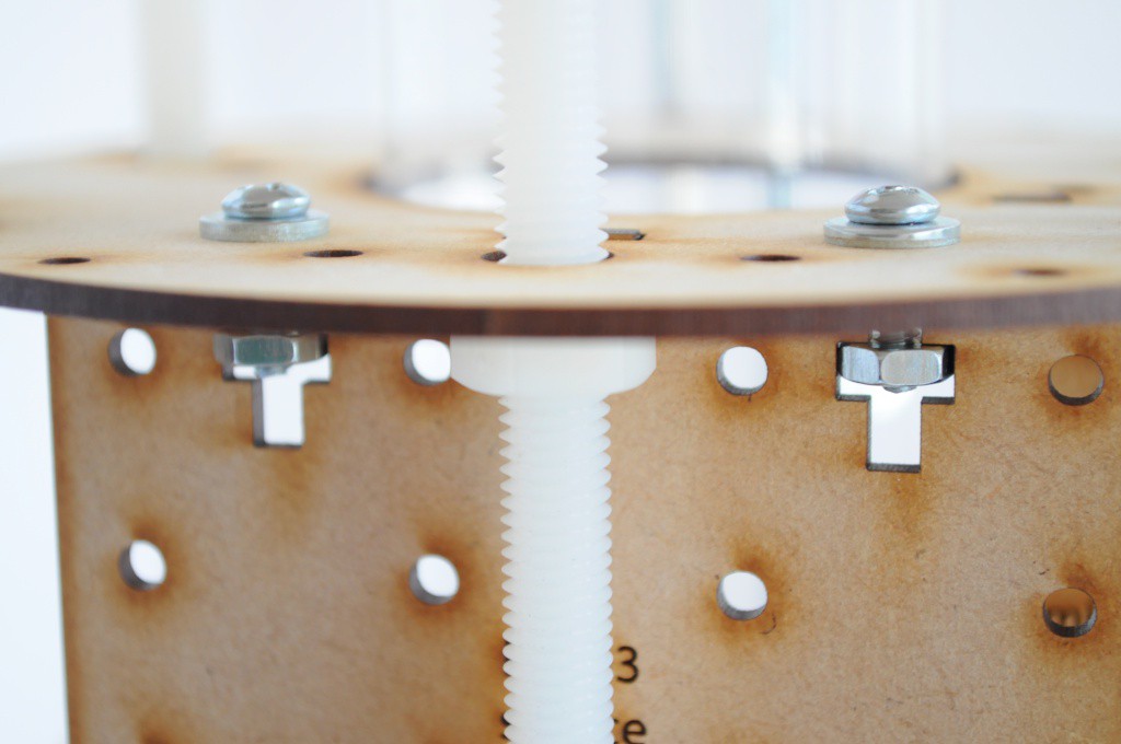
I've also been using nylon lead screws lately for projects where keeping things light is an asset, and absolute precision isn't required. With traditional stages assembled using steel threaded rod, I've found that unless you're willing to use rod designed for linear motion, it often has very slight bends or otherwise generates alignment problems that can be frustrating to deal with. Here, the nylon lead screw (and nylon nut) are extremely inexpensive, light, and have a bit of give to help adjust to any alignment issues. Note that the nuts are normally sandwiched in between two pieces of MDF, but they haven't yet been installed in this picture.
Mechanical Controller
It's my hope that the project will have three main contributions, each dependent upon the last:
- An inexpensive high-energy particle detector
- An imaging array and supporting hardware, composed of many detectors
- A physical mechanical platform for desktop computed tomography or scanning, whether coupled with the above imaging array, or any other sensor or imaging array a student, researcher, or enthusiast might use.
To make things accessible, I'm trying to keep each component as easy as possible for folks to assemble. While each detector (1) does require modest surface mount soldering exposure, I'm trying to design the imaging array (2) to largely require only through-hole soldering, and the mechanical CT platform and control electronics (3) to require minimal soldering and use as many off-the-shelf components as possible -- something that you might see as a set of instructions in Make Magazine rather than a laborious set of assembly instructions sent to a contract manufacturer.
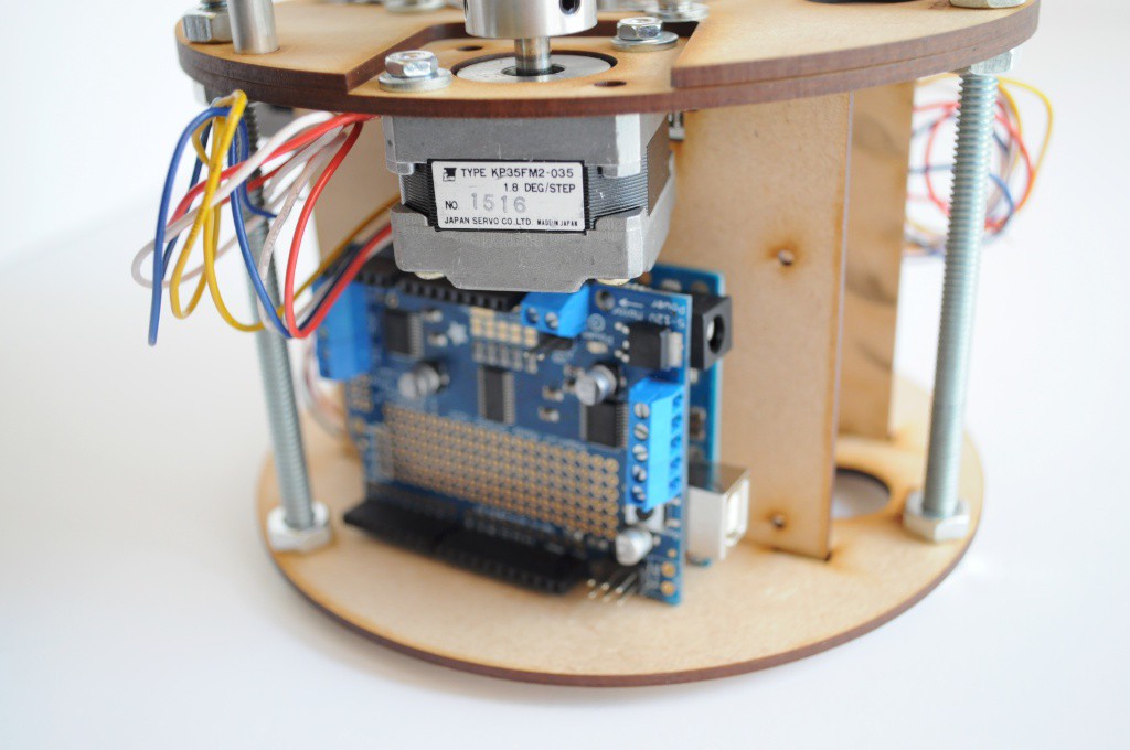
With this goal in mind, I'm trying to see if a regular Arduino Uno and Motor Shield (to control the motion) coupled with a Raspberry Pi (for a Wifi-enabled user interface) will be sufficiently powerful to do everything that needs to be done, while keeping everything very off-the-shelf and accessible.
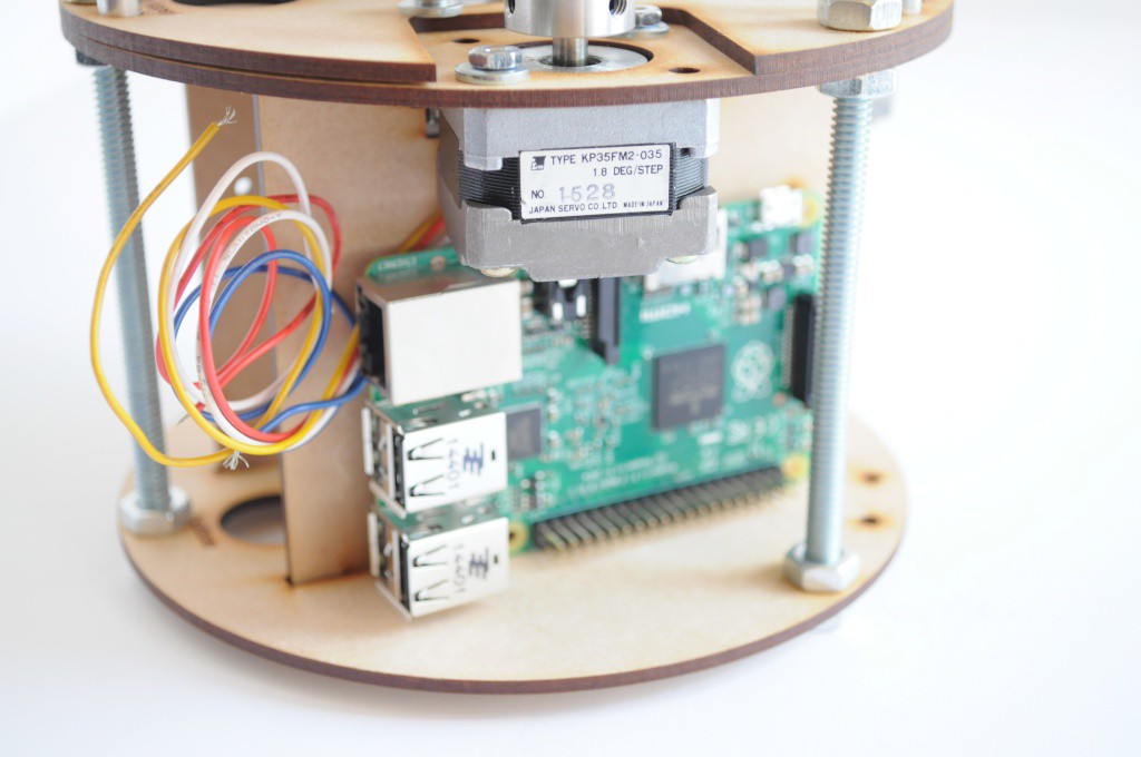
Both the Arduino Uno and Raspberry Pi currently have mount points at the bottom of the tomography platform, just under the motors. They're mounted outward to allow easy access to the various connectors, and make assembly and maintenance as easy as possible.
Thanks for reading!
Discussions
Become a Hackaday.io Member
Create an account to leave a comment. Already have an account? Log In.