 Florian Cliquet
Warning : A smoke detector is a safety device, any modification could affect its normal operation so kill people and cats.
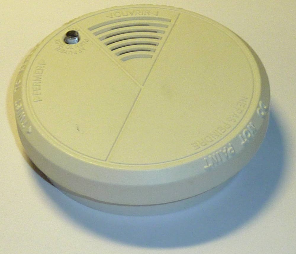
It all started when I recovered a faulty smoke detector, but it can also be buy for around 10$.
Repair it
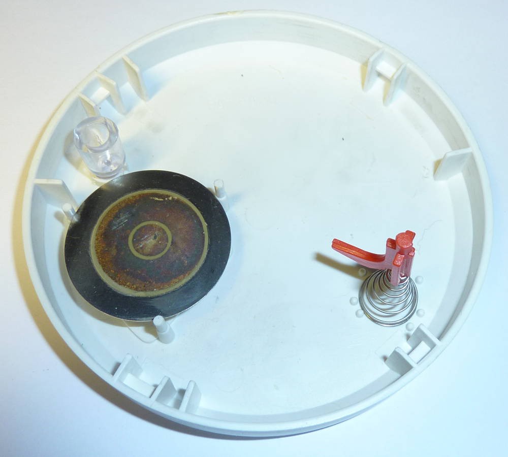
It was no longer ringing due to a piezo problem. I just changed the broken component and it was doing its job again.
Connect it
I thought it would be great to be able to connect several of these smoke detectors together to be able to :
- Supply them
- Make all them sound when one detect a problem
- Detect which one smell some smoke to trigger some actions (SMS, e-mail, ...)
To connect them together, I prefer wires, especially for safety devices. Moreover add a wireless connection will significantly decrease the battery life. But the technique described above can be used to work wirelessly with something like a standalone ESP8266.
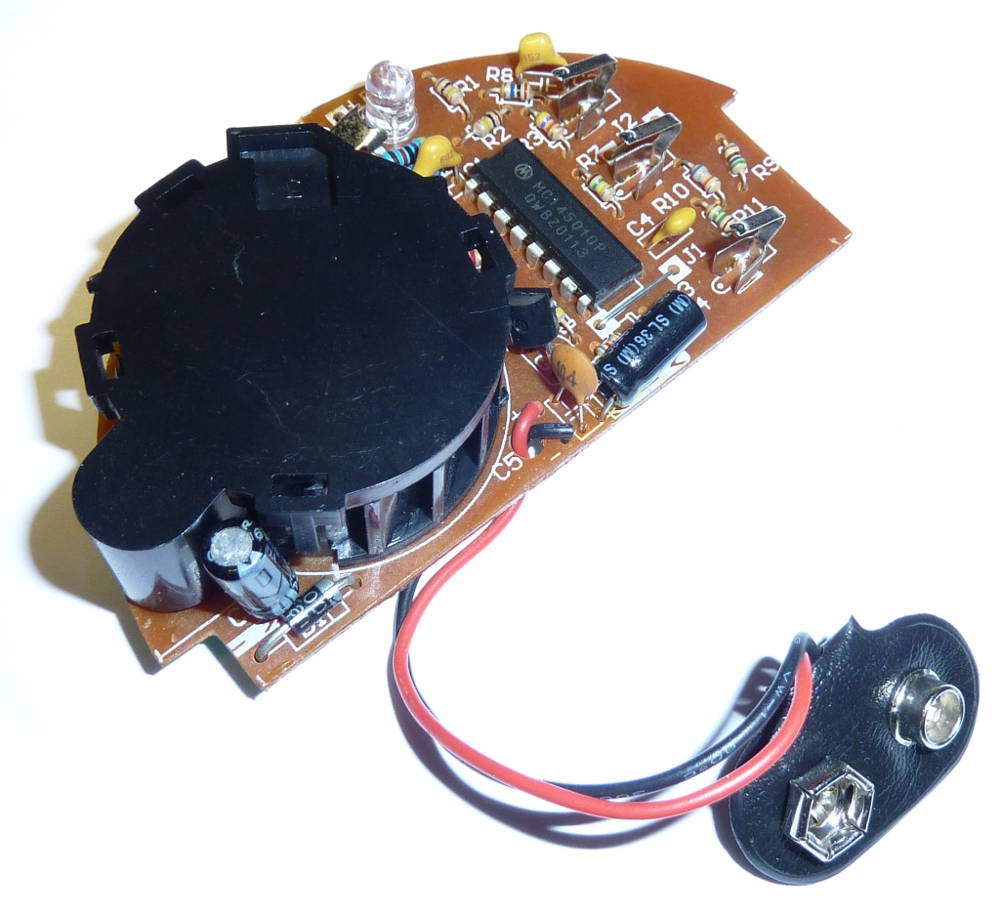
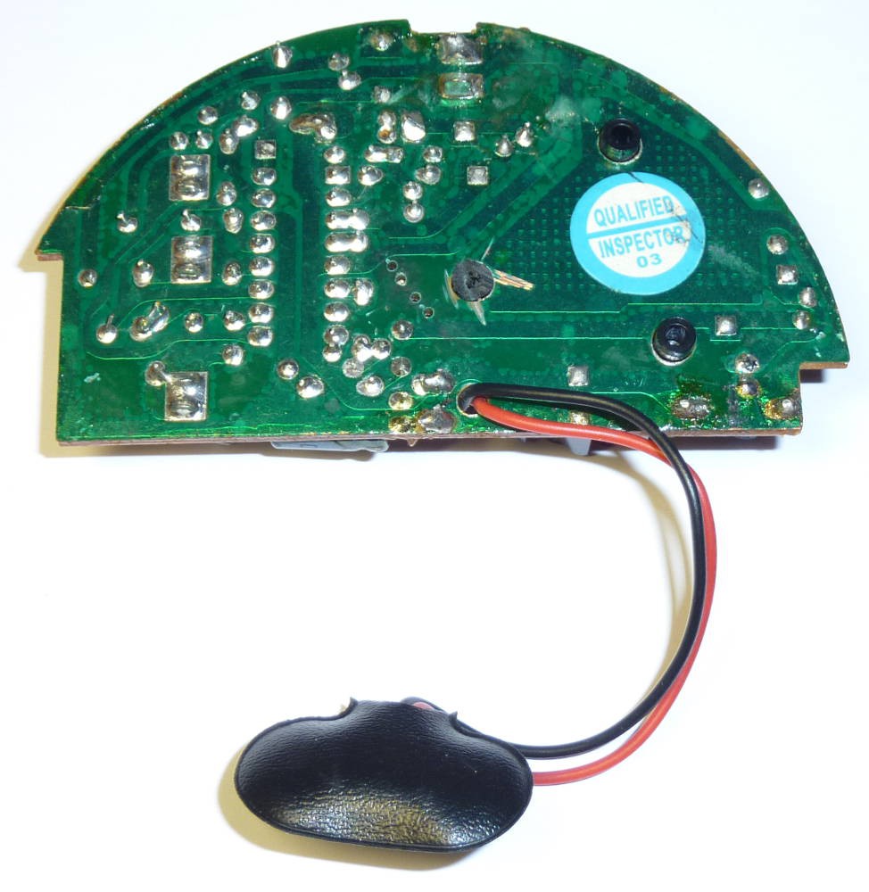
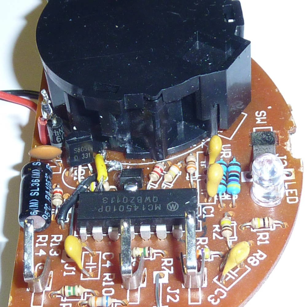
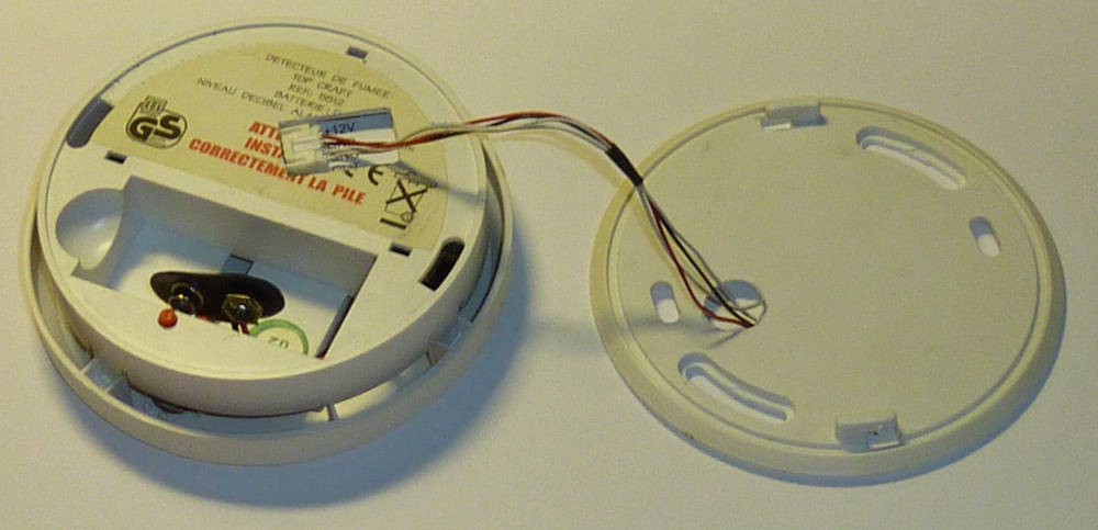
After a quick teardown, I found out that the detector was powered by an MC145010P, a photoelectric smoke detector IC from Freescale.
Power Supply
Normally the detector is powered by a 9V battery. For safety reasons, I want to keep it but also add an external power supply to use the battery only as a backup.
The IC works between 6V and 12V. I chose a simple hot swap power supply solution composed with diodes as represented on this schematics.
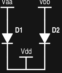
Two power sources separated from the IC by two diodes. The source with the highest voltage supplies the IC, in case of failure of one source, the other take over.
ConnectivityThe datasheet indicates that the pin 7 is an I/O used to connect up to 40 units together in a wired-OR. Which simplifies everything.
When a detector detects a problem or when its test button is pressed, it put the bus high.
All the other detectors ring but don't flash to indicate the problem.
Add Connector
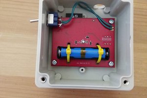
To easily install the detector and replace its battery I first added a connector.
First I drilled some holes for my connector where I found some place and cut a bit of plastic to make some room.
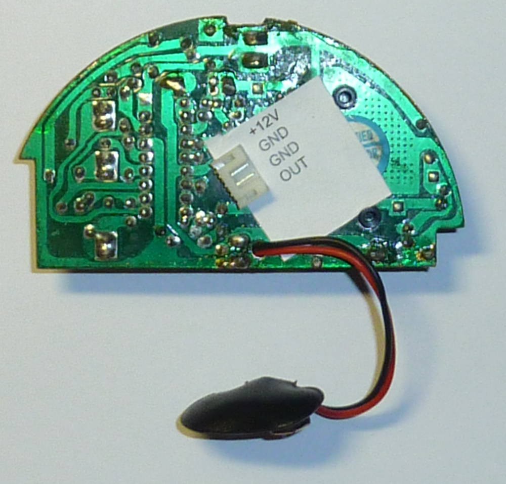
I soldered two diodes for the power, one wire for the bus (yellow) and one for the ground (black).
Here is the final result with a paper, to indicate the wiring and look cleaner when it will go back in its case.
The case must also be cut to give an access to the new connector.
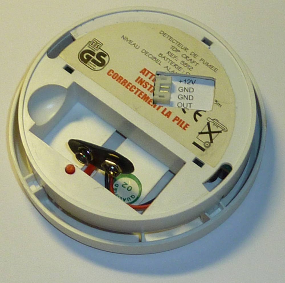
The fixing plate also need its hole.
Now we can link them together and supply them with 12V.
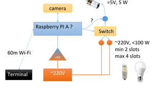
Interface with a microcontroller
The following schematic allows any microcontroller (ESP8266, Raspberry Pi, Arduino, ...) to detect a problematic situation with the input pin and to force them to sound with the output pin.
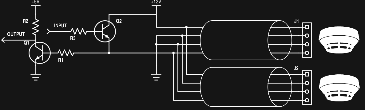
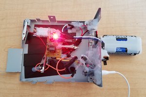
The result on a breadboard with a switch as input and a LED as output indicator.
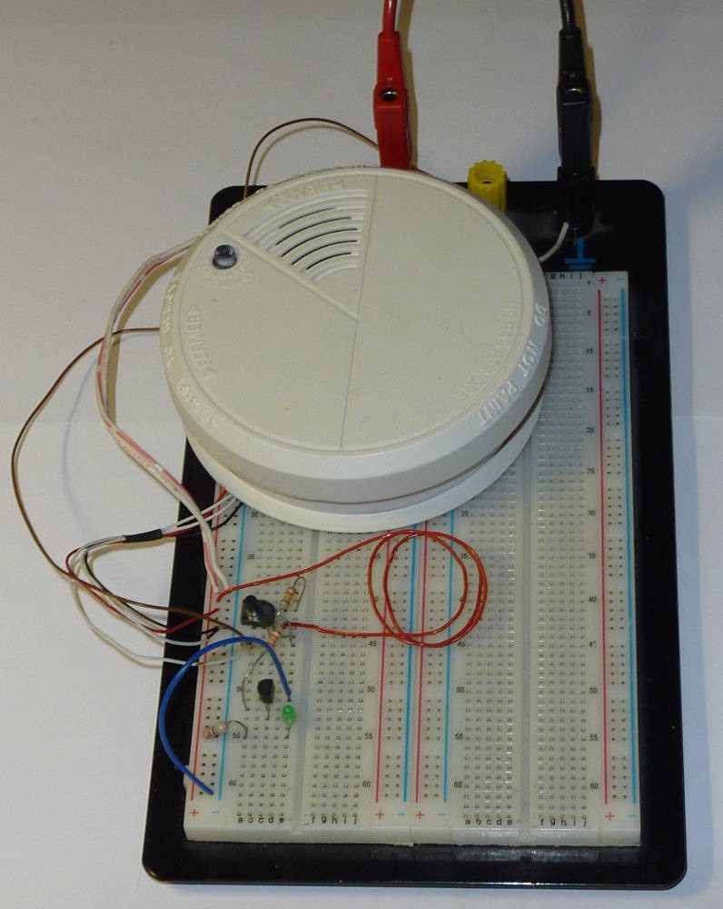
With this schematic, we are not able to detect which one detect the problem.
In order to achieve that we have to isolate each sensor buses and use two different voltage levels so we could differentiate when a problem is detected by the sensor to when we force the sensor to sound.
If any one have an idea, they are welcome.
Next schematic is coming…

I've just discovered my detector has a piezo problem, too. Where did you find a working piezo or how did you fix the problem? Detector is working but the sound is very quiet, I cannot even determine if this is a mechanical problem - I've tried cleaning the piezo and contacts, bending the contacts, many things but it just won't work. Any advice would be appreciated, and I think I'm going to follow up on your project once I get my detector working. It even has those signal ports available =)