John Leeman
Any fine details and lots of photos/resources/links are in the GitHub repo. You can learn a lot from your new compass/magnetometer! In addition to learning about the electronics and hardware, you can learn about magnetic fields and the Earth's geodynamo.
0%
0%
3D Compass
Visualizing the Earth's magnetic field vector in its three dimensional glory.
Become a Hackaday.io member
Already have an account? Log in.
Just one more thing
To make the experience fit your profile, pick a username and tell us what interests you.
Pick an awesome username
hackaday.io/
Your profile's URL: hackaday.io/username. Max 25 alphanumeric characters.
Pick a few interests
Projects that share your interests
People that share your interests
 Edwin Hwu
 arturopelayo
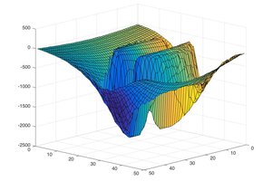
 Myrijam