 John Leeman
-
1Step 1
3D Printing Brackets
- Print 1 top and 1 bottom bracket. 60% infill and a raft are recommended.
- Using a soldering iron, insert the heat-set thread inserts. Eight in
bottom plate, 4 in riser posts, 4 in Arduino mounts. Two in top plate for
magnetometer mounts. See the demo video below (not mine, borrowed)
-
2Step 2
Top Plate Assembly
- Attach the magnetometer with 4-40 nylon screws. Shear the excess length flush
with the bottom of the plate using a hobby knife. Be careful to not break
the superstructure on the printed part.
- Place the capacitor into the cut-out and secure with a drop of hot glue.
- Solder ~5 cm of wire onto the data in line on the 16-element ring.
- Place the 16-element NeoPixel ring into the vertical ring holder. Thread the
data-in line through the hole in the bracket. This ensures that data-in, V+,
and GND are all accessable. Secure with a drop of hot-glue.
- Place the 24-element NeoPixel ring onto the riser posts. Line up the data-out
pad to be near the data-in line on the smaller ring. The LED should be directly
above the mounting post. Secure with hot-glue on each post.
-
3Step 3
Bottom Plate Assembly
- Secure the Arduino RedBoard to the base plate with 4-40 nylon screws. Shear
the excess length flush with the bottom of the plate using a hobby knife.
-
4Step 4
Attaching the plates
- Using the 4-40 nylon screws, attach the top and bottom plates. Shear
the excess length flush with the bottom of the plate using a hobby knife. You
may prefer to do the wiring with the screws out for easy access, but it
shouldn't be too much of a problem.
-
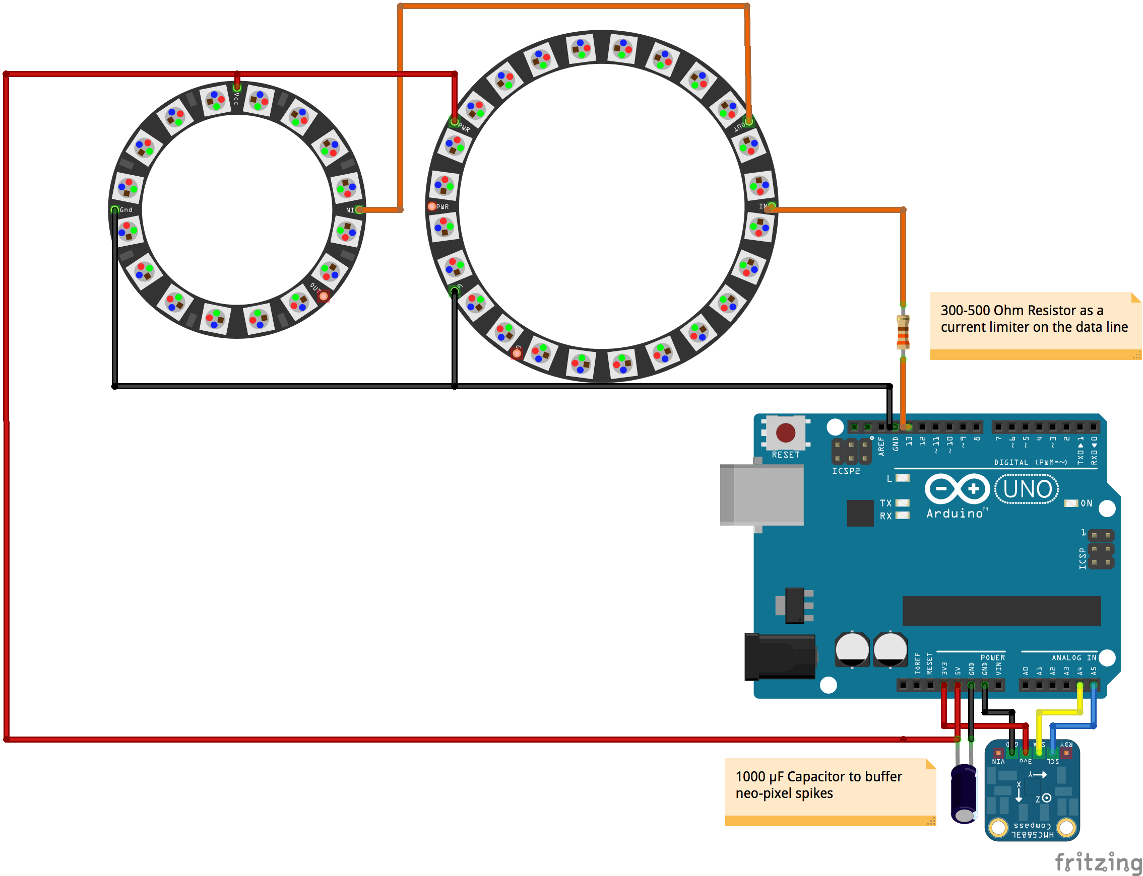
5Step 5
Wiring
- Trim and solder the data-in wire on the vertical ring to the data-out pad
on the 24-element ring.
- Connect the data-in pad on the 24-element horizontal ring to pin 13 on the
Arduino. The resistor goes in-line here as well. You can use 0.1" header to make this easier to assemble and troubleshoot.
- Connect a ground pad from the 24-element horizontal ring to a ground pad
on the 16-element vertical ring.
- Connect the second ground pad on the 16-element vertical ring to the ground
size of the capacitor (marked with -- on the case).
- Connect the ground side of the capacitor to GND on the Arduino. Header can
make this easier.
- Connect the power pads of both rings to the positive side of the capacitor.
- Connect the positive side of the capacitor to +5VDC on the Arduino.
- Connect the GND, SDA, and SCL pins of the magnetometer to GND, SDA, and SCL
on the Arduino.
- Connect the power pin of the magnetometer to the +3.3VDC pin on the Arduino.
![]()
-
6Step 6
Programming
See the linked GitHub repository for the code and more resources!
- Install the [NeoPixel](https://github.com/adafruit/Adafruit_NeoPixel),
[Adafruit Sensor](https://github.com/adafruit/Adafruit_Sensor), and
[Magnetometer](https://github.com/adafruit/Adafruit_HMC5883_Unified) libraries.
For help, see the [library tutorial.](https://learn.adafruit.com/adafruit-all-about-arduino-libraries-install-use)
- Connect the Arduino to your computer and upload the code in the Arduino/Vector_Display directory (see the [Arduino guide](http://arduino.cc/en/Guide/HomePage)) if you need help uploading programs to the Arduino.
- Play with parameters such as brightness and grading to create your own display!
3D Compass
Visualizing the Earth's magnetic field vector in its three dimensional glory.
Discussions
Become a Hackaday.io Member
Create an account to leave a comment. Already have an account? Log In.