Close
0%
0%

3D-Vectorfield Scanner for Magnetic Flux

Instead of playing with iron fillings (9th class) we developed a scanner that maps magnetic fields in a 3D vector field for MatLab

Similar projects worth following
Visualize the un-seen – ever wondered how the magnetic field of steppers looks like in 3D? Or what kind of magnetic field funny shaped wires generate, e.g. current loops in the shape of a heart :-) ?

Experimenting with magnetic fields and to look how they are structured is fascinating! We developed a scanner that can be controlled by smartphone to measure the magnetic flux as a 3D vector field - you can easily process the data (in mTesla) later on, since Matlab Code is automatically generated. We were no longer challenged by viewing at magnetic field through iron fillings (that's what we do in 9th grade) - and wanted to be able to visualize and analyze numeric data...
The idea was triggered, too, by asking ourselves, if analyzing anomalies in the earth's magnetic field might be an easier way to find UXO's from WWII than aerial image evaluations. Every 2-3 weeks one is still found during building works in the Ruhr - and the enclose is largely made from iron. Y

This is a project about a magnetic scanner to examine flux density as a vector field – something we are not taught in school (we are 14 and 15 years) - I am doing this project with my friend Finja.

Here in Germany many unexploded bombs from the Second World War are found just by aerial image evaluations. Therefor we asked ourselves whether there is an easier way to find them. We knew that the bombs were partial made of metal so we wanted to know if this metal could elicit anomalies in the earth´s magnet field - these would lead to the position of these UXO's.

So we wanted to develop a device that visualizes magnetic fields and its anomalies.

Other application possibilities could be the use in physic lessons, because we know from our own experience that students often can’t imagine how a magnetic field looks like or how it can be influenced by metal and for product tests e.g. to look how a magnet is polarized or to check if a stepper motor is properly functioning.

The only way we could “look” at magnetic fields so far is by iron fillings – a qualitative way only, but by no means you can bridge physics and math by it… And we wanted to be able to look at the magnetic field (= flux density) in 3D, which is hardly possible with iron fillings.

There are similar measurement devices for industrial use. But they cost about 50.000$ and the measuring area is just 1cm x 1cm and for schools or private use this would be far too expensive!

So our aim is to build a Magnetic Scanner (3d MAG) that can be used in educational settings or citizen science ship with the least costs and complexity possible. But of course, we paid a lot of attention to our measurement not influencing the magnetic field itself – that’s why our first prototypes were mainly build from plastic tubes and 3d-printed mounting parts.

You can find the full report here (in German; translations will follow). There is also some additional information on my blog with pictures of Finja and me working on it.

11118.jpg

The arduino and its motor shield from our first construction

JPEG Image - 601.38 kB - 07/10/2016 at 15:44

Preview

11119.jpg

Our first construction

JPEG Image - 621.09 kB - 07/10/2016 at 15:44

Preview

11123.jpg

JPEG Image - 715.82 kB - 07/10/2016 at 15:44

Preview

11115.jpg

The arduino platforms from our 2nd construction

JPEG Image - 690.56 kB - 07/10/2016 at 15:44

Preview

11121.jpg

The arduiono platforms from our 2nd construction

JPEG Image - 552.15 kB - 07/10/2016 at 15:44

Preview

View all 8 files

  • Building our MAG - 3D scanner step by step

    Myrijam07/10/2016 at 16:11 0 comments

    1. Step: Proving our hypothesis:

    Our first experiments started as we got a breakout board for an SMD magnetic sensor, commonly used in robotics to orient the robot according to earth’s magnetic field.

    It measures the magnetic flux density in 3 dimensions and with 8 different ranges. We moved it by hand, one time without anything metallic nearby and one time with a used jig-saw blade (steel) about 20 cm away. Using an Arduino we send the three values for the flux density for every position we examined to the console and – yes, wrote them down by hand at first ;-)

    As we converted these values to a chart by using the MATLAB program, we could see a huge difference! That was the point in which we realized that our idea could possibly work.

  • 2. Step: Building our construction:

    Myrijam07/10/2016 at 16:10 0 comments

    Of course we didn't want to continue measuring by hand so we built our own construction which is mostly composed of customized elements we designed using 123d design and printed with a 3d printer on our own.

    We only used plastic because we didn’t want to have measuring deviations through metal and we used two stepper motors which should move the sensor through a kind of linkage, which is a parallel kinematic, meaning the motors can move the sensor without also being transported. Sadly this didn’t work well. We tried different threats but they slipped away, were so tight that the motors couldn’t move anymore or the single tracks moved shifted. We tried several designs, but could not get hold of proper belt drives like the ones being used in 3dprinters in time – we wanted to present our work at the youth science contest and had to develop another approach shorthanded…

    And, yes, motors are made from metal and have a changing magnetic field around them during operation ;-)

    We made sure that the motors (steppers) are far away enough not to influence the measurement itself – that’s why we tried to keep the motors outside the measurement area.

  • 3. Step: Impoving our construction

    Myrijam07/10/2016 at 16:06 0 comments

    Since we wanted to do further experiments but couldn’t use our construction for it, because we could not solve the mechanical problem in time, we used another construction from fischertechnik from the 1980’s that has been laying around in our school ever since (unopened!) – a plotter.

    We exchanged the steel tubes for carbon ones and changed the design a little bit as well. Instead of a pencil it now carries the sensor.

    We used a motor shield from Adafruid, added an SD-Card-Shield we built ourselves from an Micro-SD-Card Adapter our self, an LCD-Display and Bluetooth to make the device controllable via a Smartphone-App. We programmed this app with "app inventor 2".

    You can choose the sensor range and the scanning area from your smartphone – we developed some kind of protocol to transfer these informations back to the Arduino to do the measurement and record the data.

    If you press the start button the sensor drives to a reference point.

    From there it begins to measure bidirectional to save some time.

    The data is saved to the SD-Card in a special format – it can be copied to the command window of mathworks and executed directly. You instantly have all the matrices you need to visualize or calculate the magnetic field. We did some short tests with a “normal” magnetic sensor and datalogger, that just records the overall magnetic field (no orientation) – and it seemed ok ;-)

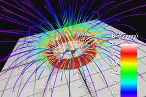
    We can now analyze the magnetic field by measurement of its flux density and visualize it in 3D. For the moment we only scan regions (a plane) and measure the three-dimensional vector (BX | BY | BZ) | of every single measuring point with assigned coordinates (Y X) automatically - and the result is a vector field.

    So far we measured metallic different objects to watch whether you can recognize for example a current-carrying wire formed as a heart, a saw blade and a bullet casing (we found in Berlin after new years eve; it is an empty blanket, don’t worry).

    Coming back to magnetic fields, we can determine the spatial orientation and intensity of the magnetic flux at any given point on a 2d plane (scanner area). As a result, we have a 5D-vector field of the examined magnets, which can be visualized with the aid of mathematics programs such as MATLAB and investigated further.

  • 4. Step: For the Future:

    Myrijam07/10/2016 at 16:03 0 comments

    We didn't have any time yet but for further development we want to extend the scanning device so that the height of the scans can be changed as well by the principle of a delta 3D printer - then we would measure a 6D vector field…

View all 4 project logs

Enjoy this project?

Share

Discussions

J. Ian Lindsay wrote 04/23/2017 at 23:46 point

This is 5-shades of awesome...  I'd like to be able to generate this data from 17 different input sources. It can be assumed that the position and orientation of each sensor (although not constant) is known with a good grip on error. Could your technique be used in conjunction with this sort of input?

  Are you sure? yes | no

Myrijam wrote 07/18/2016 at 20:53 point

Hi and thanks for the suggestions. MatLAB seemed very promising in visualizing vector field plots (we don't even have vectors yet in math) and we liked the idea that you can control I2C-devices like the 3d-mag sensor and motorshields directly from within MatLAB code. We started programming a first scanner routine and found that you couldn't connect multiple I2C-devices (untested so far in the Arduino support). So we did the work around with the Arduino and the smartphone to interface and control the scanner. We got the MatLAB licenses after asking for support straight away...
For the next development steps we plan to do a real 3d-scan and a more sophisticated calibration (spatial as well as measurements are concerned). We might have a look at other visualization tools, too...

  Are you sure? yes | no

Sandeep Kumar wrote 07/17/2016 at 12:25 point

Nice project
How about doing it with python.Its free & open source and should help others participate in your project
as matlab is expensive and closed source.

  Are you sure? yes | no

Trevor Johansen Aase wrote 07/17/2016 at 17:26 point

MatLAB is standard in academia and way more proficient at handling massive amounts of data and doing complex calculations. Once the concept is ironed out time should be spent on making a dedicated open source analysis suite I agree.

  Are you sure? yes | no

Sandeep Kumar wrote 07/17/2016 at 17:40 point

It depends upon what you mean by "standard".
 "and way more proficient at handling massive amounts of data and doing complex calculations" - its not true
how can you say that? have you tried to compare it yourself? its just a belief i guess.

Generally its hard to switch over to another platform once you dive deeper into the project
i recommended python from beginning just for that reason.

Have fun.Its your project. :)


  Are you sure? yes | no

K.C. Lee wrote 07/17/2016 at 18:45 point

There are open source matlab alternatives. e.g. Octave, FreeMat, Scilab etc

Python isn't even an alternative on par with those without a lot of coding.  It is like you asking for people to code everything with bare metal C code and build their own PCB etc when someone is using a eval board and software framework with some libraries to try out something quick.

Remember that the bulk of the project isn't about coding stuff in matlab...

  Are you sure? yes | no

Similar Projects

Does this project spark your interest?

Become a member to follow this project and never miss any updates