 Martin Vincent Bloedorn
CONSIDERATIONS
I live in Brazil. Here - unfortunately - lots of components are expensive or hard to get. This constrained a lot of design choices, a few of which are presented below.
Also, I tried my best to use solely open-source development tools (or, in worst cases, free-of-charge ones).
Documentation
I just finished my thesis on the biohand. The project is thoroughly detailed there, with relevant steps in mechanism synthesis, electronics design, software structure and prototype assembly. Check it out! :)
MECHANICS
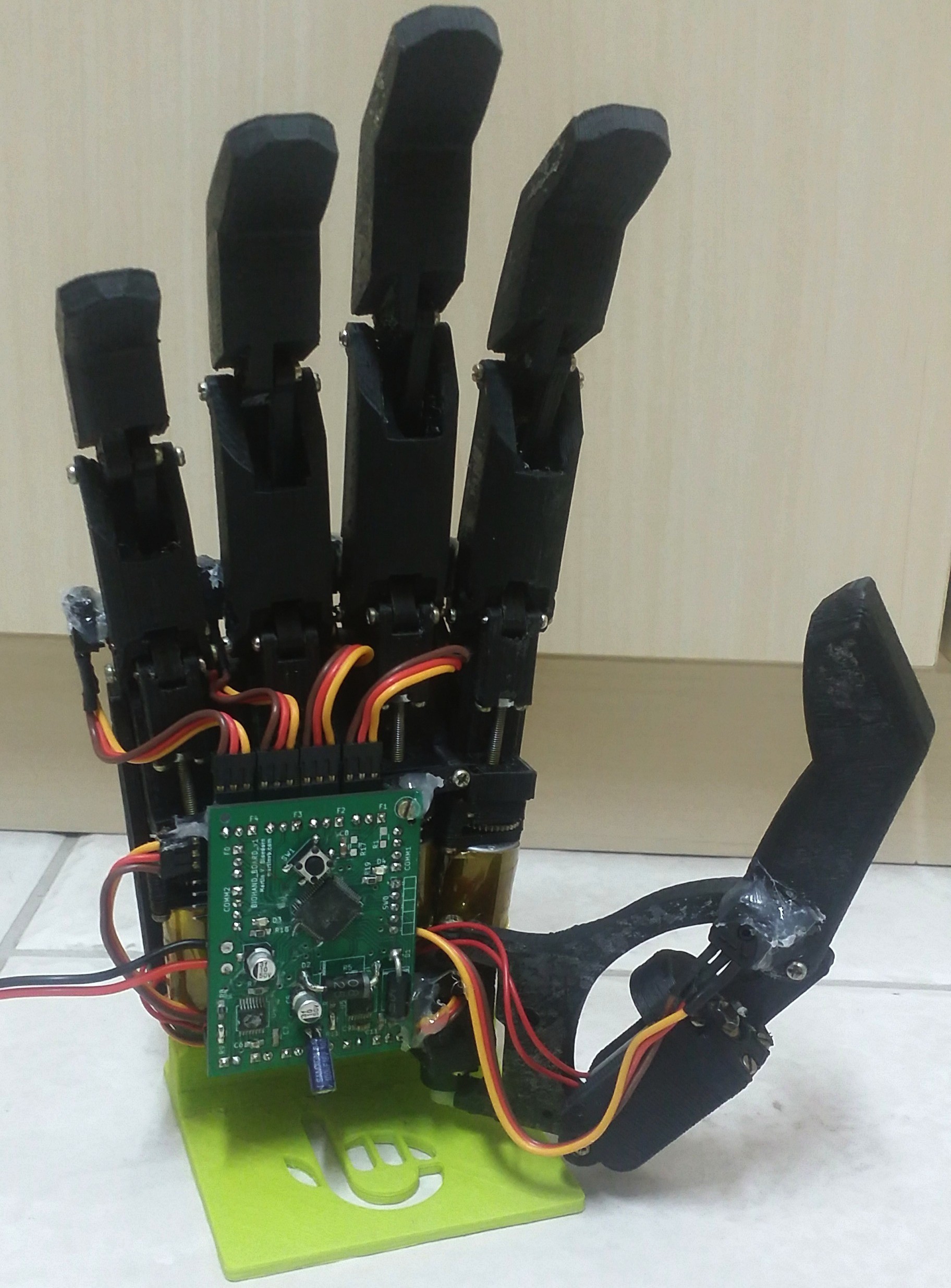
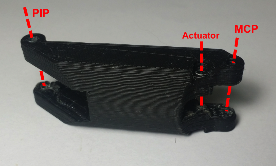
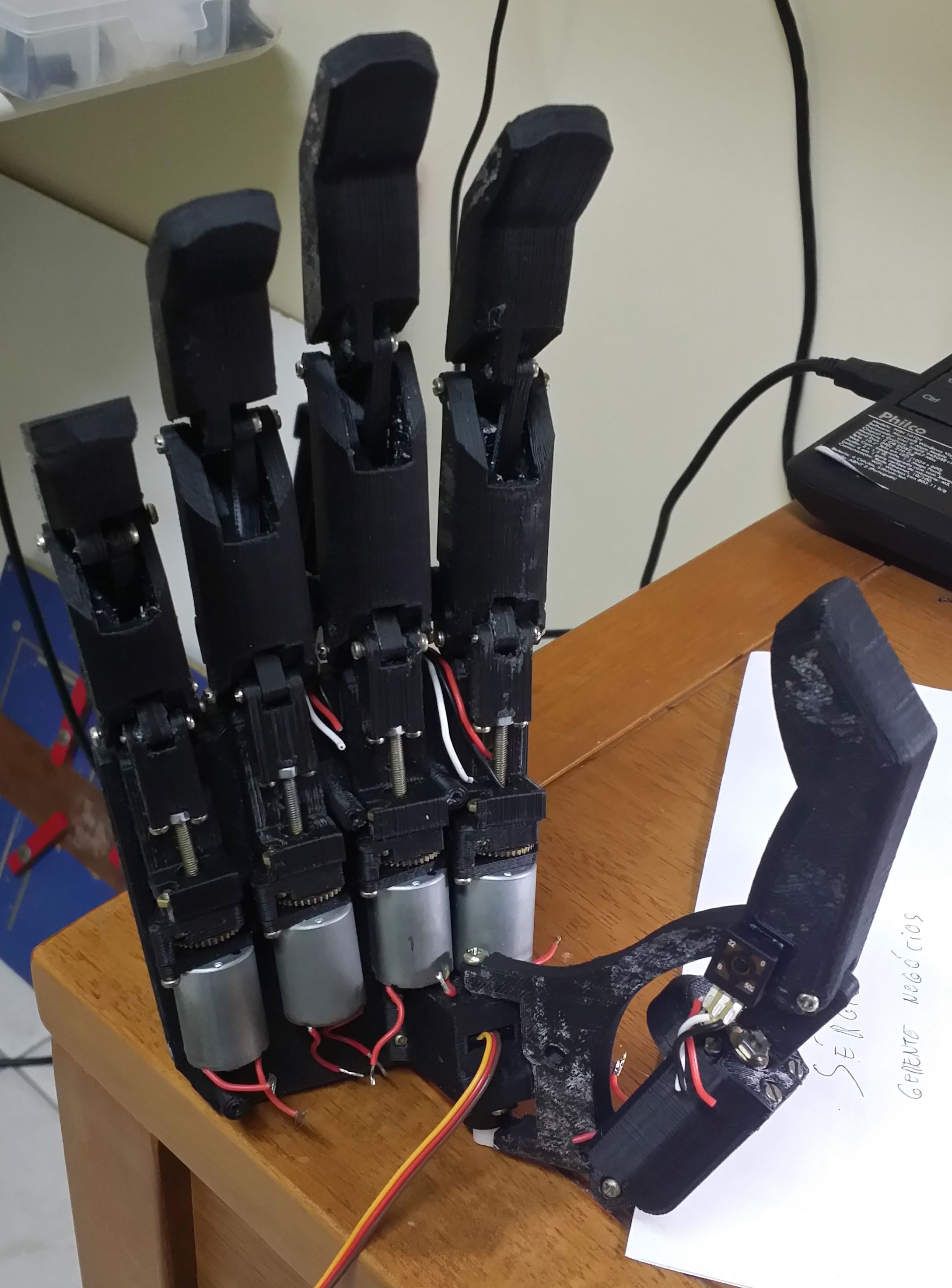
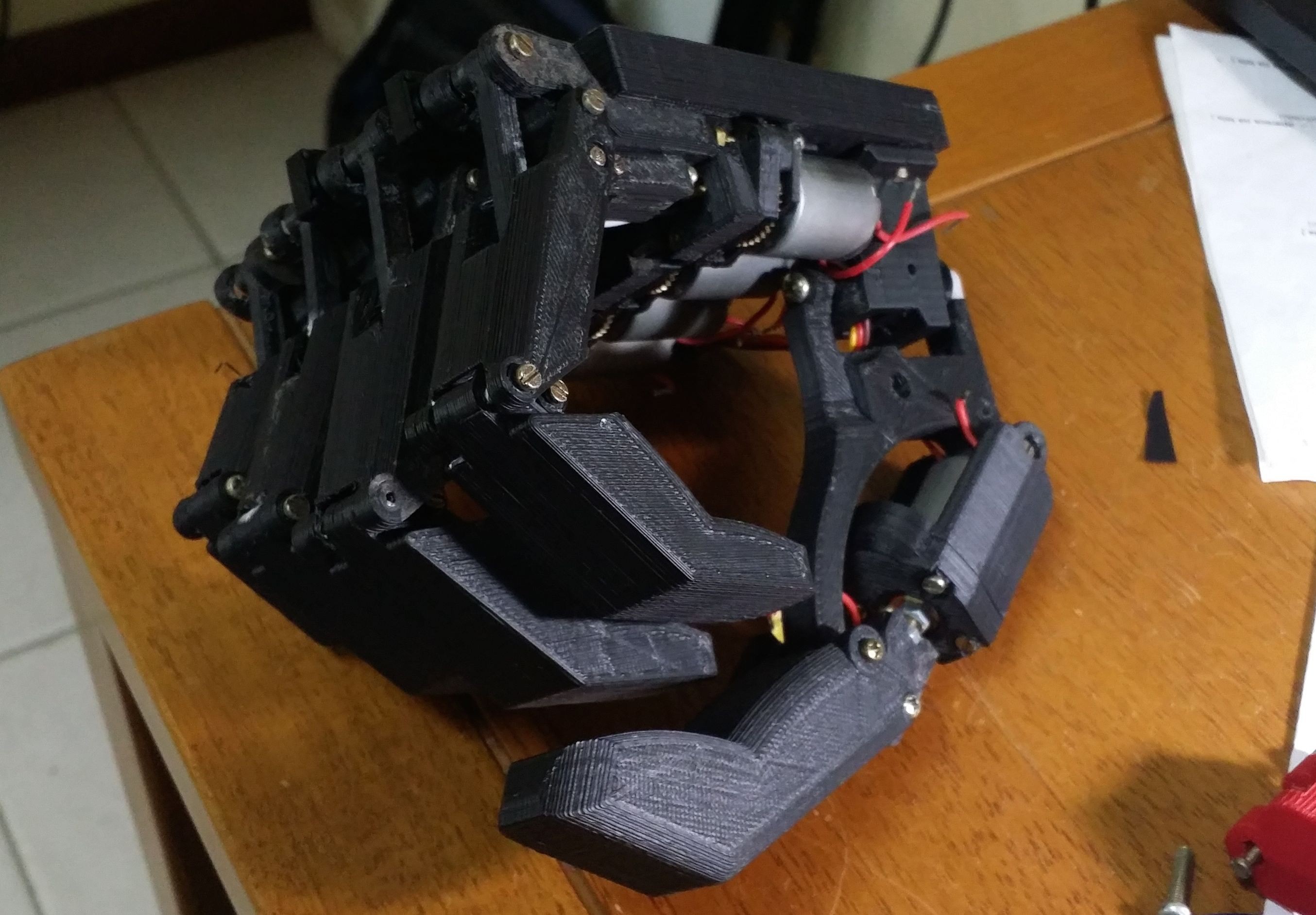
Each finger is actuated individually, and relies on a 4-bar linkage mechanism to synchronize the movement of the proximal and distal phalanges (see picture below). The actuator is fully enclosed in the palm, to guarantee that even patients with wrist disarticulation or transradial amputation can use it.
Lots of thought went in the choice of the actuator itself. 'Proper' DC motors (eg. Maxon or Faulhaber) are generally too expensive for this application; same goes for linear actuators. Chinese DC motors with enough torque and decent reductions are hard to find and may easily be discontinued - a danger for any design.
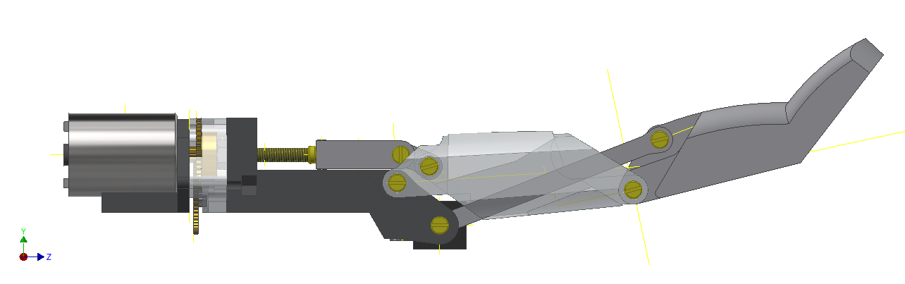
I've noticed that standard RC servos, on the other hand, are available *pretty much* anywhere in the world, and its internals (specially regarding mechanics) are roughly the same across a wide range of manufacturers. With that in mind, I used the DC motor and two gears of a standard metal RC servo to design a 3D printable linear actuator. A standard 25mm M3 screw acts as a leadscrew.
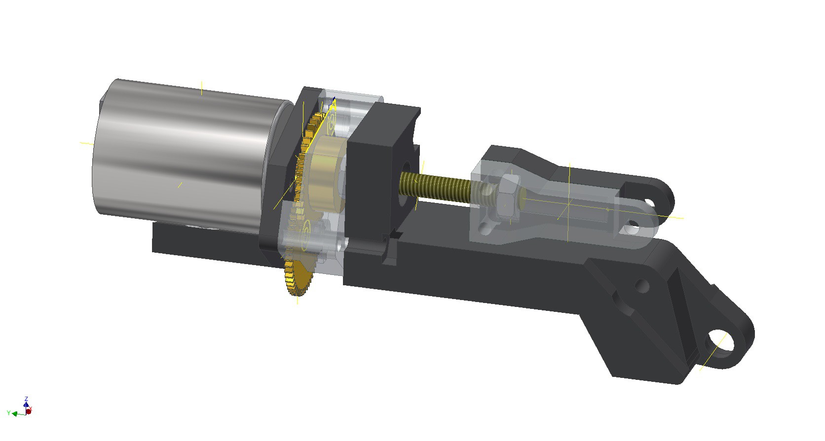
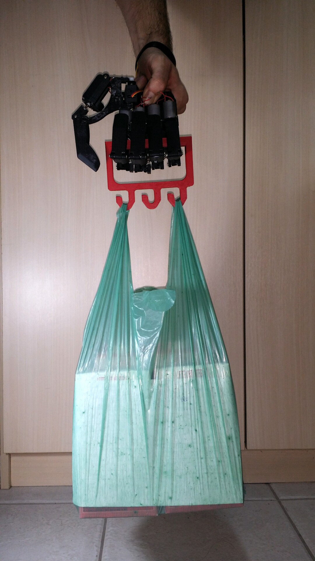
While it looks flimsy, it was able to lift 1kg. On top of that, the servo's potentiometer is used to supply feedback about the finger's position - something hardly available in commercial-grade hand prosthetics. The long screws in the servo's enclosure can also be used as dowels for the joints.
The thumb, uses a common arrangement with 2 degrees of freedom, with a linear actuator moving the first metacarpal joint, and a micro-servo driving a rotary motion for the carpometacarpal joint.
Lastly, I designed all the finger's parts in such a way that they're printable laying flat on the printbed. The part's orientation during print is of great relevance in its final strength. With this setup, the assembled finger mechanism was able to individually hold 2kg in a non-destructive test.
The prototype still doesn't feature aesthetic covers (yet to come!), and it's being assembled.
The mechanical designs were made using Autodesk Inventor. While the program isn't open-source, 3-year Pro licenses are supplied for students. I'm considering moving to Onshape in a (somewhat not so) distant future.
ELECTRONICS
I'll be driving the whole system off of a 2S LiPo battery. The thumb's micro servo is getting a proper regulator (an LM317 or an LM1117). The DC motors are being driven with TI's DRV8801: 2A RMS current output (for real! Heard that, L298?), internal logic and an amplifier for sense current made it an easy pick.
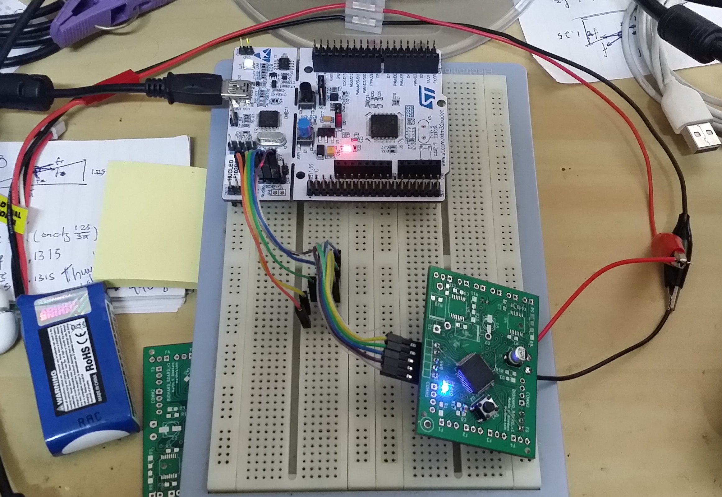
For the processor/controller, I went with an STM32F103 ARM Cortex M3. I was already familiar with the processor, and ST's recent lineup of Discovery and Nucleo boards are a significant step for lowering the entry price for ARM development. I'm currently using an Nucleo-F103RB both as dev-board and SWD probe.
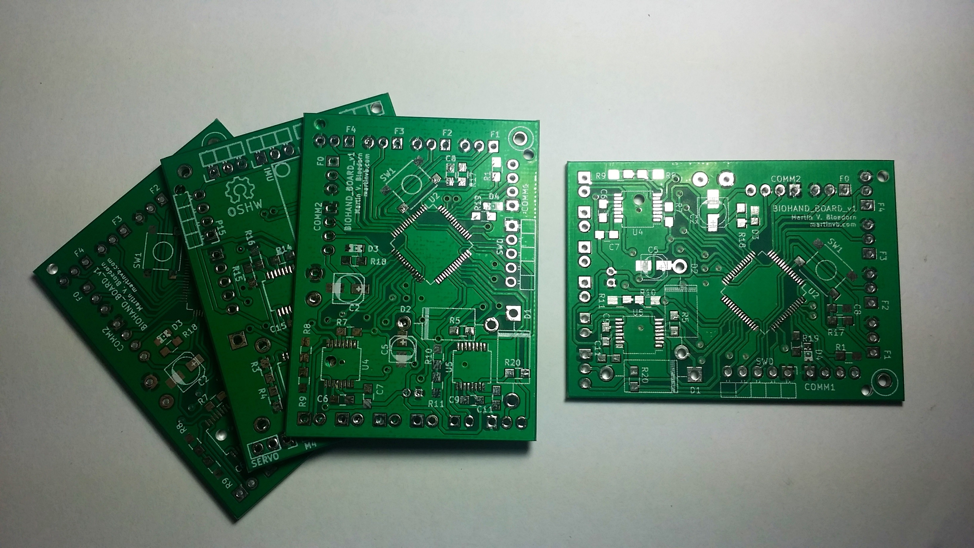
Electronics are still in its early stages. For now, I hooked up an STM32 (on a breakout board) to the SWD probe [left of the pic], and designed/milled a carrier board for the DRV8801 [right].
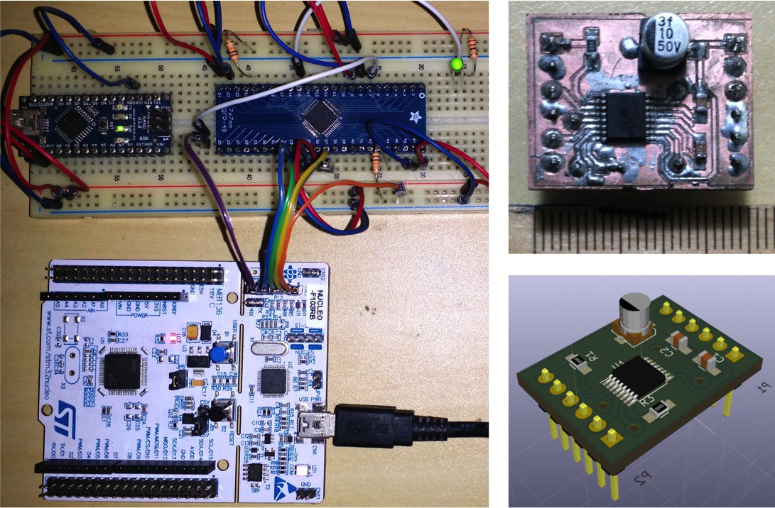
The complete board is still being designed under KiCad.
SOFTWARE
Toolchains for embedded ARM development used to cost a kidney (or be insanely hard to use). In the last years, however, many great open-source tools have become available. I'm currently using a software setup that consists of:
- A GNU toolchain for embedded ARM,
- OpenOCD for programming/debugging the target IC,
- Eclipse CDT as DE.
Since the hardware is still being actively developed, I've had little time to address proper software development. For now, I've assembled a software template that...
Read more »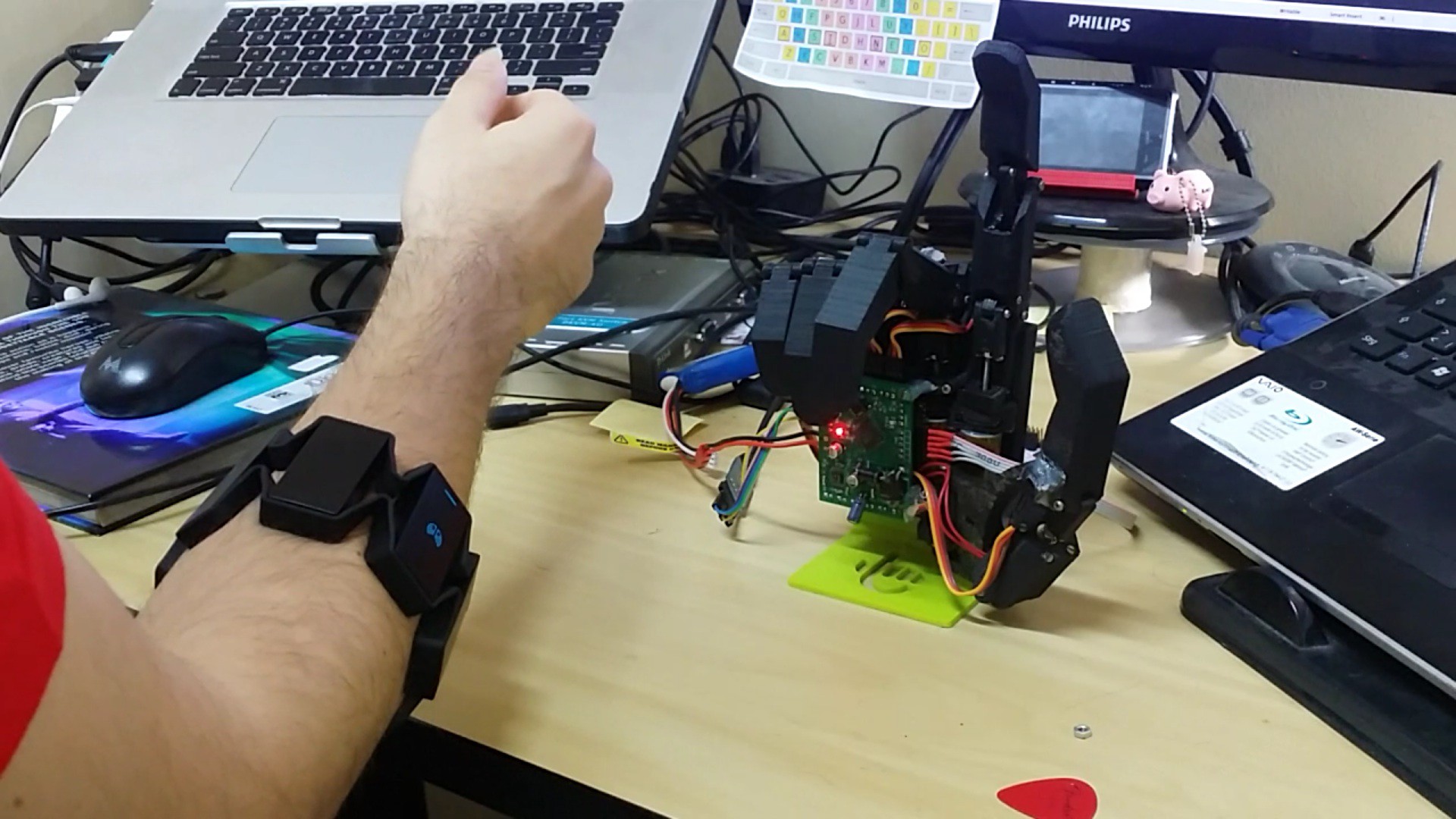


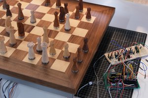
 Phantom Chessboard
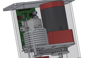
 patchartrand
 ravi butani
 nerd.king
Do you think it would be interesting/feasible to do torque control on the joints ? (Since you are already using DC motors and not pre-made servos, the electronic would be simple)