 pj
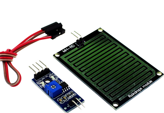
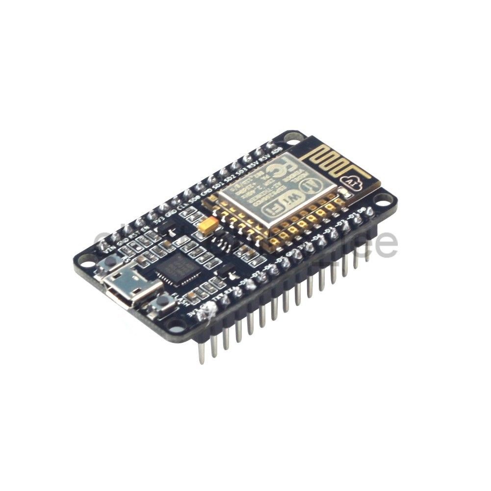
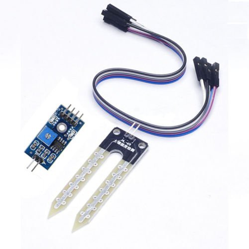
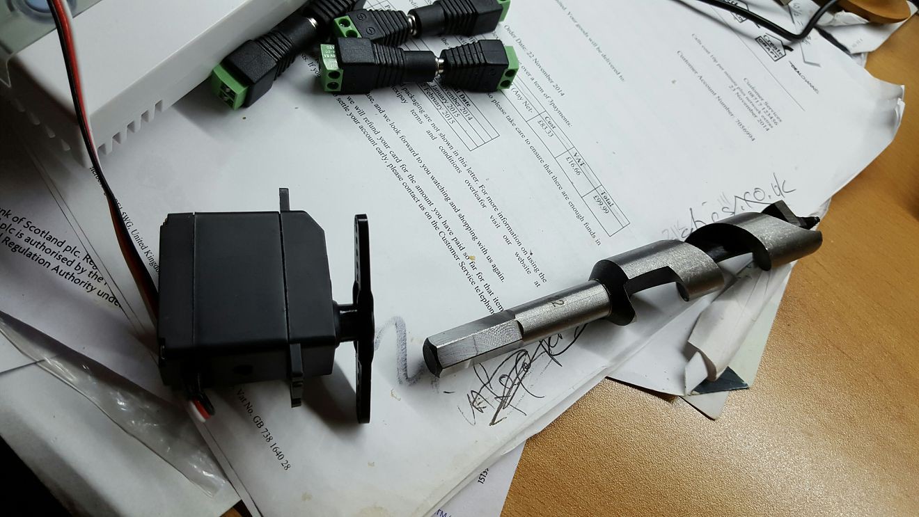
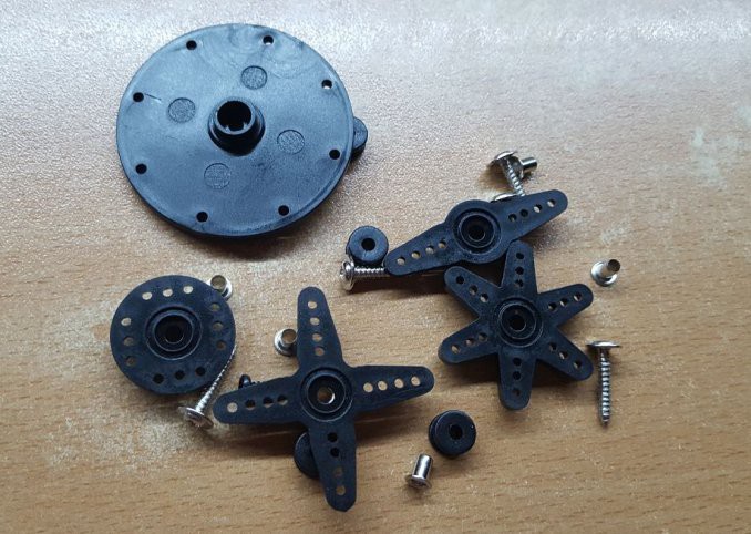
pj- I have bought all (or most) of the hardware now. The software will be python on an odroid sbc perhaps or something small for under the stairs) and arduino sketches on my arduino megas and/or nodemcus. I have at least one of all the components I need, like water level sensors, flow sensors, temperature modules, relays etc. (See picture) I have three tanks one of which will be the sump filter tank.
- The whole aim for this project is that I am away from home for different periods of time on occasion and I didn't want to rely on my flat mate to feed my fish and clean the filters, water the plants etc.
- I have been reading up on Aquaponics and am really interested. I would like to incorporate some sort of plant bed into my system. I am not a herb lover but i like the idea of fresh spinach (the all year growing type).
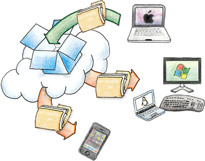
- I am going to use the IoT (Internet of Things) ethos. I have setup an MQTT {IoT} server on my raspberry pi and have got the arduinos (and NodeMCU units) to talk to each other (!). This is to make everything nice and easy for all the messages and decisions. ( I want to incorporate at a later stage my home devices: curtain closers, light switches etc and my Basic Burglar Alarm system: door status devices, alarm bells, strobes etc)
0%
0%
Aquarium controller / home automation
I am building an automated aquarium controller to fit into my home automation system.
Become a Hackaday.io member
Already have an account? Log in.
Just one more thing
To make the experience fit your profile, pick a username and tell us what interests you.
Pick an awesome username
hackaday.io/
Your profile's URL: hackaday.io/username. Max 25 alphanumeric characters.
Pick a few interests
Projects that share your interests
People that share your interests


 WJCarpenter
 mircemk
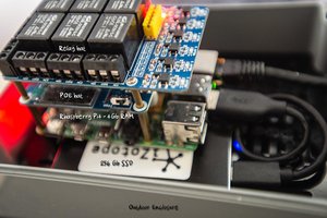
 6toecat
Certainly! It sounds like you have a comprehensive home automation project in mind, with a focus on creating an automated watering system for both indoor and outdoor plants. Here's a breakdown of what you have and what you're planning to do :
Hardware Components:
One Raspberry Pi or similar (e.g., Odroid)
Two Arduino Megas
Four NodeMCUs
A variety of relays, monitors, pumps, thermostats, flow controls, actuators, etc.
IoT Integration:
You plan to connect your Arduinos and NodeMCUs to the Raspberry Pi or Odroid using the Internet of Things (IoT) ethos. This means you want these devices to communicate with each other and possibly allow remote control via the internet.
Use Case:
Your primary goal is to create an automated watering system.
This system will cover both indoor and outdoor plants.
You intend to integrate this system into your existing home automation setup.
Infrastructure:
You've mentioned having 2 kilometers of copper cable already installed in your home walls, which was done during a rewiring process. This infrastructure could potentially be used for wiring your automation components.