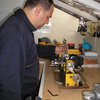
 Jay Doscher
The concept is not a new one, but rather an existing idea using a novel approach. Solar panels generate much less power when the sun is "off axis" and at an angle to the panels. By pointing the panel at the sun, we get the best power for the given panel. Depending on where you are and how long you have line of sight to the sun, you have a much longer period of power generation, especially during morning and late afternoon hours.
You can find even more photos and some additional details on my blog here.
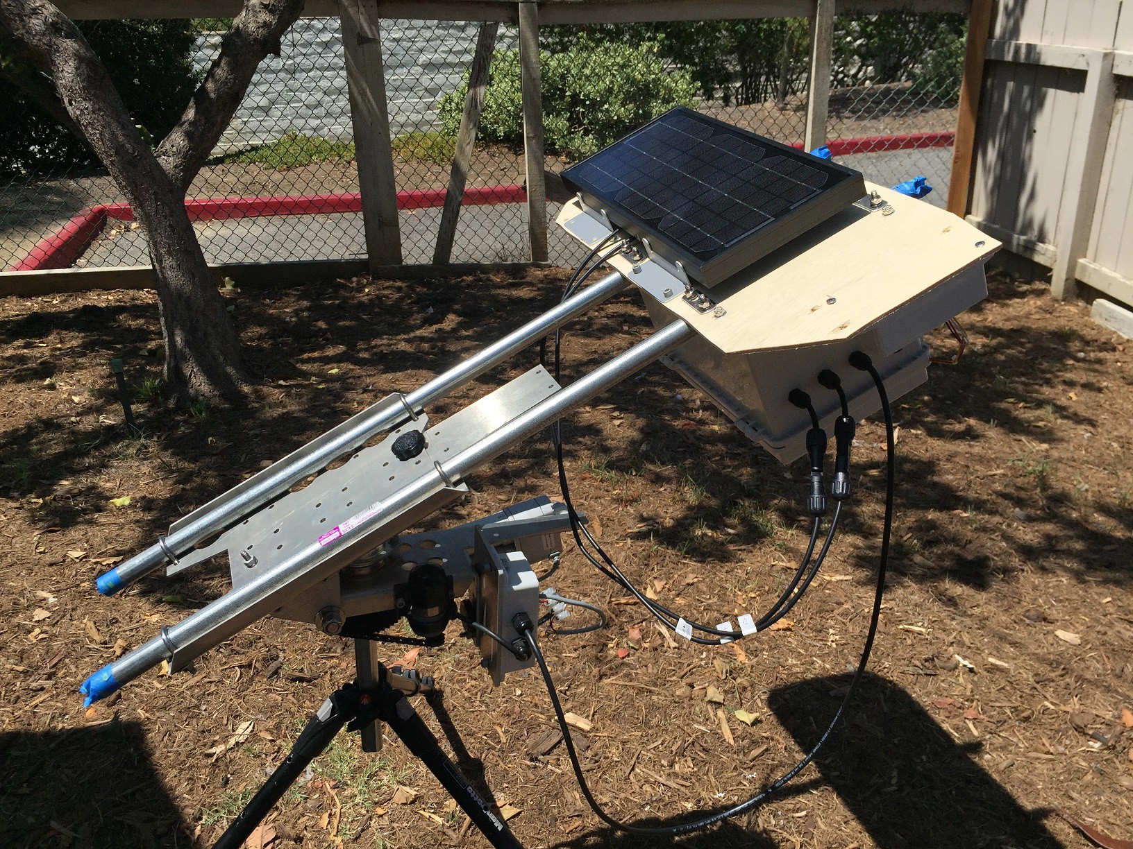
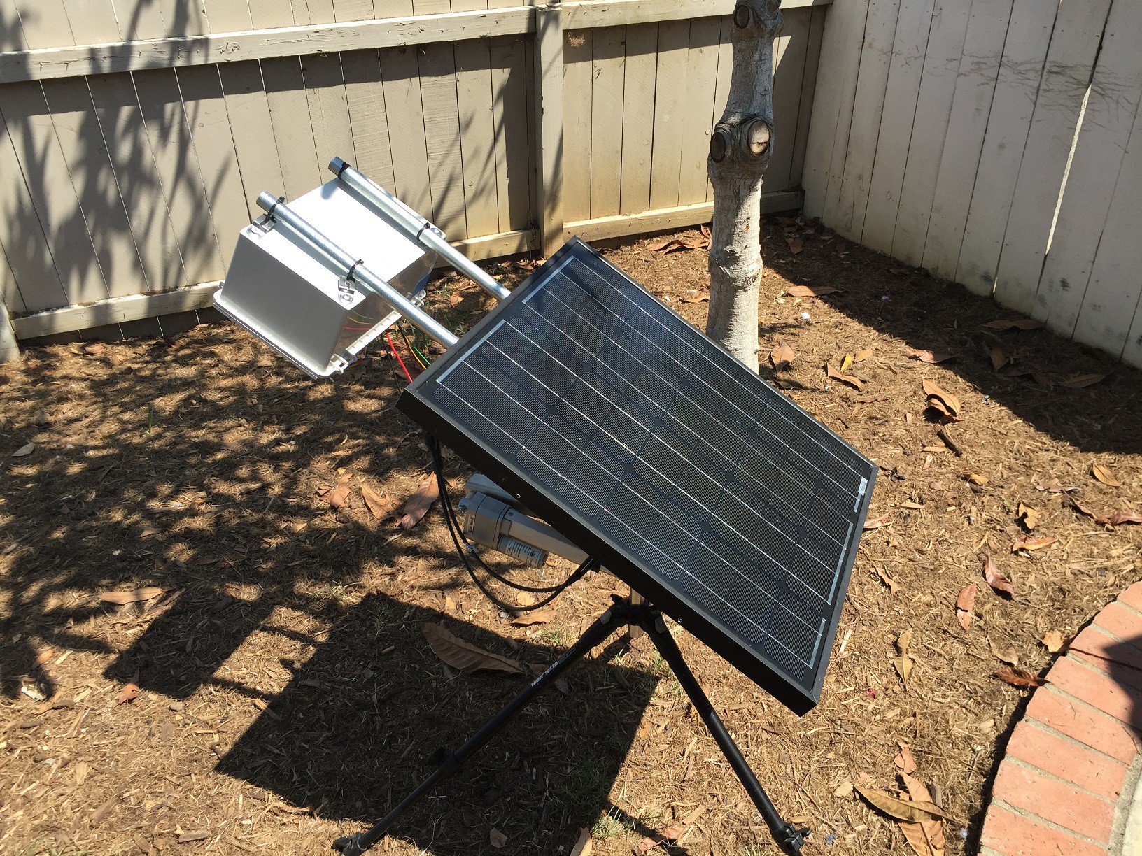
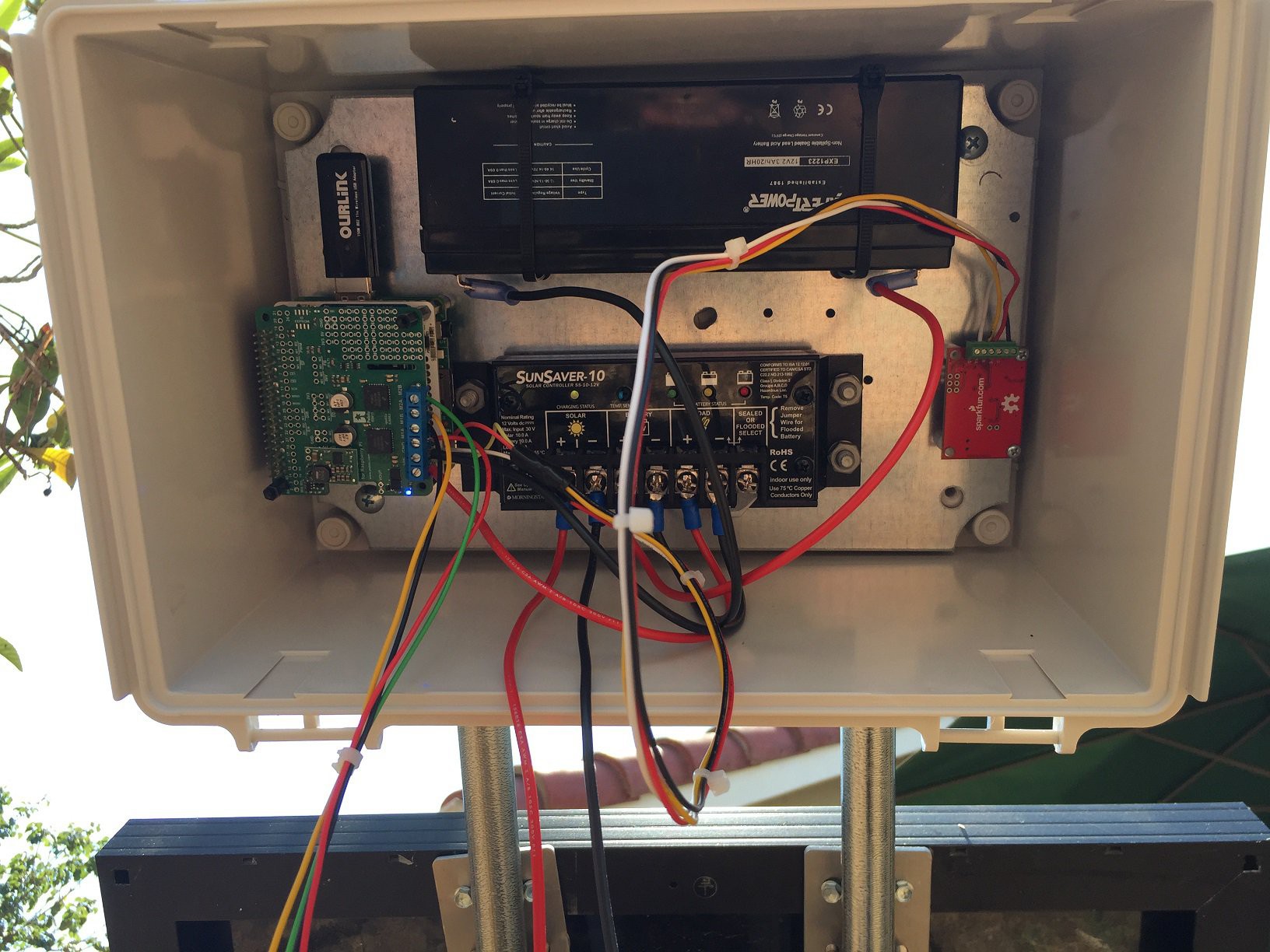
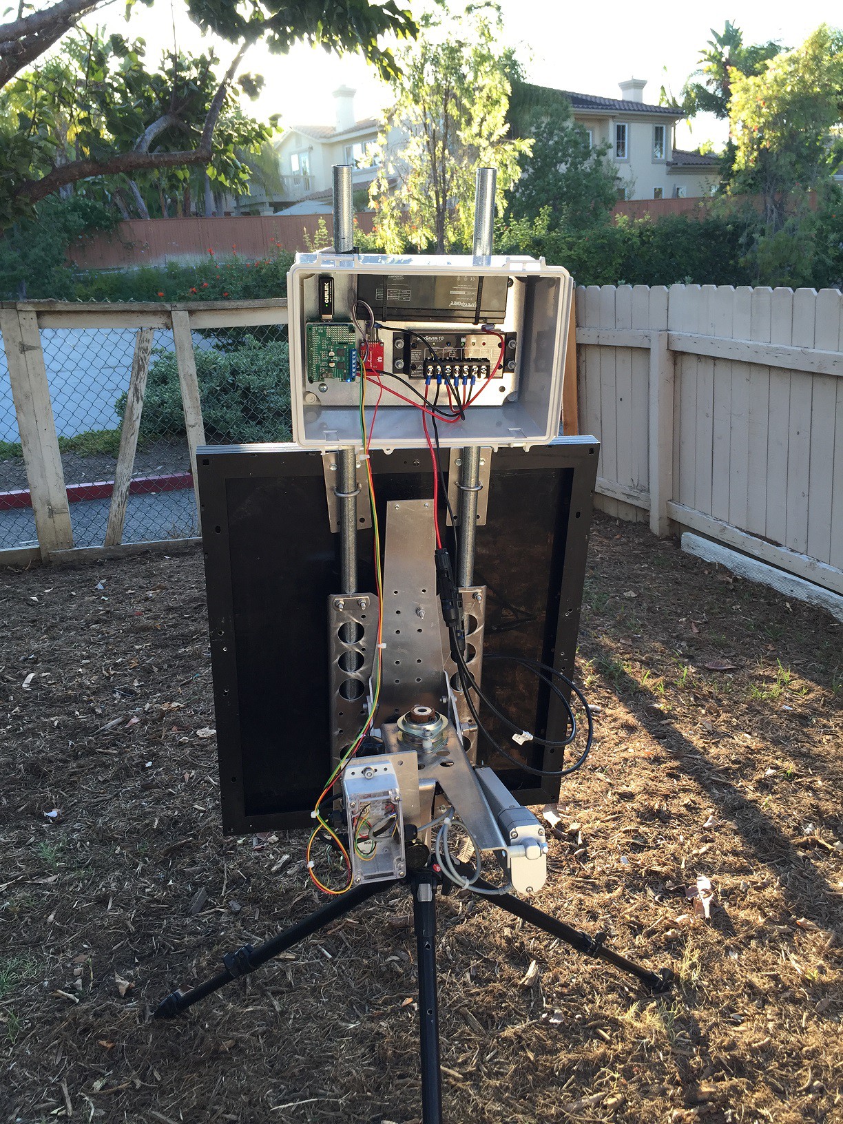
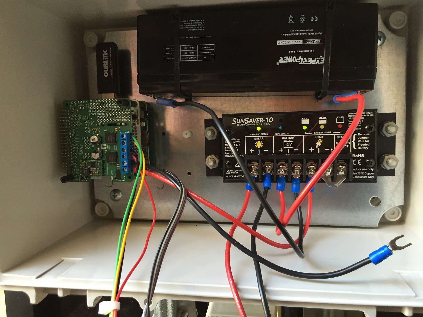
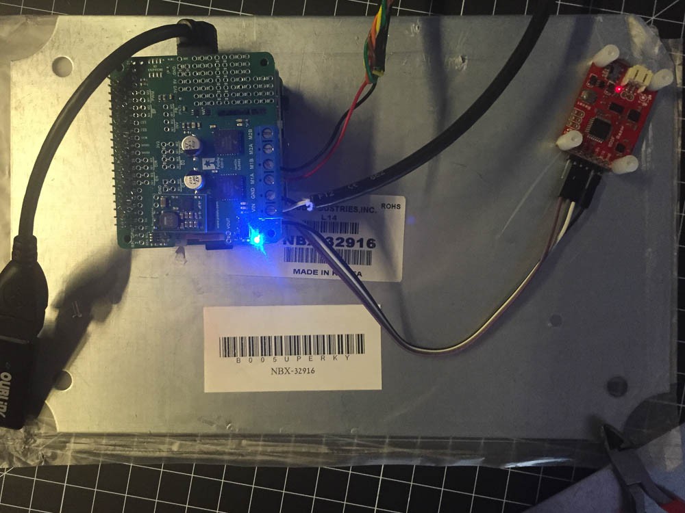
This project does this by using pre-programmed GPS coordinates to calculate the sun's position. This is done via the Open Source Python library Pysolar. By using a simple web interface, the device can be programmed to reliably predict the location of the sun without anomalies that usually come from optical or GPS receivers. With a Raspberry Pi, IMU and high current motor controller, we can easily move a 30 lb. panel. The entire setup is designed to break down as needed and fit in the trunk of a car, but also weatherproof enough to spend all year outdoors.
The Solar Robot 7 project can be divided up into the following categories:
- Open hardware design of circuits and mechanical components
- Open Source publishing of underlying design components
- Optimization for cost
- Optimization for reliability
- Enabling use of the project by non-profit organizations and Makers
The project in itself works, and works well. It's been in development for 2 years as a hobby, and I think this is a great time to share it with other Makers. The idea is simple, to collaborate and simplify the design, make it cheaper and easier to deploy for developing countries and enthusiasts alike.
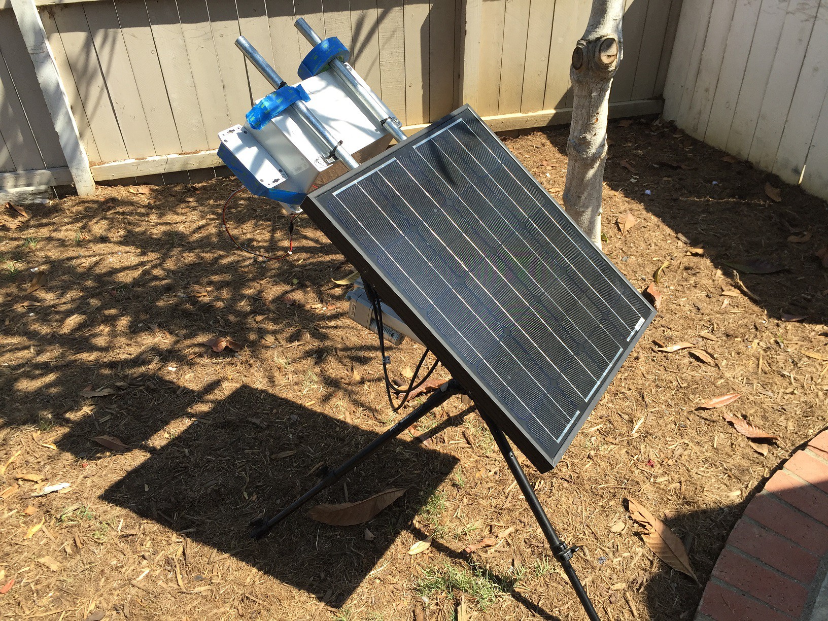
The project has a working prototype, but it is still bulky and very expensive. I am working to reduce the parts and overall cost of the project.
All of the sheet metal components were cut on a waterjet using Big Blue Saw's service- the current design has many parts that have been bent at a machine shop, but the cost of that doesn't scale vs. Big Blue Saw's method for parts that can be bolted together. That's another optimization that is in process.


 Uncle Toby and Aquaman
 Giovanni
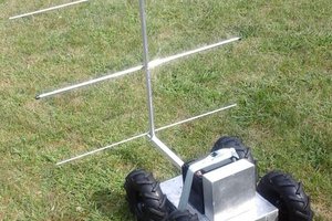
 Glenn Powers
 eelco.rouw
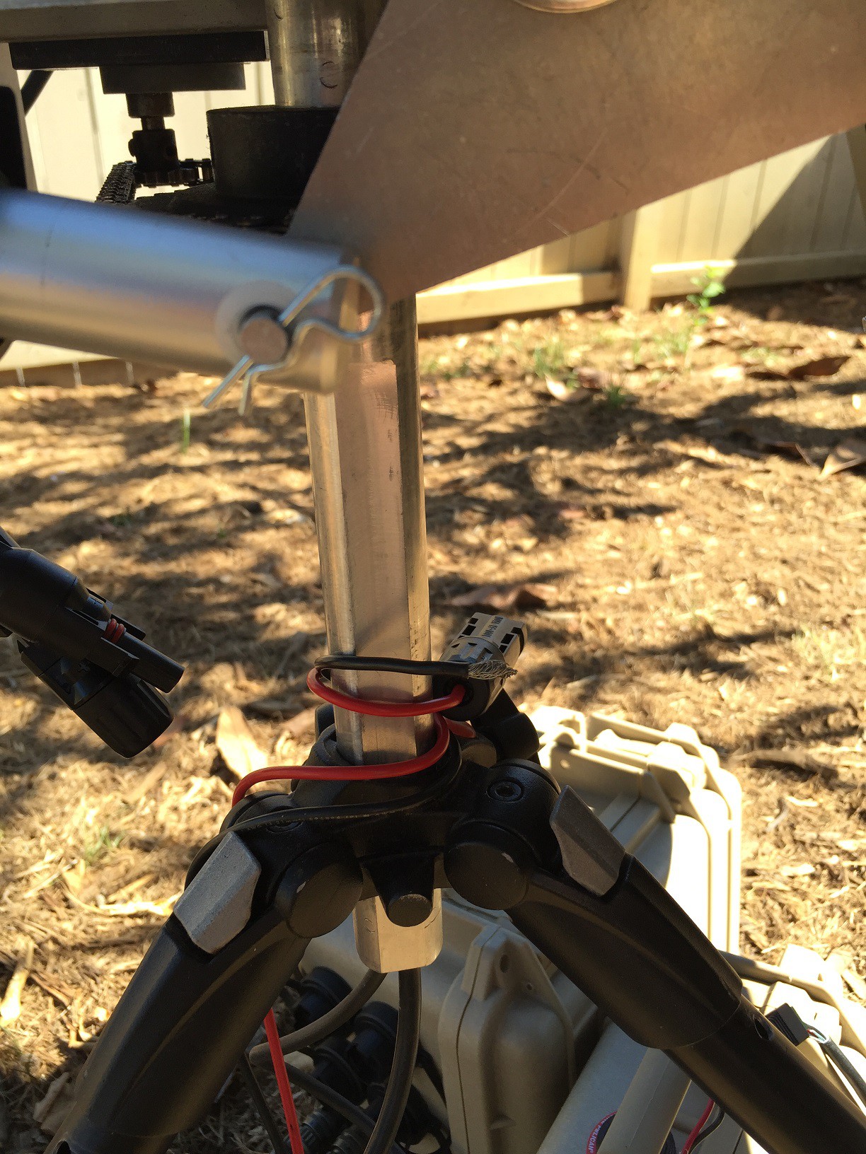
Are the details on the bearing for where the vertical pole and horizontal plate meet available? Also would like information on the motor used with the chain and sprocket (azimuth positioning) if possible. Thanks.