Craig Hissett
-
Time for another bash?
05/21/2021 at 23:34 • 0 commentsTimes have changed, thanks to certain viruses and the pandemic they caused, and I find myself needing a go-to setup for tinkering at home.
I want to throw the following together:
- Pi with official touchscreen (in a smartipi case) armed with a cluster hat and a USB Hub
- Network switch
- Arduino Uno w/chip flashing Shield
- Two Arduino Megas (both with display shields, one also with ethernet shield).
This setup should give me more than enough scope to develop and prototype the projects I am working on now.
The Pi will be the heart of this, with all the development environments required for Arduino, python and .NET Core development.
The cluster hat opens the door to using Pi Zeros for modular expansion utilising the usb gadget modes.
The switch, and Arduino with the ethernet shield, will allow for network based prototyping (useful for some OSC applications I am working on)
The second Arduino mega can be used for serial Comms, and also connected to the other mega via I2c, for example.
The Uno is not required, but set up for convenience, really. This will make it easy to flash ATMega328 chips for projects once tested on this setup.
Finally the addition of another WiFi dongle will allow for the Pi to connect to my home WiFi and share that connection via the ethernet port to the switch.
No idea how best to put all this together at the minute. First thoughts are to mount all to standoffs on a board that fits in a box I have.
-
Project Revisit?
04/14/2020 at 09:29 • 0 commentsAlthough I discontinued this specific project as such, the plan to have a decent, portable development platform is still there.
Having recently picking up the Totem Mini Lab for a review the platform has reignited the spark to come up with something including a Pi.
I am going to build a similar lab-style frame and include a Pi, touchscreen, Arduino Mega and a few other things to use for development.
I will document my progress here where I can.
-
Project Discontinued: Change of Direction
12/07/2016 at 13:08 • 0 commentsI will no longer be working on this project as such.
I'm really happy with how this ended up; It worked a treat for the core functions of what I needed it to do in terms of a platform I could prototype ideas on.
It still had a long way to go to refine features and also tidy cable management and take it to a level where it looked and functioned like I wanted.
I have recently bought one of the official Pi Touchscreens, along with a Raspberry Pi 3. I am aiming to turn this into the programming platform I've needed for so long :-)
As far as doing this I want to design an enclosure for my Arduino Mega with a the lcd shield attached. This case will feature a tiny breadboard and expose the analog and end digital pins on the Mega.
The combination of the breadboard and available pins will give me a great prototyping 'extension' to my touchscreen setup, and the inclusion of the LDC shield with buttons will allow plenty of options for communicating with the Pi via the serial connection. In future I may expand this to include either an EPS8266 module or a bluetooth module to provide further communication options.
Once I've given this more though I'll most likely start a new project.
Cheers!
-
Coming Soon
09/25/2016 at 01:06 • 0 commentsHopefully in the next week or so I will have some more information to share on this project.
The screen is in, the boards are mounted... Just need to iron out a few little issues and it will be working!
-
Power issue resolved!!
07/20/2016 at 21:52 • 0 commentsToday is a good day!
I revisited my dodgy power module and this project as I wasn't satisfied the moduse was the problem. Sure enough, it was working fine.
I checked out the driver board for my lcd screen and metered out some of the tracks. I found a few traces that wevent up to scratch, plus a burnt out component. Bypassing the traces withe a bit of wire and replacing the burns parts and voila - it works!
I just need an extremely short HDMI cable and this little fella is usable!
-
Powering the Device
04/12/2016 at 15:00 • 1 commentNow that I have found a bit of momentum I am keen to keep it going, so I am just doing a quick post to cover a little progress.
Needing 12v for the screen and 5v for the Pi and arduino and any other devices I may connect in future, I have always wondered the best way to power everything from one input; is it best to pump 12v in and step down for the 5v devices or vice versa?
Anyhow I was digging through my bits and bobs and I found something ideal for this (see picture below). A variable power module.
I ordered two of these little beasties from Ebay many moons ago. They were cheap; and it turns out thy were cheap because they were in kit form. Lacking confidence in soldering so many parts in (read: lazy) I ended up not using them. They've come in handy now!
The boards themselves have a barrel jack or screw terminals for 12v in, and then has a series of screw terminals on board; a set for 12v out, a set for 5v out, and one set for a variable voltage, adjustable onboard using a tiny flathead screwdriver.
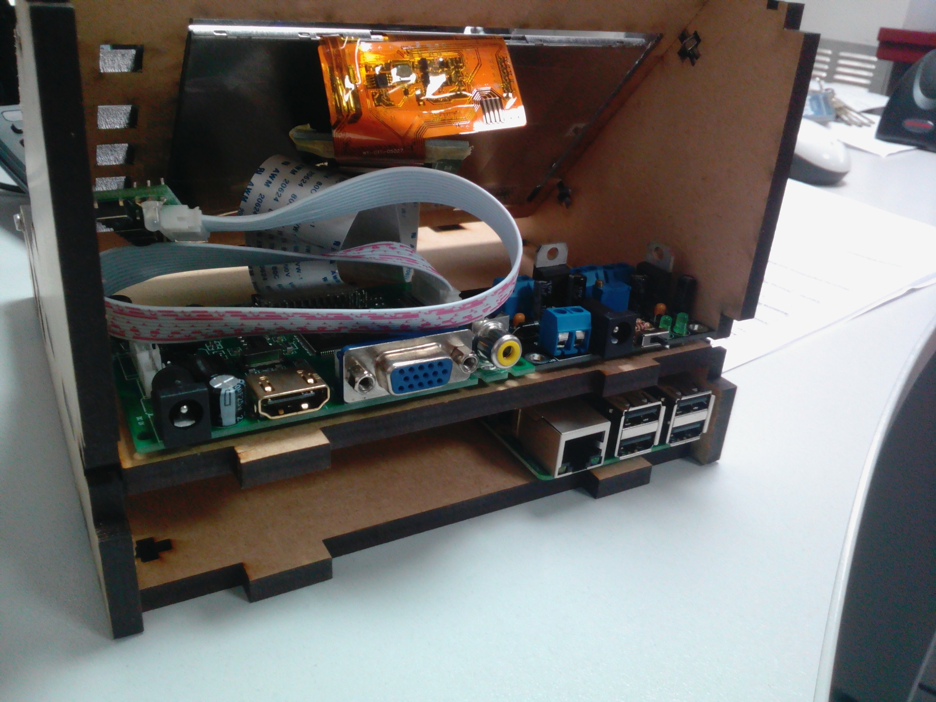
Picture (from a new angle for @Stefan Lochbrunner's enjoyment :-) ):
![]()
The above picture shows The Pi (Just a B+ for now) on the lower level, and the screen driver on the top deck, and to the right of it, my power module.
Over the next few days I will hopefully get this wired together, but first i need to get the screw holes and tabs adjusted so the case all fits together nicely, then create a frame/bezel for the screen to make it fit the hole better, and adjust the holes to the side of the screen so the screen driver buttons can be accessed.
-
Update: Long overdue!!
04/07/2016 at 01:30 • 0 commentsAfter a period away from projects I am finally winning my battle to create time to work on them again. Not a lot of time, but a little is better than none at all!
After a long, protracted affair I finally managed to get Jinx's splendid 3D Google Sketchup files converted to 2D Illustrator files, and get it laser cut in trusty 6mm MDF.
Converting the files using some free software ended up being the solution, but it has come at a small cost; some of the screw holes don't align, one of the tabs on the back panel does not fit, and the screen hole is too bloody big.
Not to worry though; screw holes can be drilled and tabs can be filed. I have also retained the piece of MDF from the screen hole, so I will create a nice little frame from it to fill the space and make the screen fit!
-
Google Sketchup into Adobe Illustrator - HELP!
11/28/2015 at 01:20 • 0 commentsThis project has hit a snag, and I'm hoping someone can help.
The workstation is all designed, and s ready to be lasercut - problem is, it is designed as a 3D model in Google Sketchup but to get it cut need it to be transferred into an Adobe illustrator template.
While I have al the files (Sketchup file, the stls of the parts and the Illustrator template) I do not have access to either piece of software at the moment.
Could anyone help me out?
Thanks!
-
Update: 5/11/15
11/06/2015 at 01:55 • 0 commentsGteat news - I am very close to having my enclosure cut ready for assembly!
Jinx has sent me the stl files and also the Google Sketchup file for his wonderful 3D enclosure, and have also managed to strike a deal with a department at work with a Laser cutter to cut my enclosure for free provided i supply materials (i have also sourced some free 6mm MDF, heh heh).
Unfortunately they use Adobe Illustrator with their machines, so my files were completely useless to them. Luckily I have found a colleague who has kindly offered his services to take my stl files and populate the Illustrator template.
Provided everytjing goes to plan I may well be ready to assemble this project very, very soon!
I honestly cant wait to get this thing up and running; once I have this to write and test code on I will be able to progress with many of my other Pi-based projects!
Sweet potatoes!
-
Design Update
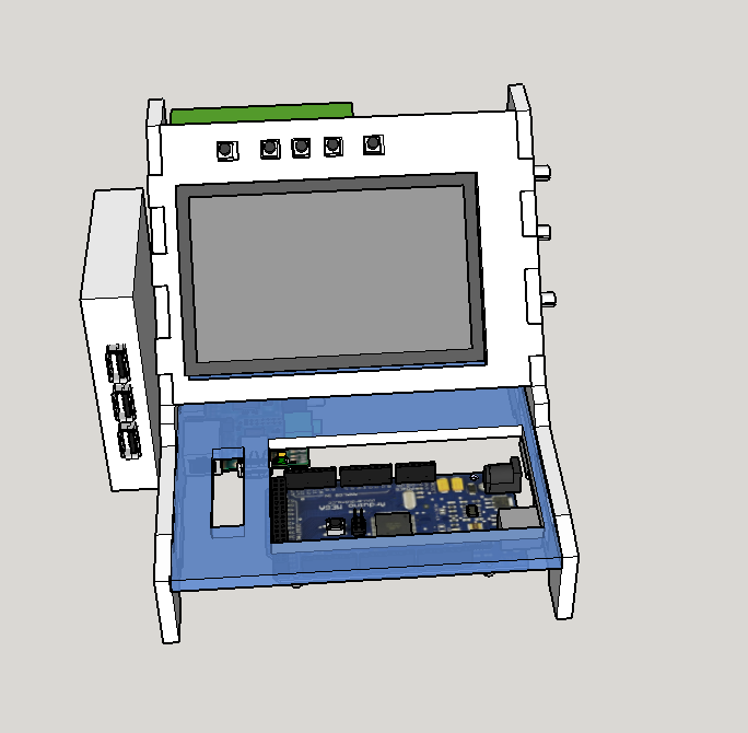
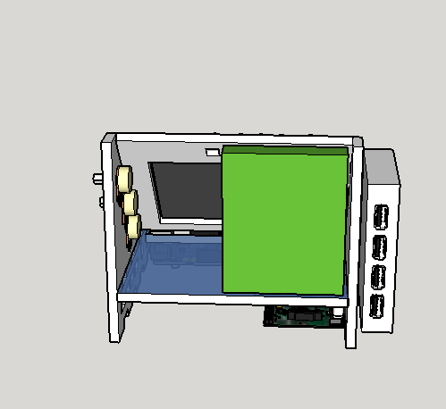
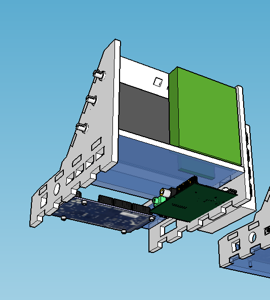
10/26/2015 at 13:47 • 0 commentsJust had an update from Jinx, the chap helping me design my case:
![]()
![]()
![]()
I'm loving the new, smaller streamlined version!
Pi/Arduino Prototyping
An all-in-one development platform featuring a Raspberry Pi, an Arduino, a HDMI display screen and a breadboard area.