 jaromir.sukuba
So, now I'm assuming you have working hardware and set-up software to build the firmware for micro progmeter.
Because progmater doesn't have dedicated programming header (due to space constraints), solder extension wires for programmer lines (GND, VDD, MCLR, PGD, PGC), as I did it here
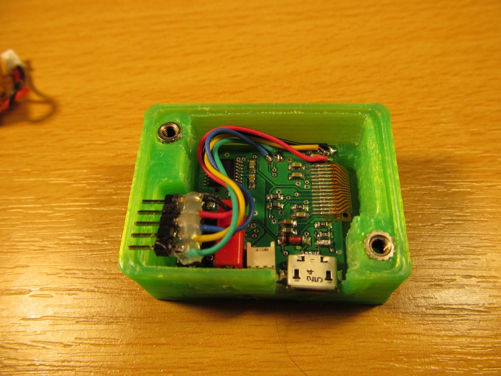
You may solder it temporarily, just for sake of programming the PIC micro, or leave it permanently for firmware updates.
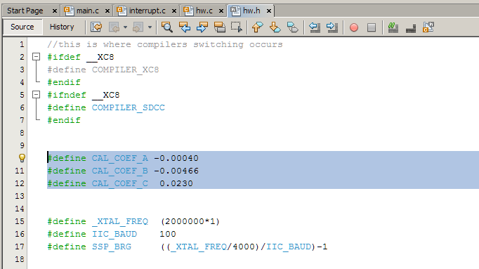
Locate file hw.h and look for coefficients CAL_COEF_A, CAL_COEF_B and CAL_COEF_C. Those are coefficients of quadratic equation used to correct not very initially accurate, but hopefully stable and repeatable voltmeter part of micro progmeter.
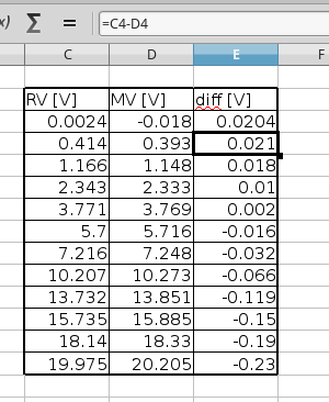
Set all coefficients to 0.0, so no correction occurs and device displays raw measured value. Connect micro progmeter to laboratory power supply, increase voltage and check with ecternal voltmeter, ideally something better than cheap 3,5 digit DMM. You may find out that zero has some offset and higher voltage do have increasing measurement error. Take a dozen of values (the more the better, but there is no point having more than two dozens of them) between 0 and 20V, put into your favorite spreadsheet editor and it may look like this
First column is real value, followed by measured value and voltage difference. This is the difference we need to cancel out.
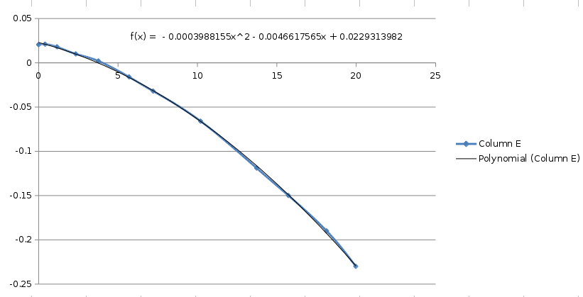
Insert a chart of difference versus real value and add quadratic approximation of it (in Excel or similar - left click on graph, add trend line, polynomial, 2nd order, show in graph). You may need to adjust text formatting to show more decimal places of quadratic coefficients - and there you have it, CAL_COEF_A, CAL_COEF_B and CAL_COEF_C.
If you don't have adjustable laboratory power supply, you may use various power sources around, like 0V (shorted input terminals), 1,5V (AA battery), 4V (Li-Ion), 5V (USB), 9V (6F22 battery), 12V (power supplies to various electronics or car battery, more like 14V) and 19V (laptop power supply) to perform the calibration. Always calibrate against another good voltmeter!
For my calibration I used UT-61E DMM along with Matrix MPS-3003D (generic chinese shit sold under different labels) power supply. Both cheap, but sufficient for me.
Finding out calibration coefficients via Excel isn't the most elegant solution, but simple, accessible and good enough for one-off task. You may use anything, from Matlab to manual calculation via least squares method, depending on your creativity and skill.
Discussions
Become a Hackaday.io Member
Create an account to leave a comment. Already have an account? Log In.
You can do regression analysis in Excel under menu Tools/Data analysis and select "Regression" without plotting a graph. It gives a bit more than just the coefficients.
If you don't see it, you can enable that in the tools/Add-Ins menu: enable "Analysis ToolPak" It may ask you for installation media etc. At least that's how things works in old Ecel before those ribbon menu hiding the useful stuff.
https://hackaday.io/project/4993-dual-channel-battery-chargeranalyzer/log/26034-calibration-lets-all-calibrate-and-have-a-good-time
Are you sure? yes | no
Oh, thank you. Honestly, I didn't know about this one, what doesn't come as too much of surprise, I'm rather poor Excel user.
Are you sure? yes | no