 Kevin
KevinBACKGROUND
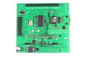
I have worked with a number of microprocessors and microcontrollers over the years. My current interest lies with AVR microcontrollers from ATMEL. I have a development system consisting of a motherboard and plug-in boards that hold the AVR, and other peripherals. I wrote and compiled programs for my AVR parts on a Raspberry Pi. I used a usbtiny connected to the Pi to program AVR parts plugged in to the CPU board of my AVR development system. This worked great until one day the usbtiny stopped working. I have an idea about what happened.
My Raspberry Pi and my AVR development system are powered from different sources. When I was writing code to interface with some hardware I often left the usbtiny connected between the Pi and the development system. Powering the development system without power to the Pi (or vice versa), or changing wires between the development system and a solderless breadboard, must have damaged the AVR on the usbtiny programmer. The LEDs on the usbtiny were no longer lighting up when connected to the Pi and the Pi wasn't seeing the usbtiny.
The usbtiny is a simple board with a single AVR AT90S2313 as the main component. When I drew up a schematic for the board I discovered there is no protection for the I/O pins of the onboard AVR which go to the AVR part to be programmed. I was now without a programmer for AVR parts and unable to continue work on some projects I had started. I had to decide whether to repair my usbtiny (if possible), buy another one, or use a different programmer.
I searched for information on the usbtiny to see if there was information available that would let me repair it. I found information about a very similar programmer to the usbtiny. It used an ATtiny2313 and included the program for the AVR. The ATtiny2313 is a replacement for the 90S2313 (which is no longer available). I think some changes to the pin assignments in the software I found should let me get the usbtiny board working again but I would still need a way to program the AVR microcontroller.
That is where this project comes in.
DETAILS
While searching for information that could help me repair my usbtiny AVR programmer I saw information about using the SPI interface of a Raspberry Pi to program AVR microcontrollers. I have a Raspberry Pi sitting on my workbench and was already using it to cross-compile programs for AVR microcontrollers. The wiring between the Pi and the AVR microcontroller is simple and I wouldn't need any components I didn't already have on hand. The software needed to program the AVR parts using the SPI interface is avrdude (which I was already using with my usbtiny). It sounded like the ideal solution to my problem of how I was going to continue programming AVR parts.
It didn't take long to wire up an AVR to my Raspberry Pi using a solderless breadboard. I use Raspbian on my Pi. I soon discovered that the version of avrdude available in the standard Raspbian repositories did not support using the SPI interface. That problem was solved by downloading, compiling, and installing the latest source for avrdude. After updating avrdude I was able to read the signature bytes from an AVR part I already had on my solderless breadboard.
I soon verified I could use avrdude to read and write the memory of an AVR using the SPI interface of my Raspberry Pi. It worked well, most of the time. (See the instructions section below for why I say "most of the time".) Now that I knew it all worked the next step was to design a circuit and PCB so I could free up space on my solderless breadboard and simplify the wiring when I needed to program an AVR part.
FEATURES
- Has both 6-pin and 10-pin programming headers
- Can feed +5V to an external circuit by installing a jumper on an on-board header
- Uses an IC powered by 3.3V to buffer signals but it is 5V tolerant
- Can buffer up to four signals from (or to) a Raspberry Pi's GPIO header

 Ryan Walmsley
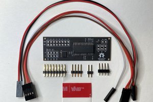
 Steven Stallion
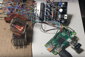
 Maksim Surguy
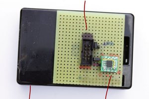
 Yann Guidon / YGDES
I have uploaded the gerber files to OSH Park and shared the project. You can order boards at https://oshpark.com/shared_projects/9he64xQX.