-
1Step 1
Building the Core System
-
2Step 2
Prepare the right angle DuPont connector to be able to accept the ESP8266-01. The way I did it might be considered a bit dirty, but since it's a first prototype it did what I wanted it to do.
- The first thing I did was actually remove pin 5 from the connector. Since the pin wasn't used in this configuration and all the pins surrounding it were common power pins, it made things easier for me to solder if the pin was just gone.
![]()
The right angle connector with the pin removed. I used the protoboard afterwards to make sure any bent pins were put back in place before I started soldering.
![]()
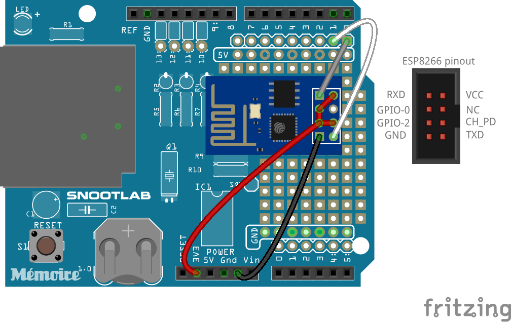
Wiring diagram and pinout of the ESP8266-01, to help follow along
- Next, I wired the 3.3V, GPIO-0, GPIO-2 and CH_PD lines together. The 3.3V line is obviously the power input, and the other pins we want to keep artificially high at all times (GPIO-0 updates firmware when the signal is LOW, GPIO-2 has to be high or the chip won't boot, and CH_PD is a power save function; low it goes into standby, and high it's fully operational). For me, I wrapped a stripped piece of wire around the four pins (so much easier with that other pin removed!), soldered it shut and then wrapped it in electrical tape to make sure none of the other pins came in contact. At this point, I started doing continuity tests at each stage of my work to make sure nothing was shorted together that wasn't supposed to be.
![]()
Definitely would not do this on a production model!
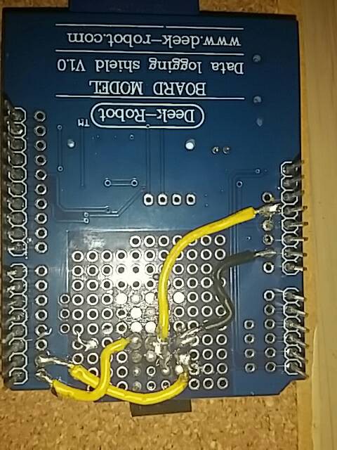
- Solder the connector onto the board. I'd place the ESP chip in the holder just to make sure you have the right clearance. On my board, I used the 3rd and 4th row of the proto-board.
- At this point, it's basically connecting the wires in place. Any of the jumpered pins gets sent to the 3V3 power pin, Ground to Ground, RXD to DIG_0 on the Arduino, and TXT to DIG_1 on the Arduino (D0 and D1 are the Arduino's TX and RX, respectively. Remember, the Arduino TX's to the ESP's RX, and the Arduino RX's info from the ESP's TX!)
I know, wire color coordination complete fail! I didn't find the other color I was looking for for the data lines until after I'd finished wiring all of them. The top yellow wire is the 3V3 line, so even though it looks dirty it's not that important because I have my choice of four pins to connect to. Black is ground and the other two are the TX and RX pins.
- One last test to make sure nothing got cross wired (bad solder connections, especially at the 3V3 connection will make the chip go 'poof' very quickly!) and then covered the connections with a layer of electrical tape, and we're done!
A little electrical tape goes a long way to keep stuff from blowing up!
Hacktip: If you don't have a multimeter handy (like I did, whoopsie!) here's a quick and dirty continuity tester I made out of some of the other components I was using
-
3Step 3
Learn your sensor's baseline
Since it seems that different types of moisture sensors have different outputs, not to mention different soil types and plants require different amounts of water, it's a good time to figure out what a nominal value would be for your particular sensor. A quick hook up of a sensor and a tiny sketch for the Arduino will give you a real time measurement so you can play with the dirt and get the right values.
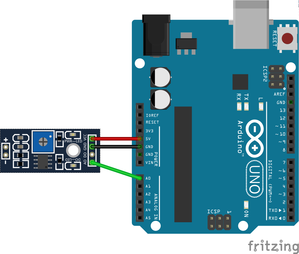
![]() Here's all you really need for this part. I'm doing it on the shield, just because I want to get used to having the other parts to worry about.
Here's all you really need for this part. I'm doing it on the shield, just because I want to get used to having the other parts to worry about./* # Baseline code for moisture sensor # Editor : Heather-Lynne Van Wilde # Date : 24.12.2015 # Version : 1.0 # Original Source : http://www.dfrobot.com/wiki/index.php?title=Moisture_Sensor_(SKU:SEN0114) # Connect the sensor to the A0(Analog 0) pin on the Arduino board */ void setup(){ Serial.begin(9600); } void loop(){ Serial.print("Moisture Sensor Value:"); Serial.println(analogRead(A0)); delay(1000); }Full disclosure: The code is indeed copied from DFRobot's wiki, but with a few changes- Their moisture levels didn't correlate with my sensor (on theirs, the wetter the soil, the higher the value, on mine it was the opposite. Bone dry dirt was about 1100, almost good soil about 90)
- The baud rate was -way- too fast for my Arduino to read. I have a clone with a non-FTDI chip, and the 56K they called for was both unneccesary and caused errors in avrdude. I did confirm with my parther's genuine UNO that the faster speed does work though.
- I massively slowed the delay. I didn't need a dozen reads a second. It's dirt, not a radio signal after all.
-
4Step 4
To be continued ...
Arduino Grow Chamber
Automating feeding and watering of secluded plants via WiFi in a pseudo-IoT system
 Heather-Lynne Van Wilde


 Here's all you really need for this part. I'm doing it on the shield, just because I want to get used to having the other parts to worry about.
Discussions
Become a Hackaday.io Member
Create an account to leave a comment. Already have an account? Log In.