Luke J. Barker
roboShield makes programming robots much easier (spelled FUN!) and gives your robot a voice of his (or her) own!
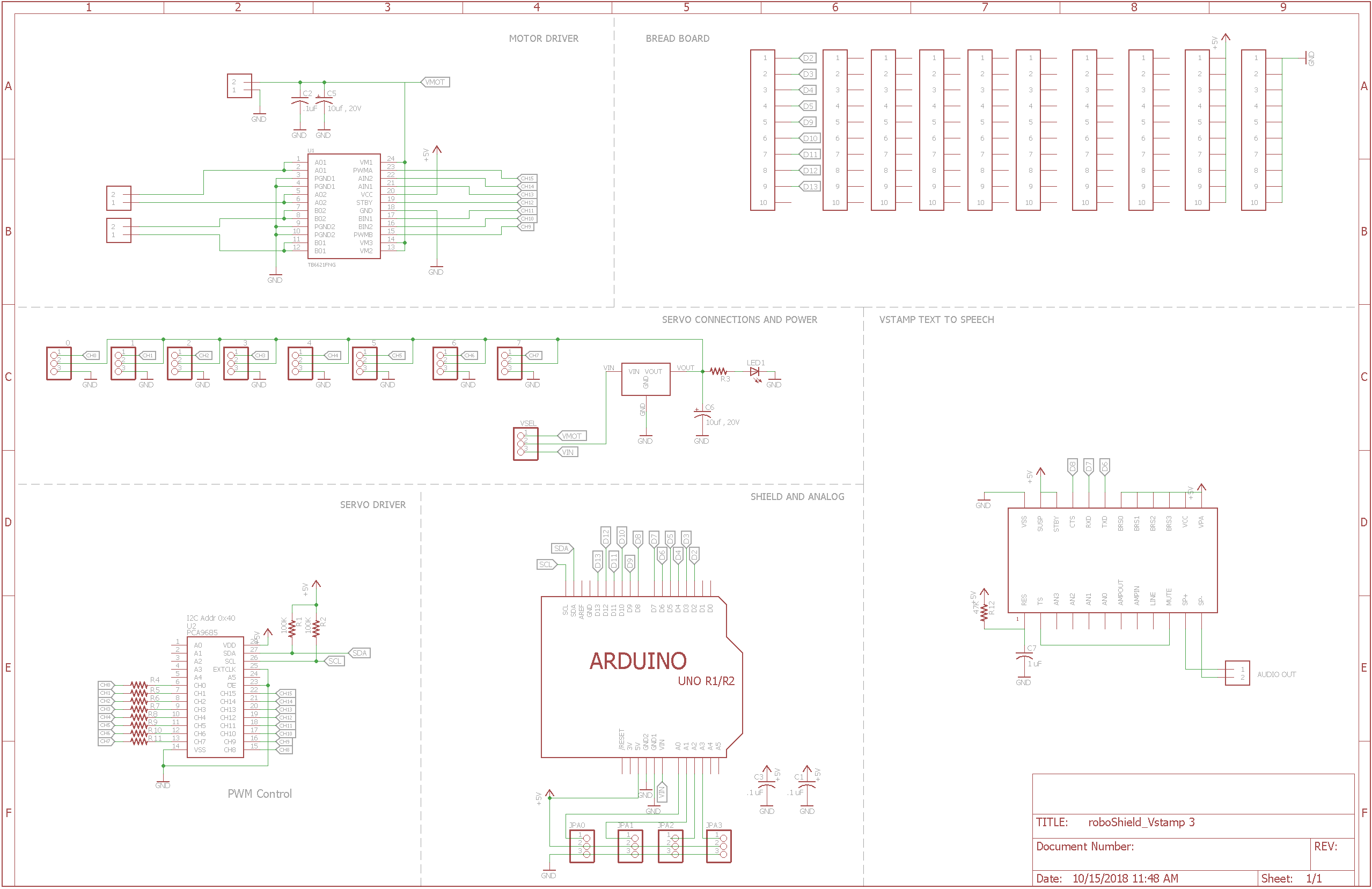
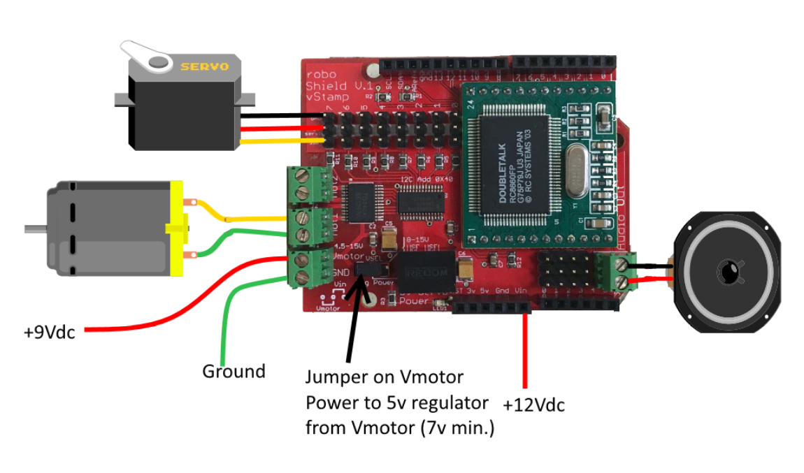
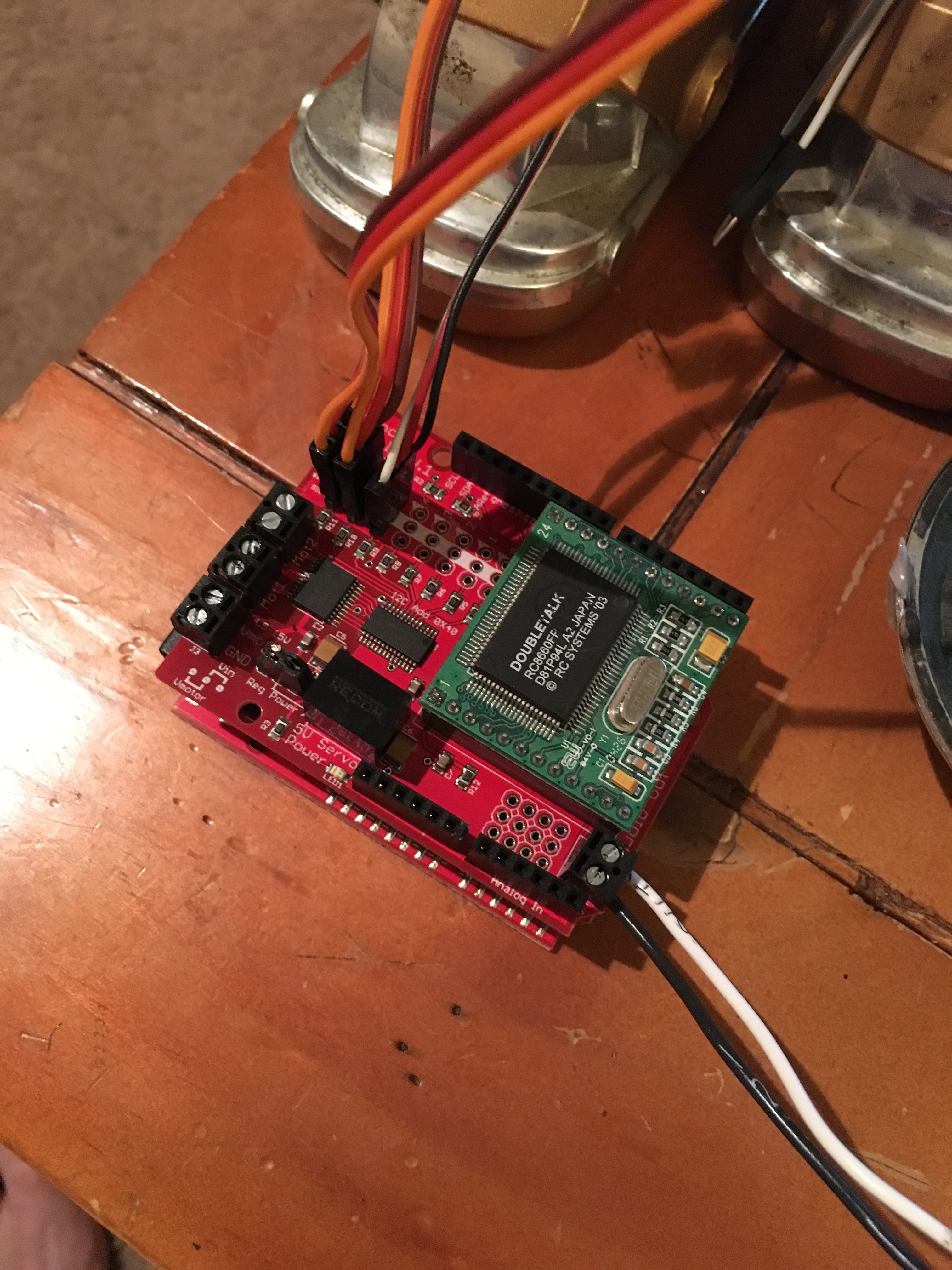
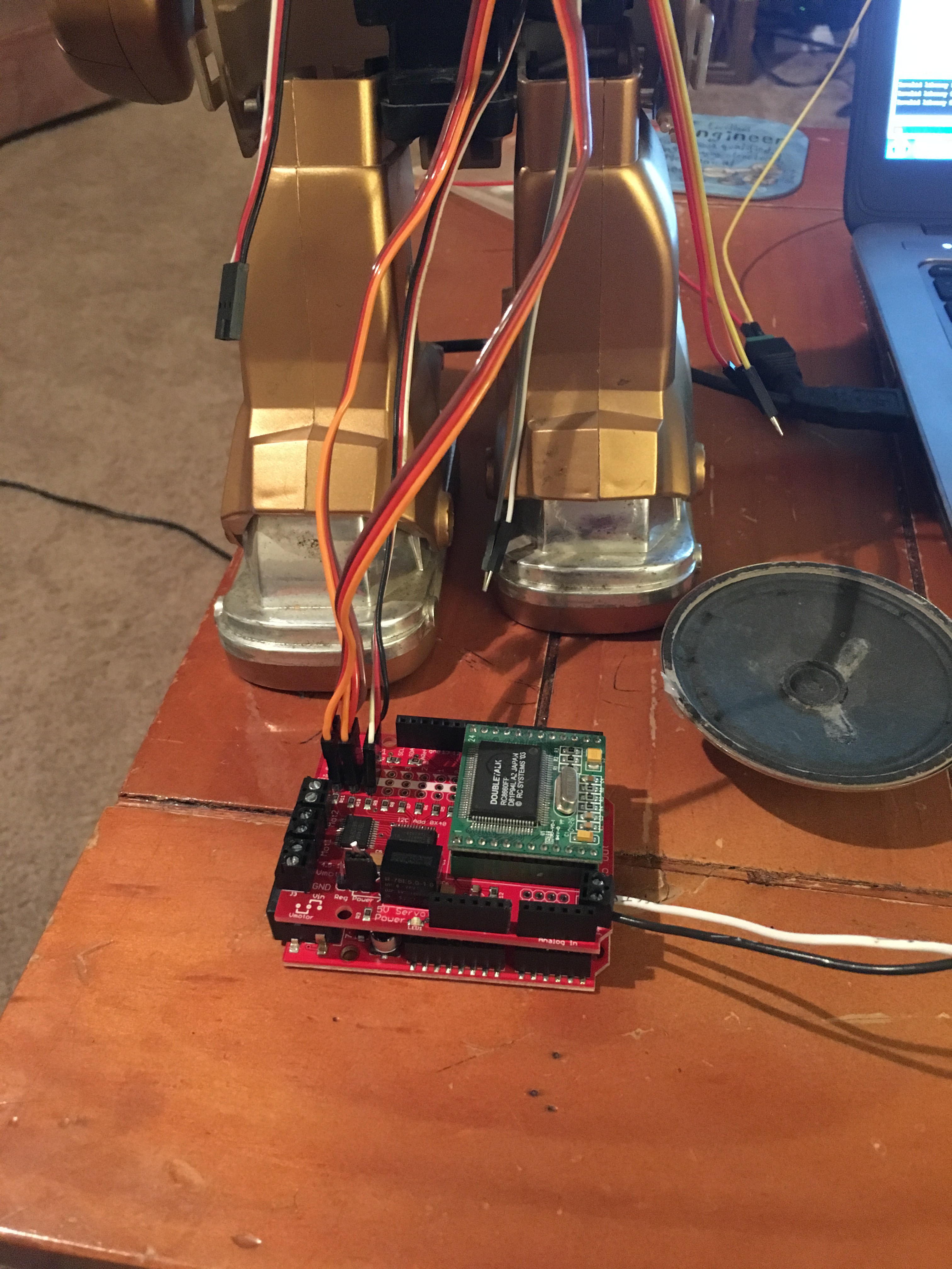
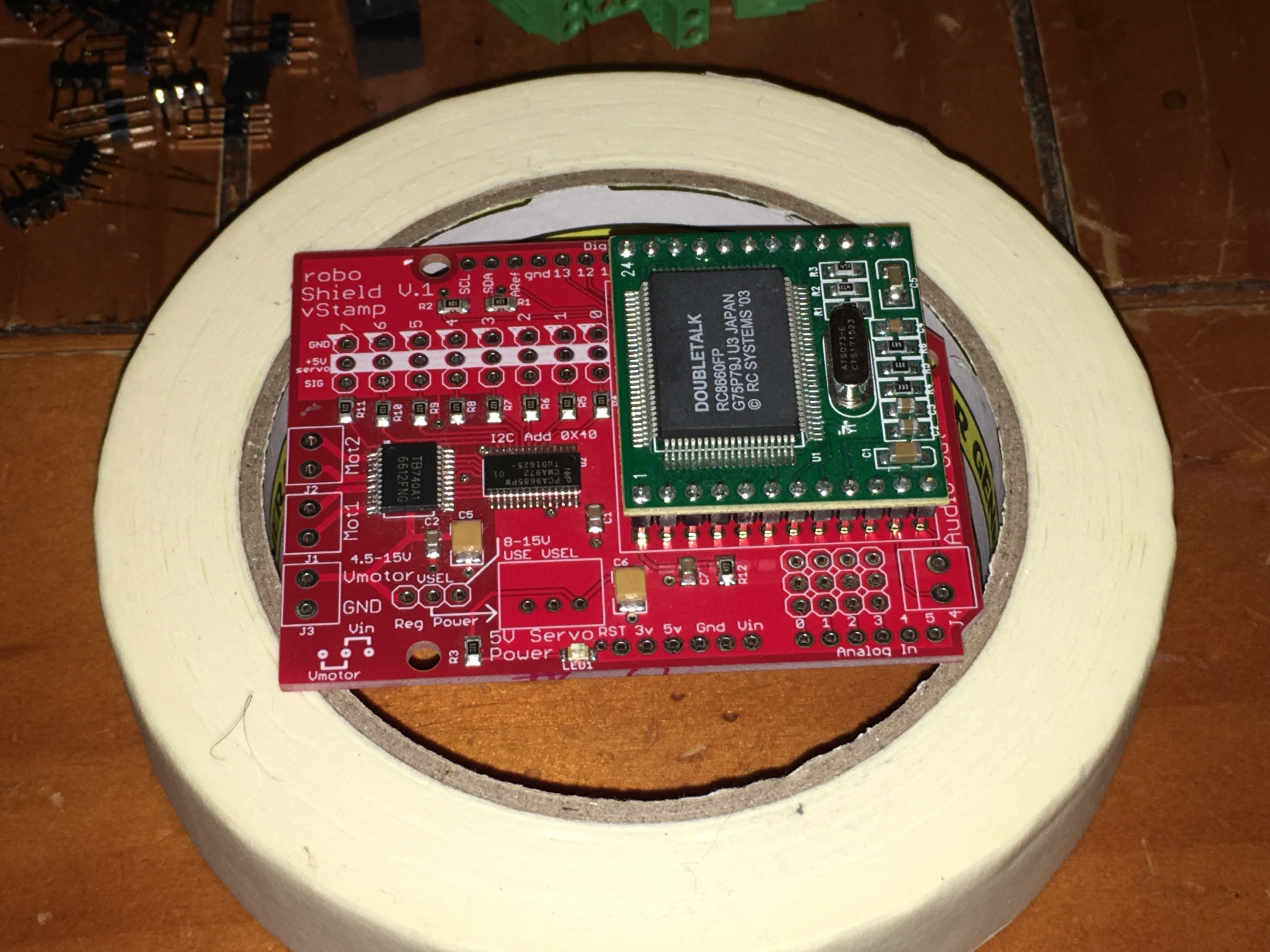
The roboShield was designed to help solve IO and timing problems when building robots with an Arduino. Programming an Arduino to run (PWM) servos and motors and at the same time send Software-serial data can cause glitches in the firmware and hardware. There are ways around this with the use of many different libraries but there also had to be an easier way.
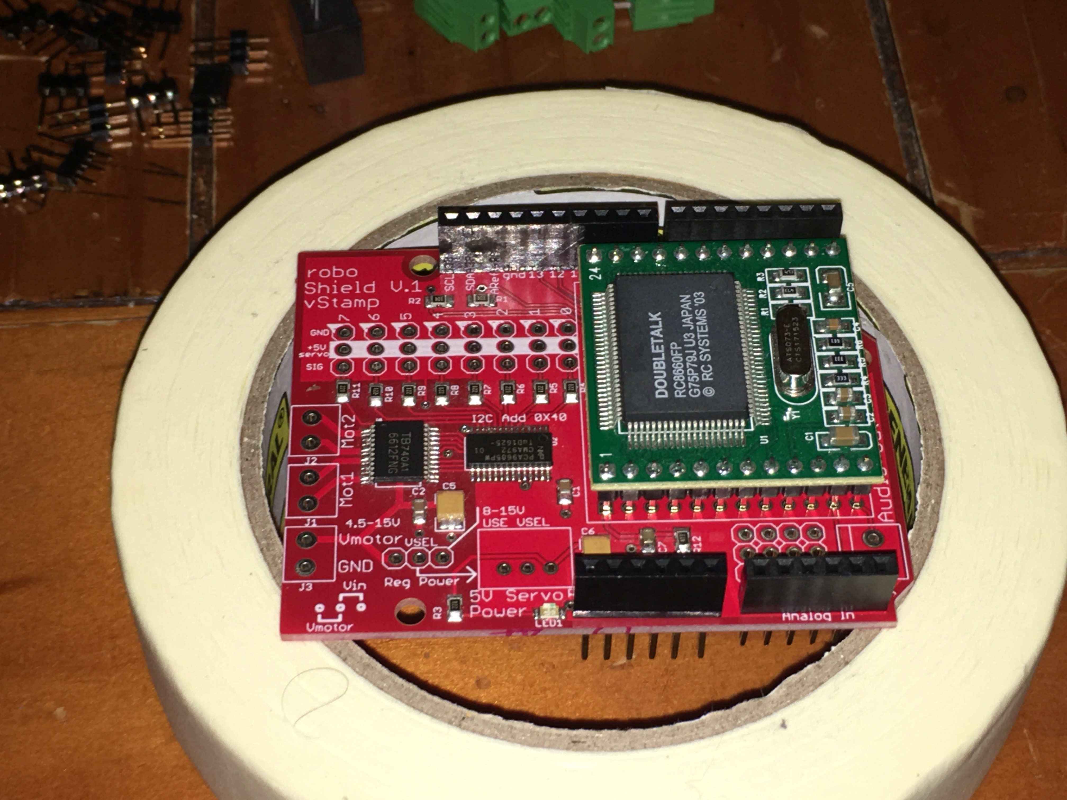
The best method was to put an independent PWM controller on a shield to control the servos. After looking at all the IO of the PCA9685, I realized some of those pins could easily control the TB6621 motor controller as well.
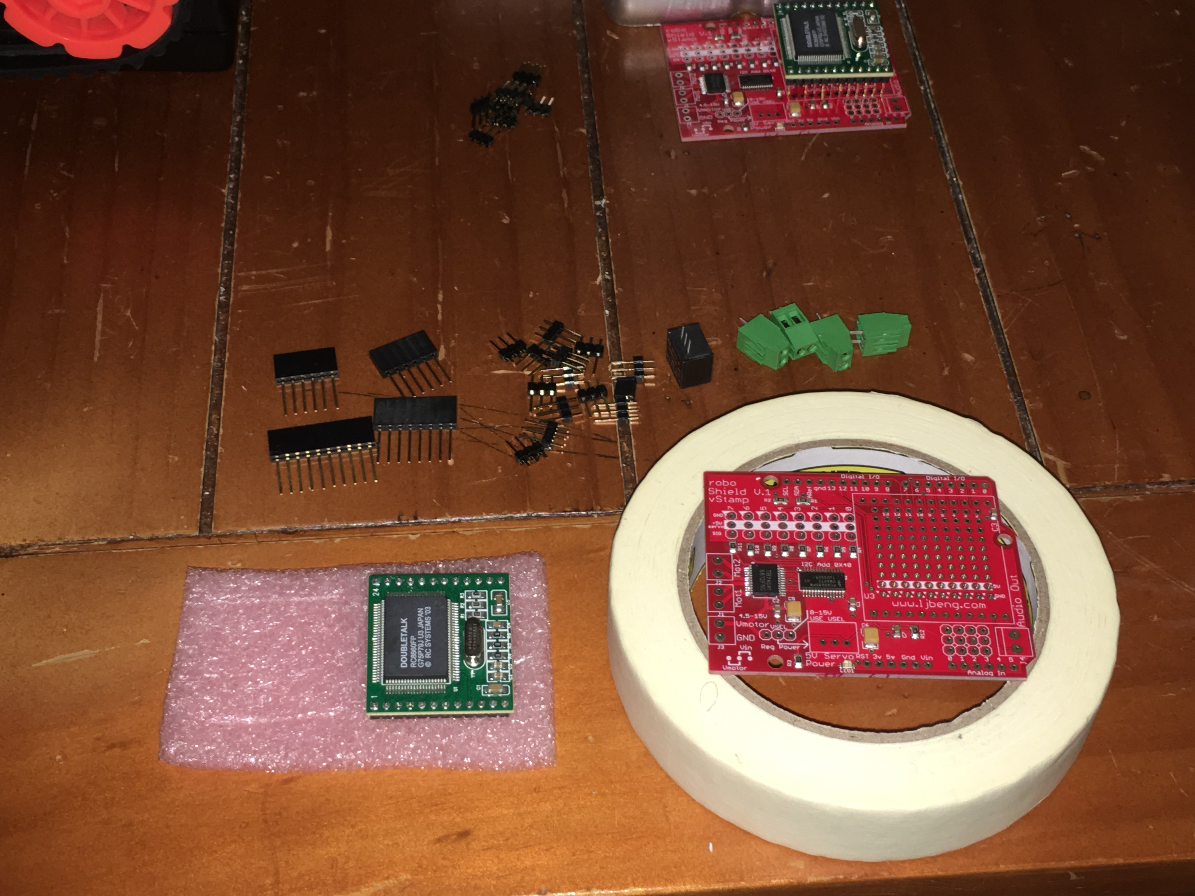
By moving all the motion functionality from the Arduino to the sheild, roboShield freed up my program to do some real timing while giving motion commands seamlessly. Adding the V-Stamp text to speech converter was an easy task and gave great results for adding voice output to the shield. V-Stamp is a module produced and sold by RC Systems (www.rcsys.com)
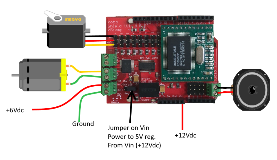
This shield gives the programmer control of 8 servos, 2 dc motors (including direction and braking) and a Text to Speech converter all while using only 3 IO pins. This leaves a lot of room to make your robot program grow.
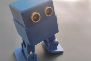
Bring your defective robot to life with one simple-to-use roboShield!
Features:
- PCA9685 connects to Arduino. I2C communication operates Servos and the Motors.
- TB6621 for PWM speed control of 2 motors. (Digital connections to PCA9685 frees up Arduino Pins)
- Simple external connections to Servos, Motors, Sensors and a Speaker for voice.
- Only 2 Arduino pins for Servo and Motor Control
- Only 1 Arduino pin for Serial Text to Speech using the V-Stamp module.
- The Arduino library is complete and available on Github.
- Independent 5V source for Servos (so the 5v regulator on the Arduino doesn't get overloaded)
Specs:
- Motor Power supply voltage: VM = 15V max
- Output current: Iout=1.2A(average) / 3.2A (peak)
- Motor driver built-in thermal shutdown circuit and low voltage detecting circuit
- Default I2C address is 0x40.
- Speech incorporates a 1 Watt amplifier into an 8 Ohm speaker.
- Serial Volume control built into the library.
- Select from 11 different voice intonations.
- 5V on board switching regulator provides up to 1 Amp for Servos and other peripherals.
Benefits:
- Independent servo control frees up the Arduino code.
- Independent motor control again, frees up the Arduino.
- Simple Text to Speech serial control with 1 Watt of output power gives your robot a clear voice.
- Get your robot running much faster with fewer libraries.
- Voice is an optional add on module
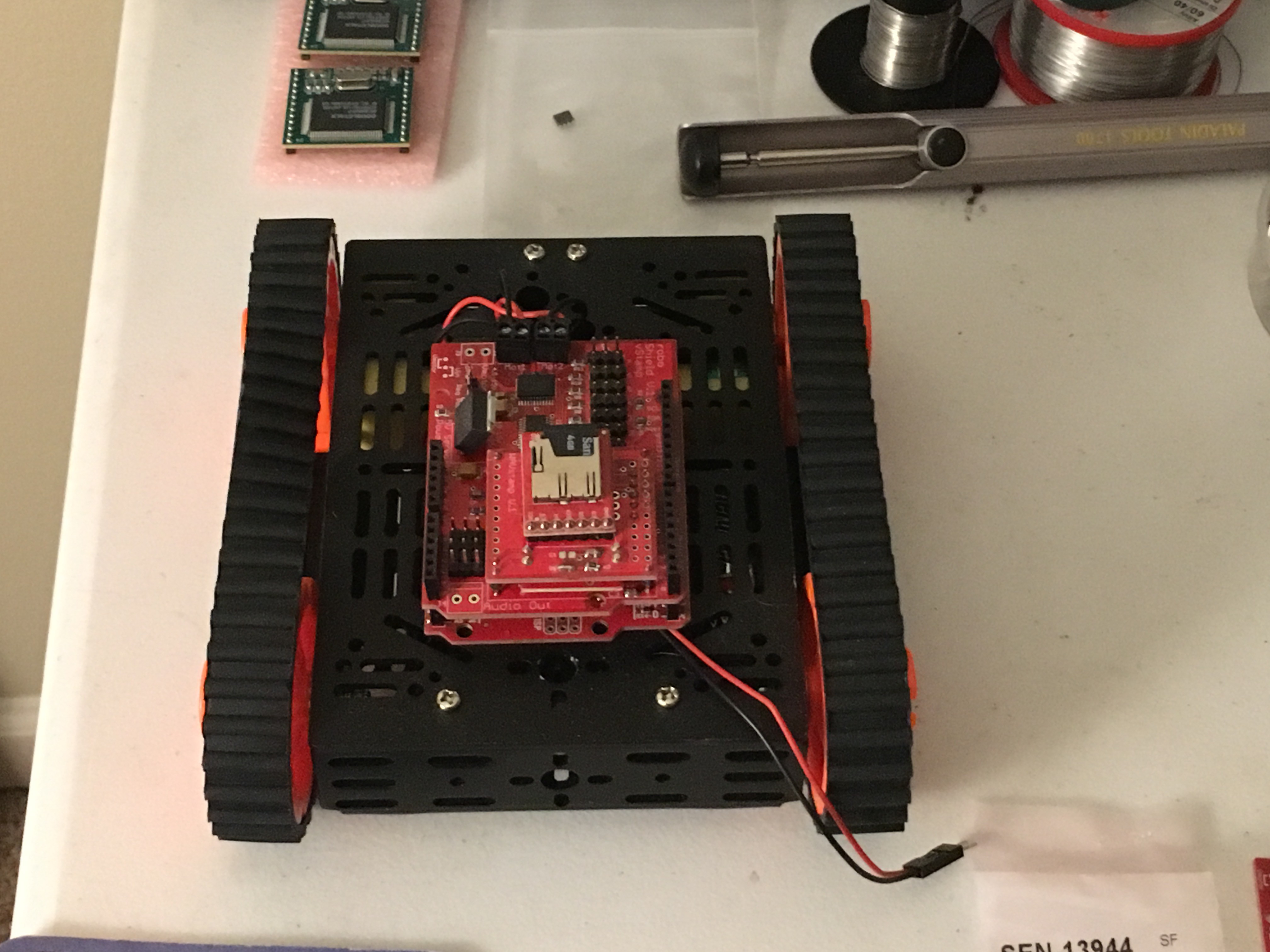
- Bread board space under the V-Stamp module
V-Stamp Voice Choices:
1. PerfectPaul
2. Vader
3. BigBob
4. PrecisePete
5. RicochetRandy
6. Biff
7. Skip
8. RoboRobert (Used for most Toby and Mike demos)
9. Goliath
10. Alvin
11. Gretchen
Spoiler... No "speech recognition" was used making this video....
That Video was made before the current roboShield was back from production with the older protototype. You will notice a jerk on all servos when the text to speech converter was activated. roboShield fixed that problem.
The next video, Toby got some updgrades and is using the current roboShield...
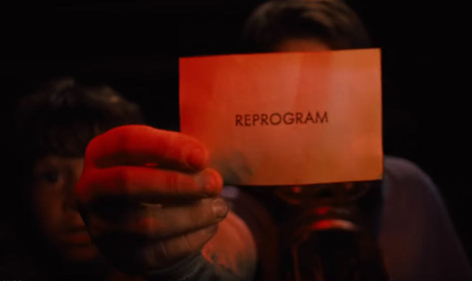
Even in Zathura, the defective robot was fixed with one simple card...

 Ahmed Azouz
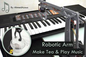
 Vittorio Loschiavo