Close
0%
0%

PCB stepper motor

... is designed for direct drive wheels for swarm robots

Similar projects worth following
PCB stepper motor is designed for direct drive wheel for swarm robots

Coils are etched on 4 layer PCB, about 40turns for one coil (8coils).

PCB stepper motor is  certified as open source hardware by the Open Source Hardware Association.

Thanks to OSH for park support !!!

Check my 2D X-Y linear micro actuator
https://hackaday.io/project/154496-2d-actuator-move-micro-robot-in-xy-2d-space

I am inspired with great project https://hackaday.io/project/39494-pcb-motor

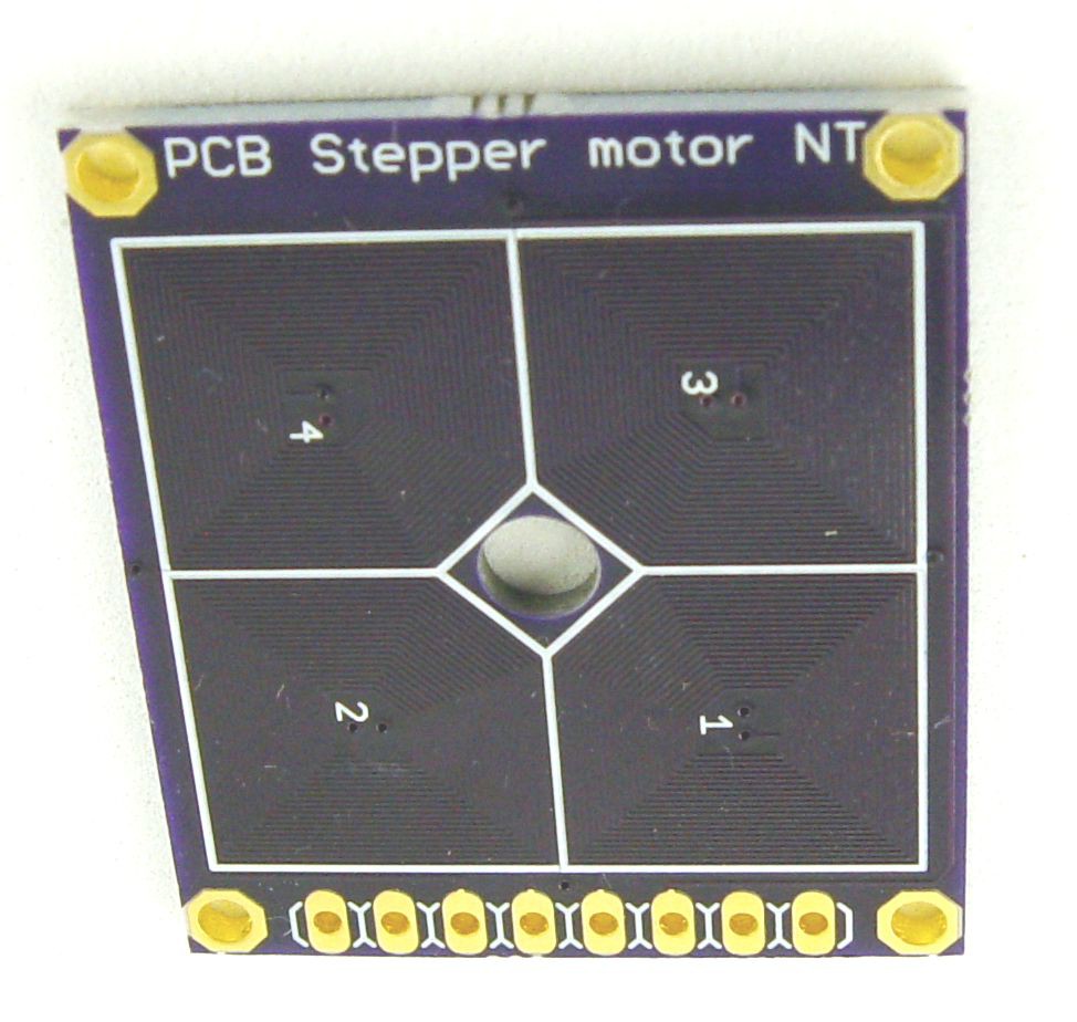
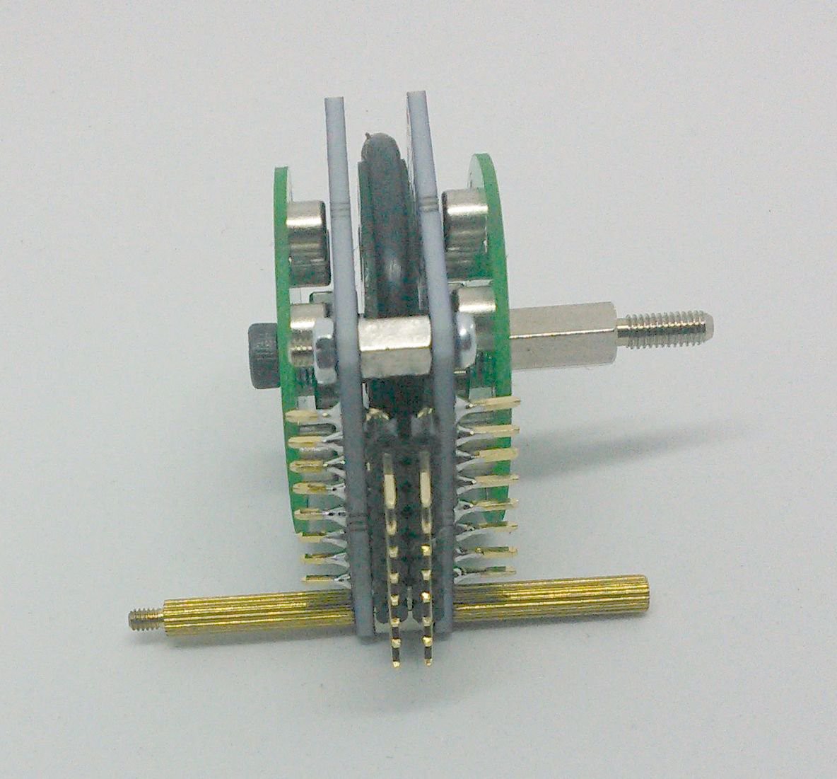
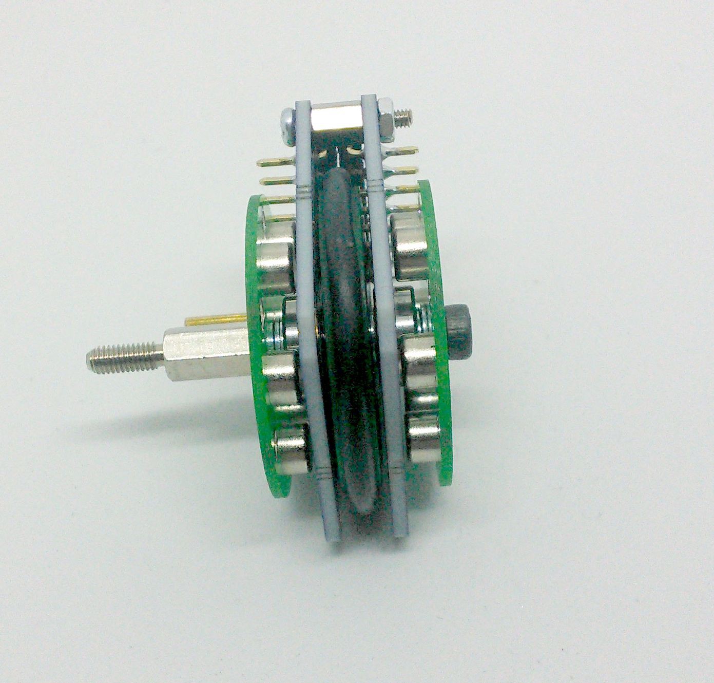
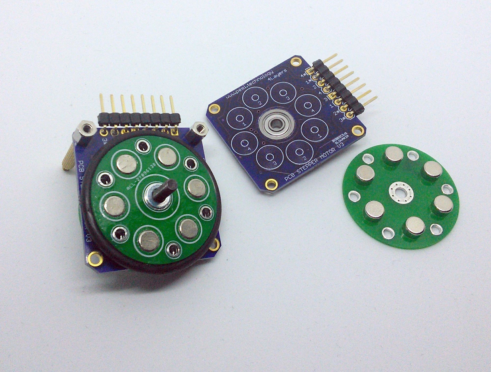
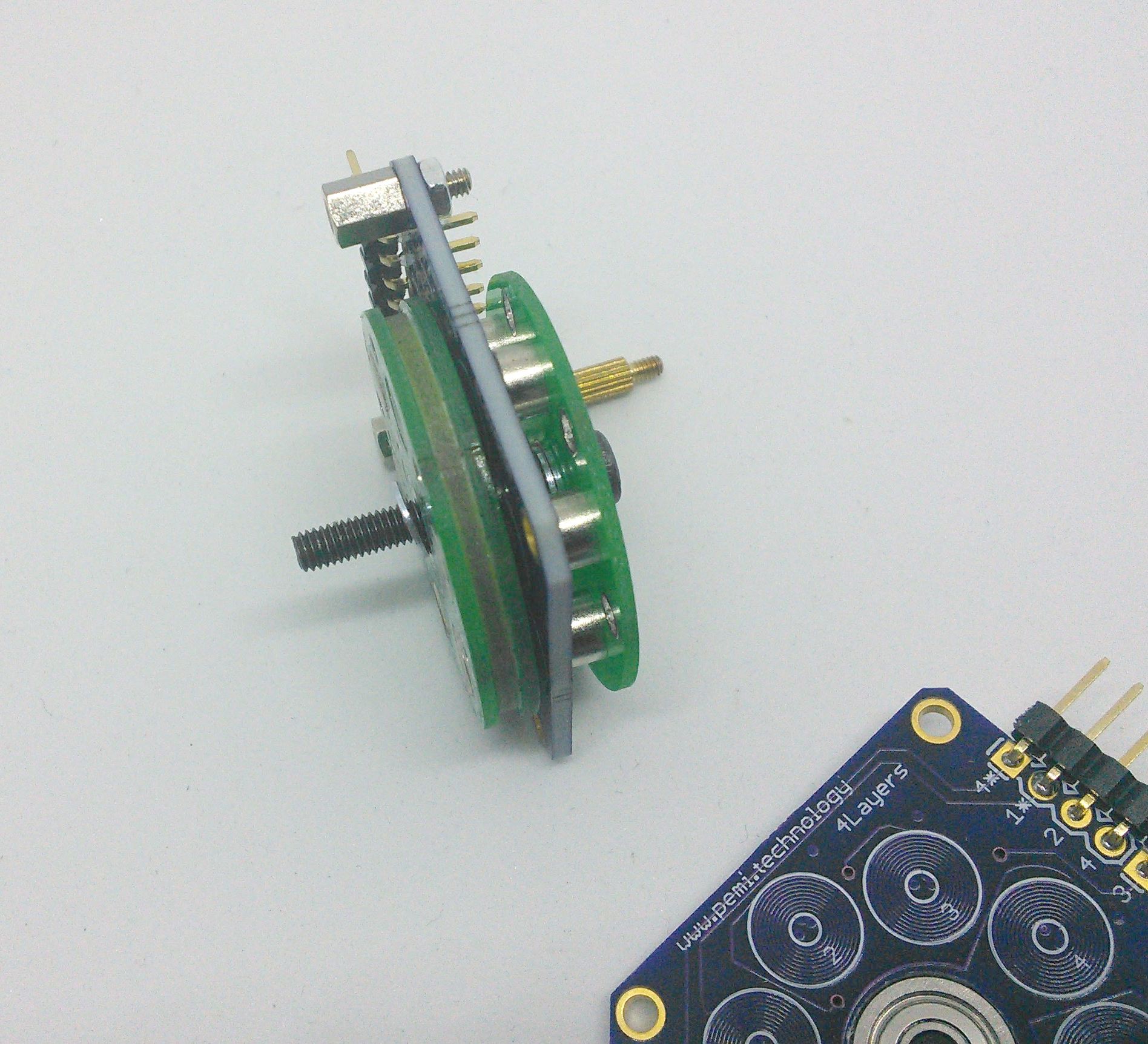
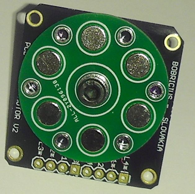
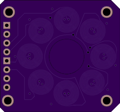
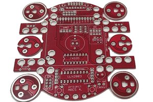
Instead of printed rotor I am using PCB rotor (3 layers of 1mm PCB and 5x3mm magnets)
middle layer rotor PCB have 1mm smaller diameter and making rim for simple rubber
ring tyre

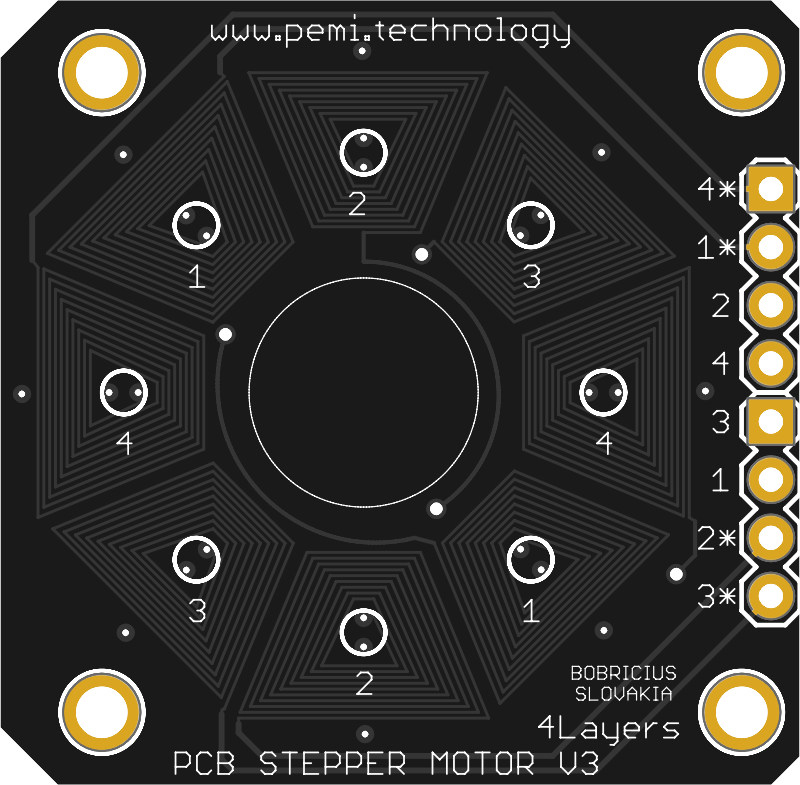
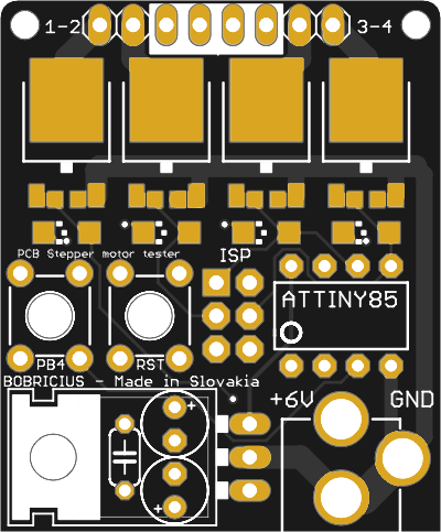
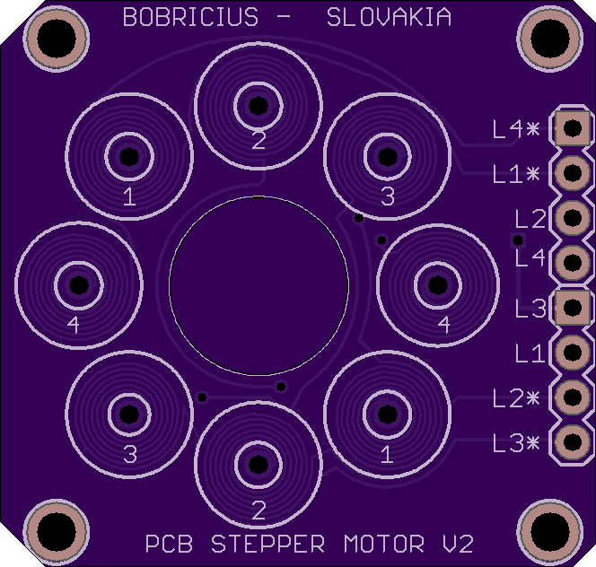
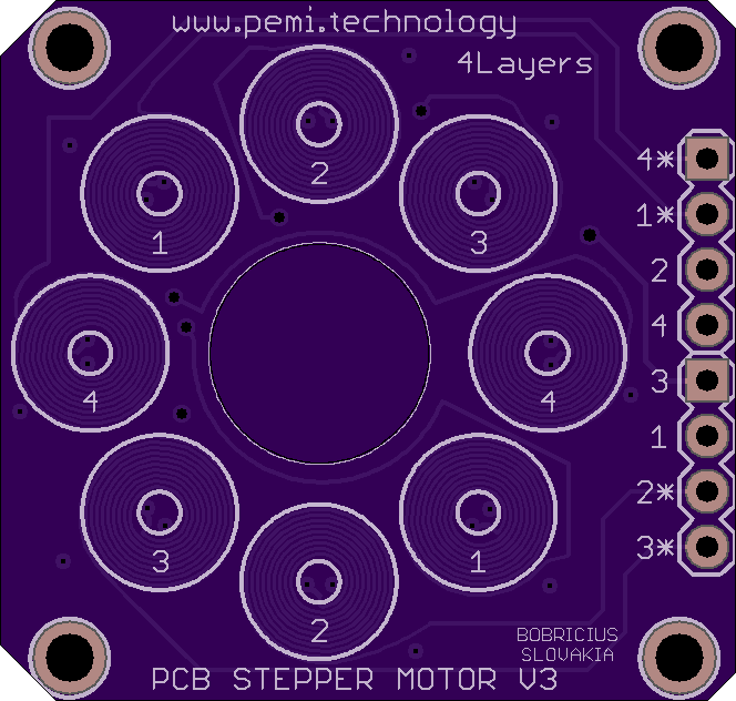
Board can be easy configured to unipolar or bipolar mode

  •  4 layer 40 turns per coil !

HACKADAY article https://hackaday.com/2018/03/28/a-brushless-motor-on-a-pcb-made-from-pcb/


x-zip-compressed - 108.16 kB - 04/17/2018 at 06:36

Download

x-zip-compressed - 109.93 kB - 04/17/2018 at 06:35

Download

brd - 267.53 kB - 04/17/2018 at 06:34

Download

sch - 49.11 kB - 04/17/2018 at 06:34

Download

brd - 766.12 kB - 04/17/2018 at 06:34

Download

View all 6 files

  • 6 × MAGNET 5x3MM
  • 2 × bearing SKF623-2Z
  • 2 × Outer PCB wheel
  • 1 × Inner PCB wheel
  • 2 × Coil PCB make magic

View all 7 components

  • SK000001

    bobricius12/07/2018 at 14:13 0 comments

    PCB stepper motor has now officially been certified as open source hardware by the
    Open Source Hardware Association.

  • New coil board

    bobricius10/16/2018 at 12:44 0 comments

    It is time for new coil board

    • better coil shape
    • better coil connection

    Hamburger structure with 3 wheels is very reliable, precise aligned and use all magnetic field from both sides. also speed and temperature at 2,5V is usable for long time operation

  • Some speed

    bobricius09/14/2018 at 19:11 0 comments

    I have try add some speed .... at 2,5V boards have acceptable temperature

  • New board test

    bobricius09/07/2018 at 20:19 0 comments

    I received new coils ... I can just say older are better, but this new are good as simple stepper demonstrator,

    12 steps per rotation, board is simple, working almost without heat :)

  • new version on way

    bobricius07/28/2018 at 20:41 0 comments

    to reduce cost I am try maximize space on 4-layer board

    Also I separating to 4layer coil board + bearing board with driving demonstrator

    4 coils with about 80 turns (hand painted), only 3 magnets 10mm or 5mm

    Also some coil variants, ordered in OSH park great 4 layer service.

  • More pictures ....

    bobricius05/06/2018 at 20:08 0 comments

    Finaly I get second bearing ...now is motor assembled to final hamburger structure.

    I add 2 wheels with magnets to outer side, significantly improve torque.

    Check run video !!!

    - header detail

    -assembled motor

    -Inside motor

    -Unipoar tester

    -Rim detail ... inner wheel is smaller

  • 0.8mm boards from OSH park arrived !

    bobricius04/18/2018 at 11:55 0 comments

  • Unipolar stepper motor tester

    bobricius04/03/2018 at 08:23 0 comments

    stepper motor support bipolar and unipolar mode, but there is no high current driver for unipolar mode

  • 2 layers design ready for OSH Park

    bobricius04/02/2018 at 14:28 0 comments

    This is experimental redesign first board

    but on 0.8mm 2oz board

    2 layer board of 1.30 x 1.18 inches (33.0 x 29.9mm) 
    3 boards will cost $7.65

  • 4 layers PCB ready for order form OSH Park

    bobricius04/02/2018 at 14:18 1 comment

    Finishing design,

    In my life it is first 4 layers design

    spec.

    10 turns per layer 2 coils in series

    4 layer board of 1.35 x 1.26 inches (34.3 x 32.1mm) 
    3 boards will cost $17.00

View all 11 project logs

View all 5 instructions

Enjoy this project?

Share

Discussions

luis hs wrote 11/12/2019 at 17:17 point

Hello.

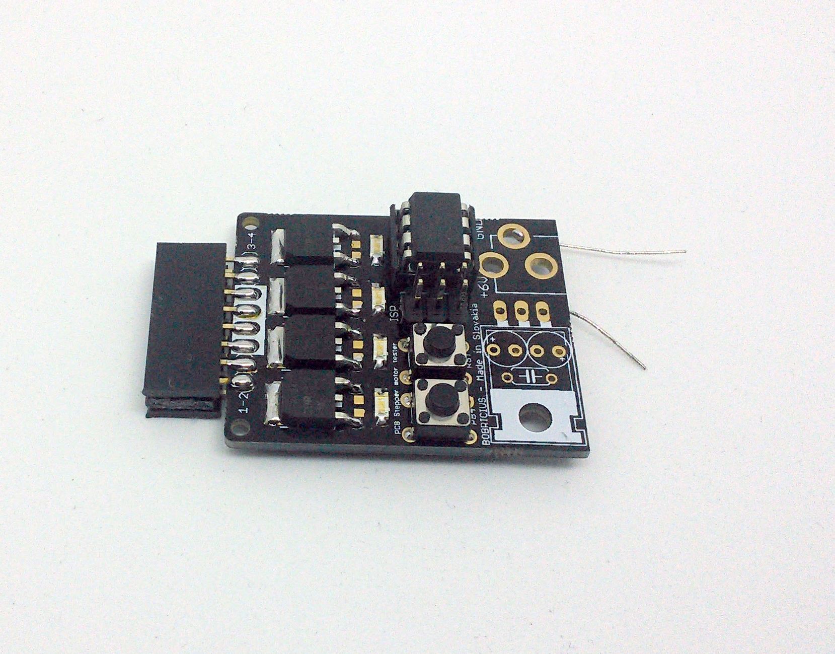
Is it available to download the scheme and the PCB you use to control your stepper motor?

Regards

  Are you sure? yes | no

bryklinop wrote 09/08/2019 at 12:25 point

Excellent !! really nice posts! thanks

<a href="https://192168101.mobi/192-168-100-1.php">192.168.100.1</a>

https://192168101.mobi/192-168-100-1.php

  Are you sure? yes | no

Patrick Ryan wrote 04/19/2019 at 02:08 point

Why 4 layers?

  Are you sure? yes | no

Vincent wrote 09/15/2018 at 10:05 point

Hi Peter,

Wndering about smaller coil/magnet size as my project would require only about 20rpm... Engine is too efficient with this setup :)

  Are you sure? yes | no

28raining wrote 08/03/2018 at 06:40 point

Awesome project Bob!

I ordered one of your PCB's and am using it with an adafruit stepper motor hat on top of my PI. It's spinning :) Now just trying to decide on how to build my custom driver board.

Are you driving the coils with 5V? Did you experiment with higher voltages? Do you know how much on-resistance your MOS switches have (or the resistance of the coil?)

Also, did you experiment with 6mm diameter magnets?

Keep up the good work

  Are you sure? yes | no

bobricius wrote 08/03/2018 at 07:22 point

Hi, It is amazing to read that this project is replicable. 

I want try new 4 coil board with 10mm magnets, They are in factory now.

Higher voltage produce more heat. Lasth month I was focused on other projects, now I am going back to motor. Resistance of coil you can measure with multimeter. I selected random logic input Mosfet with switching current about 30A but I thing 2A is enough :) I used only 5mm magnets, I have no other dimensions,  just yesterday I received 10mm.

  Are you sure? yes | no

xihongyuan wrote 07/16/2018 at 01:36 point

如何提高汽车PCB的缺陷率 http://www.pcbindex.com

  Are you sure? yes | no

Hari Wiguna wrote 06/14/2018 at 13:59 point

Wow... Just heard about your motor.  Ingenious! Love it!

  Are you sure? yes | no

Yann Guidon / YGDES wrote 06/13/2018 at 06:57 point

Congrats Bob !!!

  Are you sure? yes | no

bobricius wrote 06/13/2018 at 12:56 point

Thanks Yann !

  Are you sure? yes | no

rbruno96 wrote 06/13/2018 at 01:14 point

Congratulations! This is a very creative project; despite of stepper mottors being pretty cheap, sometimes it's better and easier to implement them in PCB. Integrated driver, that's very cool; have you seen dual NMOS SOIC-8 ICs? Maybe using two of them you'l get a smaller PCB and a lower cost, I don't think you need such a high power D-PAK transistors... you could search for a SOIC-THERMAL-PAD package if you think it will heat so much.
In general these SOIC transistors are very good, low Cgs and RDS (i'm talking about tenths of ohms), you should consider them. SMD Attiny are available also. Consider using a 10 ohm resistor in series with MOS gates; this will avoid oscillations when turning the transistors on and off because of the overshoot.
Could you provide us some mechanical measurements? Such as power, torque, acceleration and so? I think here we have a very good oportunity to implement accurate stepper motors in cheap projects (and toys and so).

Congratulations again! keep going!.

  Are you sure? yes | no

bobricius wrote 06/13/2018 at 07:06 point

Thanks. Stepper tester was half day quick project to test motor. In unipolar mode work much better than in bipolar. I know about smd components I next version I try combine driver and coils on one board. now is separated because driver do not need 4 layer board also I need stack 2 boards for better bearing hold, Also I add 2 more wheels to use wasted magnetic filed from opposite side of board.

  Are you sure? yes | no

abuse.twink wrote 04/03/2018 at 12:32 point

I take off my hat, it's a very good job, thanks for telling me https://192168ll.mobi/ 192.168.l.l

  Are you sure? yes | no

Carl Bugeja wrote 03/29/2018 at 16:28 point

Great job :)

  Are you sure? yes | no

WestfW wrote 03/29/2018 at 07:55 point

Very nice.  Did the usual board shops accept it as a single 100x100mm PCB, or did they charge you for "multiple designs" ?

  Are you sure? yes | no

bobricius wrote 04/01/2018 at 10:06 point

dirtypcb accept this

  Are you sure? yes | no

danjovic wrote 03/28/2018 at 22:13 point

Amazing! Can you run it on steps? so you can have a mechanical display! What about adding a second board on the opposite side of the rotor with coils in one board placed in between the coils on the other board, like a hamburger with coils for buns and magnets as the meat.

  Are you sure? yes | no

bobricius wrote 04/01/2018 at 10:09 point

untested now, I need redesign coils to connect opposite coils, now they are hard wired under board. I had hamburger plan but Chinese bearings are very bad, so for test i connect one board only.

  Are you sure? yes | no

Duke Circuit Co.,Ltd wrote 03/17/2018 at 04:02 point

what it would be exactly use for?

  Are you sure? yes | no

bobricius wrote 04/01/2018 at 10:09 point

it is for testing pcb manufacturers :)

  Are you sure? yes | no

Makerfabs wrote 03/13/2018 at 08:21 point

Great project!~ 

  Are you sure? yes | no

Similar Projects

Does this project spark your interest?

Become a member to follow this project and never miss any updates