Close
0%
0%

Confagrid

Software and Hardware to make Word Clocks easier to make

Similar projects worth following
I've always liked Word Clocks and wanted to make one, I found it hard to be creative and different because fitting all the phrases that I wanted for different times was difficult and cumbersome so I started writing software to make it easier. I want to provide a combination of software tools and open hardware to make creating unique Word Clocks easier.

Brian @Benchoff wrote a great summary of this project on hackaday.com back in April when it was submitted for the Hackaday prize: https://hackaday.com/2018/04/17/automating-the-design-of-word-clocks/.

The application for laying out the Word Clock grid is licensed with the MIT license which is a short and simple permissive license with conditions only requiring preservation of copyright and license notices. Licensed works, modifications and larger works may be distributed under different terms and without source code.

All Hardware designed and created for this project is licensed with Creative Commons Attribution Share Alike 4.0 (CC-BY-SA-4.0) which is similar to CC-BY-4.0 but requires derivatives be distributed under the same or a similar compatible license.

confagrid_capture.PNG

Edit View screen capture

Portable Network Graphics (PNG) - 723.08 kB - 03/13/2018 at 01:37

Preview
Download

  • 1 × IS31FL3733 The IS31FL3733 is a general purpose 12×16 LEDs matrix driver
  • 1 × ESP32 SoC microcontroller with integrated Wi-Fi and dual-mode Bluetooth

  • Blinky Stage 2

    Stephen Legge06/12/2018 at 05:39 0 comments

    I decided that I would try the ESP32 as the main microcontroller for Confagrid, I was going to need some sort of wireless communication and the microcontroller in the ESP32 looked plenty capable and the ESP-IDF based on FreeRTOS looked like it would be decent to work with.  I liked that it used GCC and had lots of example code.

    The only issue I had with the examples is that they were all using C and I wanted to use C++ but it wasn't too much trouble to re-work them to be more C++ friendly, it's currently a bit hacky but will be much easier to clean up and maintain.  It doesn't look pretty, but I was able to get a Blinky running on the ESP32 communicating over I2C to the dev board that I made.  It may not seem too impressive, but since the main part of the project is turning LEDs on and off, it is a big step.  Once I figure out what I'm going to do about powering the clock I should be able to create an all-in-one board for the prototype and then I can focus on getting the firmware and backend stuff working together.

  • I2C to IS31FL3733 with the Bus Pirate

    Stephen Legge06/02/2018 at 02:53 0 comments

    I'm really glad I picked up a Bus Pirate, it makes figuring out the I2C communication with the IS31FL3733 pretty slick.  Instead of trying to compile/re-compile/flash a binary for some micro, you can just try to interact directly with the peripheral and get immediate feedback and figure out what works.

    Here's how I turn on LED[0,0] (CS1 to SW1).

    The Bus Pirate starts out with a 'HiZ>' prompt, you hit 'm' to change modes and then select the mode you want (I wanted I2C for the IS31FL3733, which is 4).

    HiZ>m
    1. HiZ
    2. 1-WIRE
    3. UART
    4. I2C
    5. SPI
    6. 2WIRE
    7. 3WIRE
    8. LCD
    9. DIO
    x. exit(without change)
    
    (1)>4
    Set speed:
     1. ~5KHz
     2. ~50KHz
     3. ~100KHz
     4. ~400KHz
    
    (1)>4
    Ready


    Then you need to turn the power supplies on with 'W'.

    I2C>W
    Power supplies ON

    Now you can communicate over I2C with formatted text.  The way I have my dev board configured the address of the I2C slave is '0x50' which you shift left one bit and OR with the R/W bit, so to write I start with '[' for start and then '0xA0' for the device and then register and value.  I don't really understand why, but for the IS31FL3733 you need to change 'pages' in order to write to the registers you want and you need to unlock the ability to change pages each time you need to.  Writing '0xC5' to register '0xFE' unlocks for a one time page change and then you set the page you want at register '0xFD'.

    This is how you unlock the page change register:

    I2C>[0xA0 0xFE 0xC5]


     and then it responds with:

    I2C START BIT
    WRITE: 0xA0 ACK
    WRITE: 0xFE ACK
    WRITE: 0xC5 ACK
    I2C STOP BIT


    I'll leave out the responses for the rest of the commands since they're all just ACKS like that.  So,
    you need to change to page 3 and enable the chip and set the global brightness (I set to full here)

    change to page 3:

    I2C>[0xA0 0xFE 0xC5]
    I2C>[0xA0 0xFD 0x03]


    enable chip and OSD:

    I2C>[0xA0 0x00 0x05]

    set global brightness to 0xFF (255/255):

    I2C>[0xA0 0x01 0xFF]

    change to page 1 (PWM):

    I2C>[0xA0 0xFE 0xC5]
    I2C>[0xA0 0xFD 0x01]

    set first LED to full PWM (255/255):

    I2C>[0xA0 0x00 0xFF]

    change to page 0 (EN/DIS):

    I2C>[0xA0 0xFE 0xC5]
    I2C>[0xA0 0xFD 0x00]

    set first LED to enabled:

    I2C>[0xA0 0x00 0x01]

    an LED with it's anode connected to CS1 and cathode connected to SW1 will turn on, yay!

    Seems like a lot of work to turn on an LED, but that's just the start.

  • Attempt 2: Partial Failure and then success!

    Stephen Legge05/26/2018 at 05:18 0 comments

    I did a much better job soldering the second board, but I ended up having the same problem as the first one, I could communicate with the chip over I2C, but I wasn't able to actually turn on any of the current sources even though I was getting all the correct responses back from my commands.  I took this as an indication that it probably wasn't a problem with my connections since the chances of only connecting pins allowing me to get power and I2C to the chip but nothing else was probably not likely so I started scrutinizing each connection to see where I might have made a mistake.

    It turns out that it wasn't exactly a mistake, but a combination of following the "Typical Application Circuit" and then not using it in that typical way.

    If SDB is pulled low the chip will essentially shutdown everything other than I2C which was exactly what I was seeing.  This is of course because in a typical setup with a micro controller you would pull SDB high when you wanted it to function, but otherwise it would shutdown to save power, but I was just connecting with the Bus Pirate to try it out and wasn't taking this into account.

    I connected a bodge wire from SDB to the power source from the Bus Pirate and was able to successfully turn an LED on and change PWM settings, etc...  The world makes sense again.

  • Attempt 1: Partial Success, mostly failure

    Stephen Legge05/25/2018 at 00:27 0 comments

    I ordered enough parts for my 3 OSH Park boards and worked on one last week.  I was pretty happy with the results, everything seemed fine and I was able to connect to the chip with I2C with the Bus Pirate but I was unable to get any pins to turn on.  I thought maybe I had a short and tried to re-seat the chip, but I think I may have killed it, I can't connect to I2C anymore.

    I think I will abandon this board and try again with one of the backups.  I guess that's why they come in 3's.

  • IS31FL3733 Matrix Dev Board

    Stephen Legge03/16/2018 at 03:18 0 comments

    I whipped up a dev board to try out the IS31FL3733 chip, I basically took the "Typical Application Circuit" from the datasheet and just brought out all the LED pins to headers and provided a header for the I2C interface with the appropriate pull-ups.

  • Hardware Plans

    Stephen Legge03/13/2018 at 15:51 0 comments

    The software part is coming along nicely, but I also need to start looking into the hardware part.

    I started mocking something up based on other projects I've seen in the past using an Ikea picture frame.  Laying out spacing of the letters and LEDs seems like 16x12 or 12x16 is a good ratio to start with and should work for a standard word clock and more.

    Coincidentally I stumbled across a chip IS31FL3733 that is a general purpose 12×16 LEDs matrix driver which sounds like it could work out perfectly for what I need.  I'm going to get ahold of a few of these and see if it lives up to the hype.

View all 6 project logs

Enjoy this project?

Share

Discussions

davedarko wrote 12/30/2021 at 10:17 point

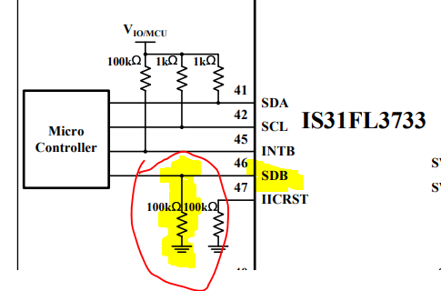
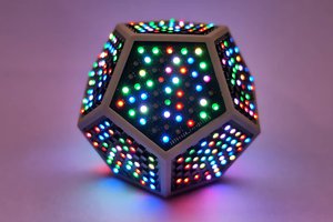
Thank you so much for sharing your findings with the shutdown pin - as I read it I had to immediately try it and voila, my pentagon shaped PCB now works! Thanks!

  Are you sure? yes | no

Similar Projects

Does this project spark your interest?

Become a member to follow this project and never miss any updates