 Alex Rich
I tested the idea of a single trigger without a nut to keep things simple, but I realized the pivot of the trigger was below where the trigger latched, meaning it could slip off on its own potentially. To eliminate this I went back to the idea of using a nut. The nut has a built-in lever so that I can easily reset it after firing. Below is the CAD process.
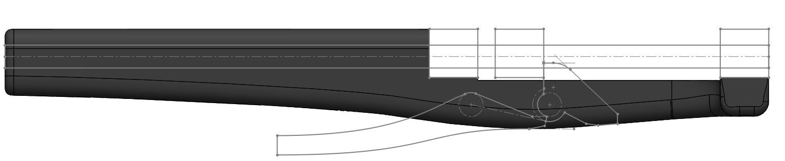
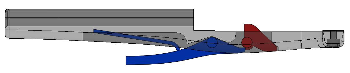
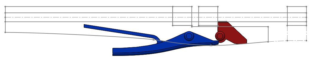
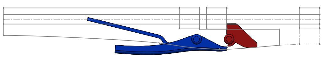
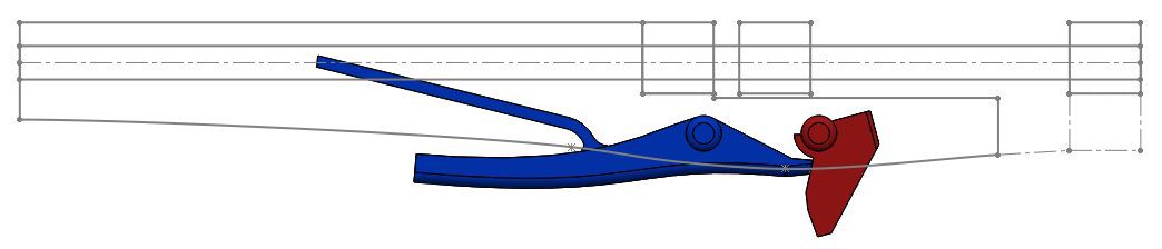
Step 1: Here is the side profile sketch I came up with after tinkering with it for a little bit.
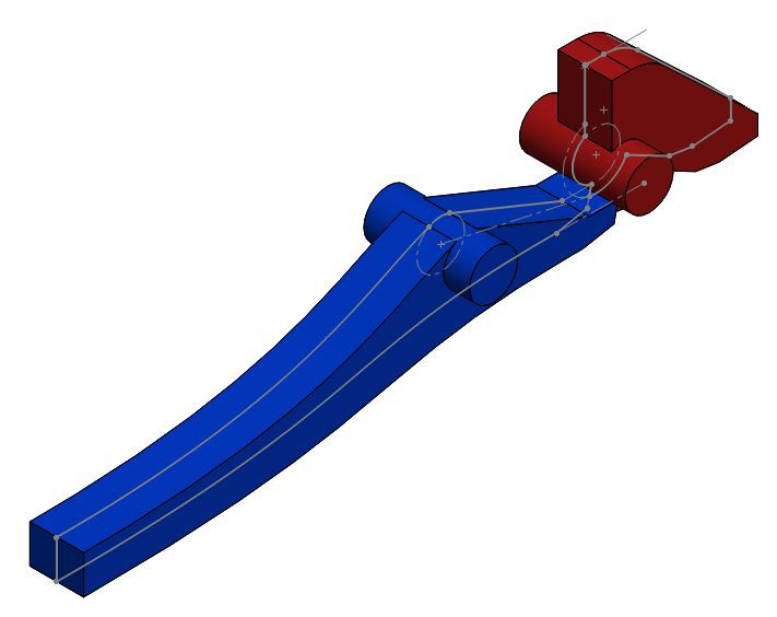
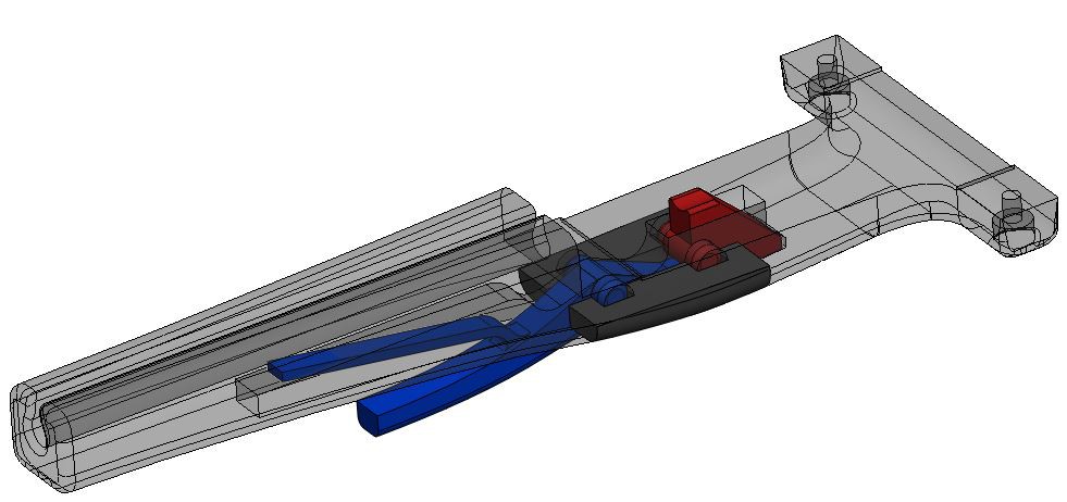
Step 2: Extrude the trigger (blue) and nut (red). Also extruded cylinders for the pivot points.
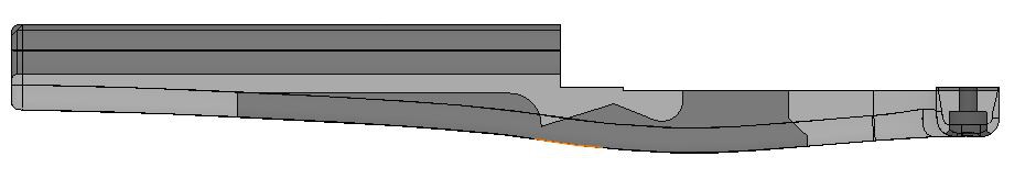
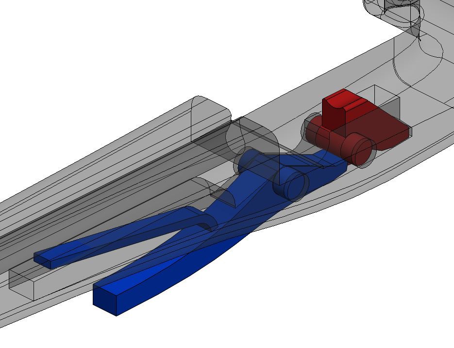
Step 4: Add a built-in return spring to the trigger, hopefully this won't just snap like a twig...
Step 5: Cut holes for the pins to rotate in
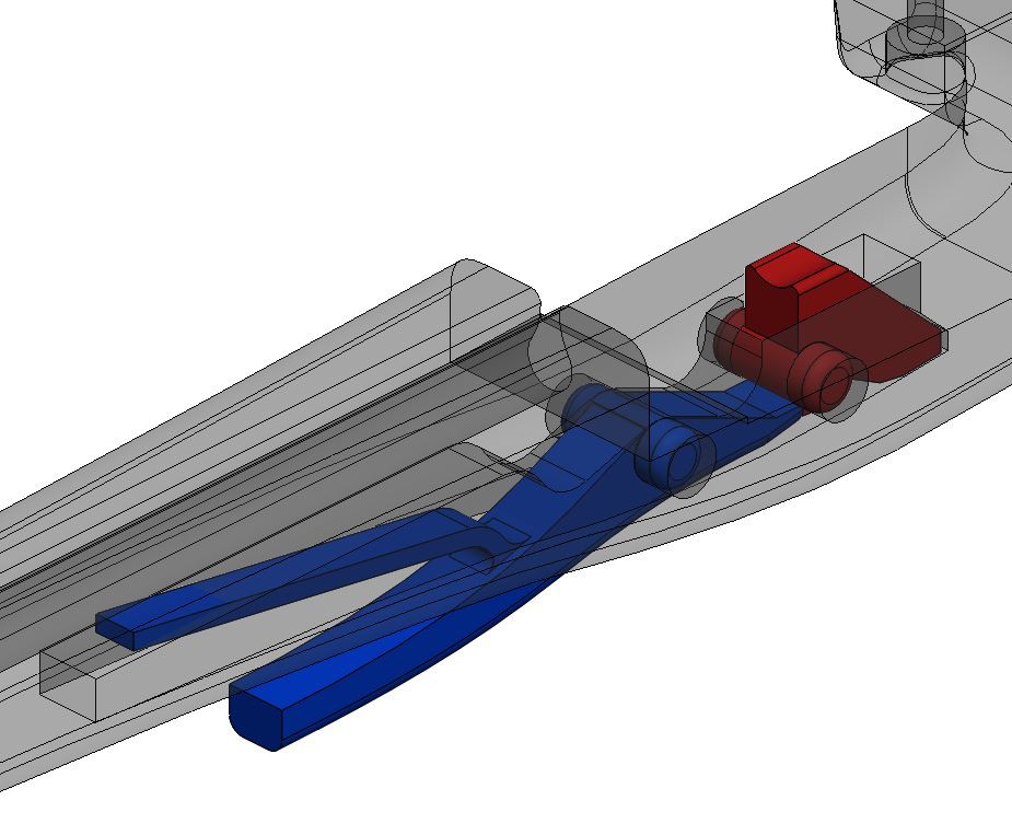
Step 6: Add fillets
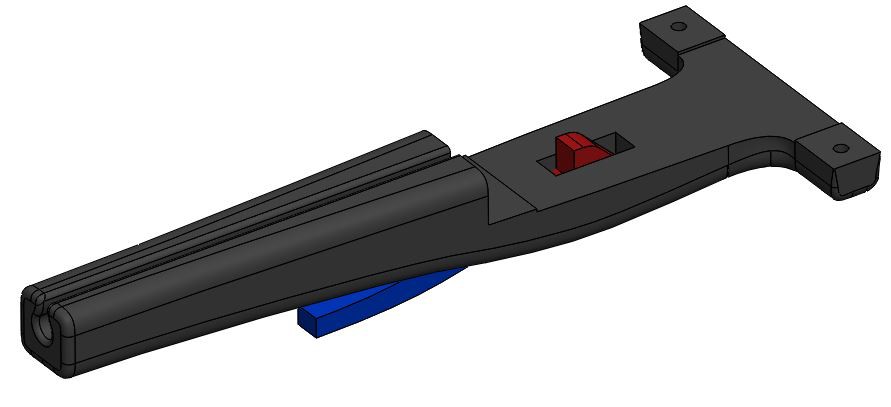
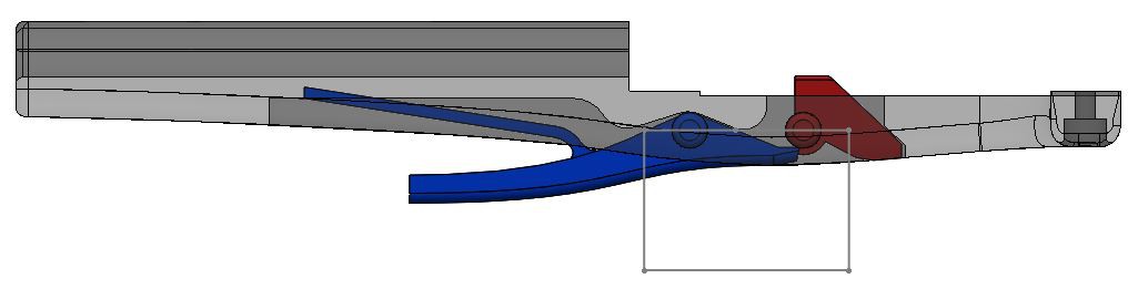
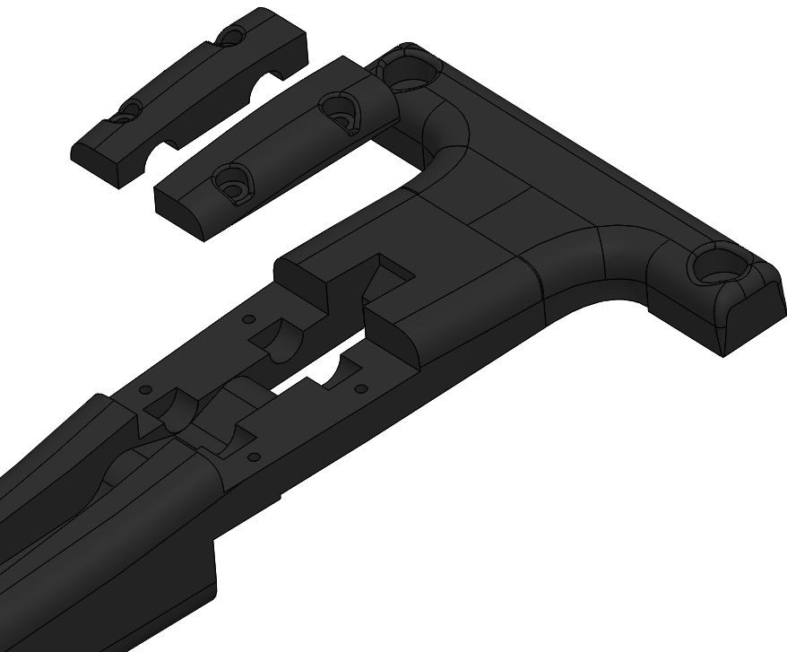
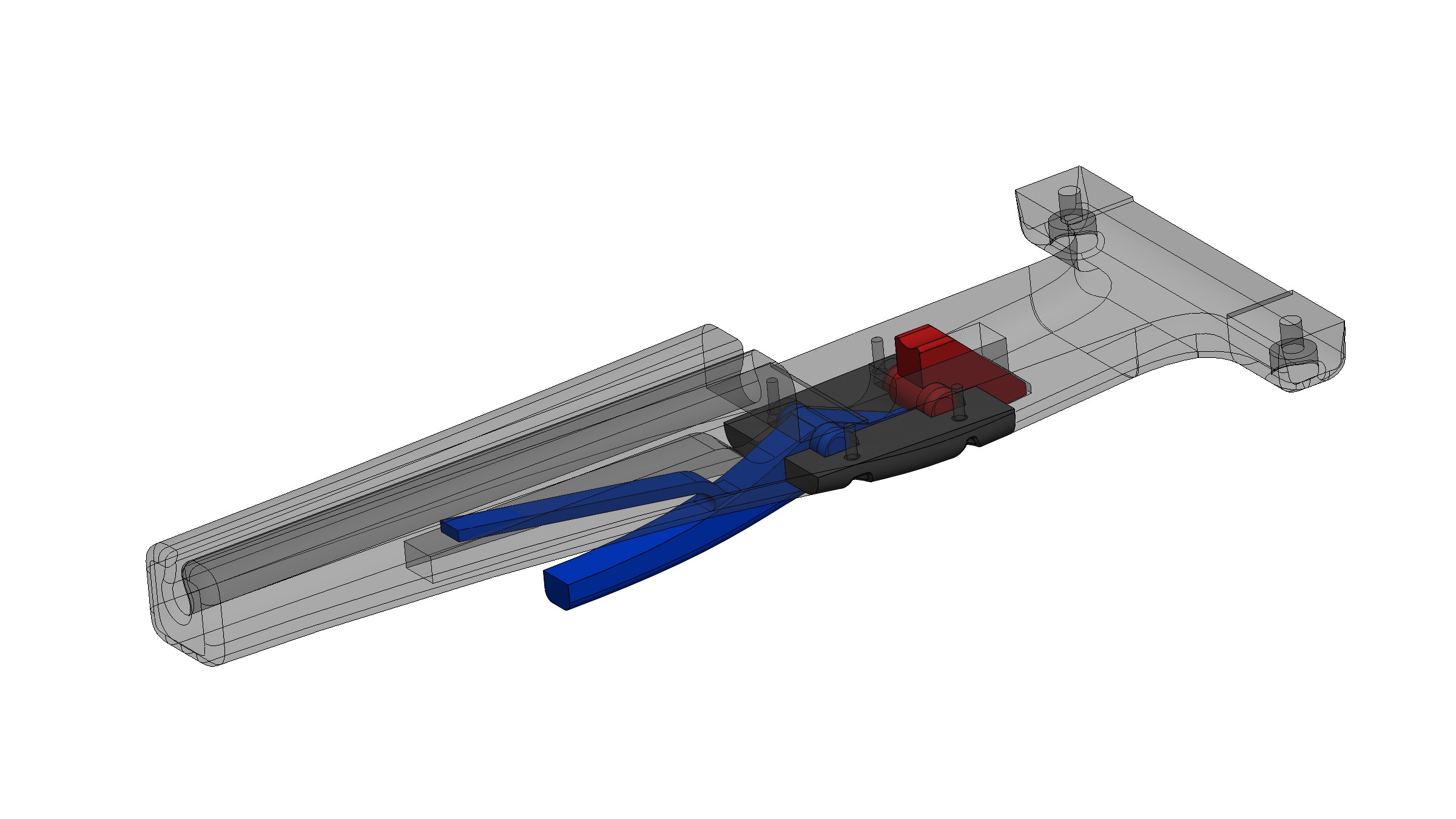
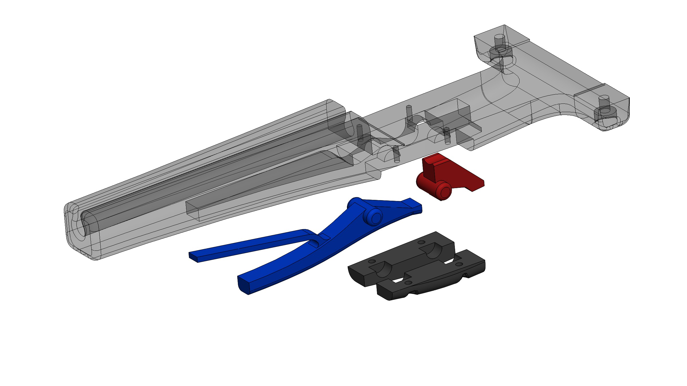
Step 7: In order to be able to assemble the trigger parts, I am going to split away two little pieces of the handle that will act as retaining plates. You can see the sketch and the finished split parts in the two pics below.
Discussions
Become a Hackaday.io Member
Create an account to leave a comment. Already have an account? Log In.
Good point about the too low pivot point and a nice solution with the new nut!
Are you sure? yes | no
thanks!
Are you sure? yes | no