 Hexabitz
What is it?
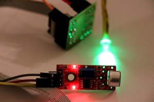
Four sensors/switches are connected to a single H05R00 module: Two mechanical limit switches, one optical endstop switch (used in 3d printers) and one magnetic switch (mechanical as well, usually used for doors etc.) This example particularly shows how the PortButtons BOS feature can be used for so many different implementations other than just read user buttons. We will be running two logs of different types simultaneously, one is rate-based and the other is event-based. Check the attached pictures and video .. Too many things to toggle lol :)
Components:
- 1 x H05R00 Hexabitz Micro-SD Memory Card Module
- 2 x Mechanical limit switch (NO)
- 1 x Optical lmit switch (NC)
- 1 x Magnetic switch (NO)
Estimated hardware build time: 5 minutes
Estimated software development time: 5-10 minutes
Code Description
The port switch/button functionality is a BOS (Bitz Operating System, the underlying Hexabitz backend) feature that converts array serial ports into I/O ports that can sample external switches via an easy-to-use API. In this example, we defined the four switches and associated each one with a different event.
AddPortButton(MOMENTARY_NO, P1);            // Magnetic
SetButtonEvents(P1, 0, 0, 1, 0, 0, 1, 0, 0);
AddPortButton(MOMENTARY_NO, P3);            // Limit Switch 1
SetButtonEvents(P3, 1, 0, 3, 0, 0, 0, 0, 0);
AddPortButton(MOMENTARY_NO, P4);            // Limit Switch 2
SetButtonEvents(P4, 1, 0, 3, 0, 0, 0, 0, 0);
AddPortButton(MOMENTARY_NC, P5);            // Optical
SetButtonEvents(P5, 1, 0, 1, 0, 0, 1, 0, 0);
The optical switch is bit different than the other ones. It is not a pure mechanical switch that connects and disconnects signals. The way BOS port button feature works is by outputting a 1 (3.3V) on port TXD pin and reading it back on RXD pin. If a mechanical switch connected these two lines together, it can be detected. The optical switch has 3 pins: power, ground and signal output. Nevertheless, I hacked it into a port button/switch by connecting its power pin to port TXD (the switch s 3.3V-5V compatible), its signal pin to port RXD and its ground to module GND. So basically it'll be powered for a short amount of time but it's enough to generate a signal and measure it. This works well because it's a simple switch with no delay or complications.
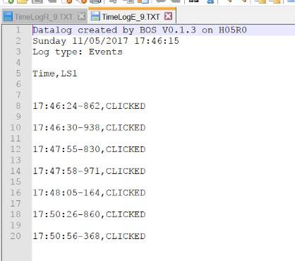
We create below an event-based log and log all the switches:
CreateLog("Event", EVENT, 10, FMT_COMMA, FMT_SAMPLE, "#");
LogVar("Event", PORT_BUTTON, P1, "Magnetic");
LogVar("Event", PORT_BUTTON, P3, "LS1");
LogVar("Event", PORT_BUTTON, P4, "LS2");
LogVar("Event", PORT_BUTTON, P5, "Optical");
Logging is then started and stopped after 30 seconds. The indicator LED is used to show some blinks!
IND_ON();

StartLog("Event");
Delay_s(30);
StopLog("Event");

IND_OFF();                // Signal the end of the log
Delay_ms(300); IND_blink(200);
Delay_ms(300); IND_blink(200);
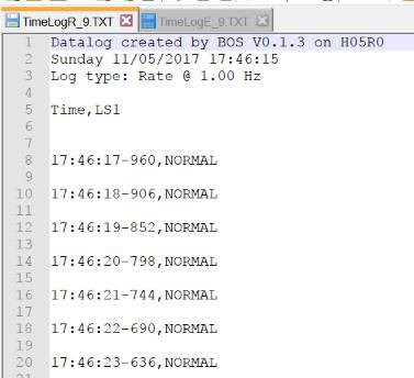
The event-based log can be easily replaced with a rate-based log as follows:
CreateLog("Rate", RATE, 10, FMT_SPACE, FMT_SAMPLE, "#");
You can also run both logs at the same time and start / stop them simultaneously or independently. Using the internal RTC and calendar available in all Hexabitz modules, you can setup a time-based log with time stamps as well. Check below for some screenshots of time-based logs. The demo code and example logs are attached to this project.

 Guy Dupont
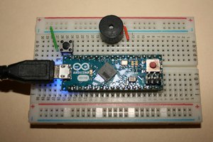
 The Lightning Stalker
 Łukasz Podkalicki