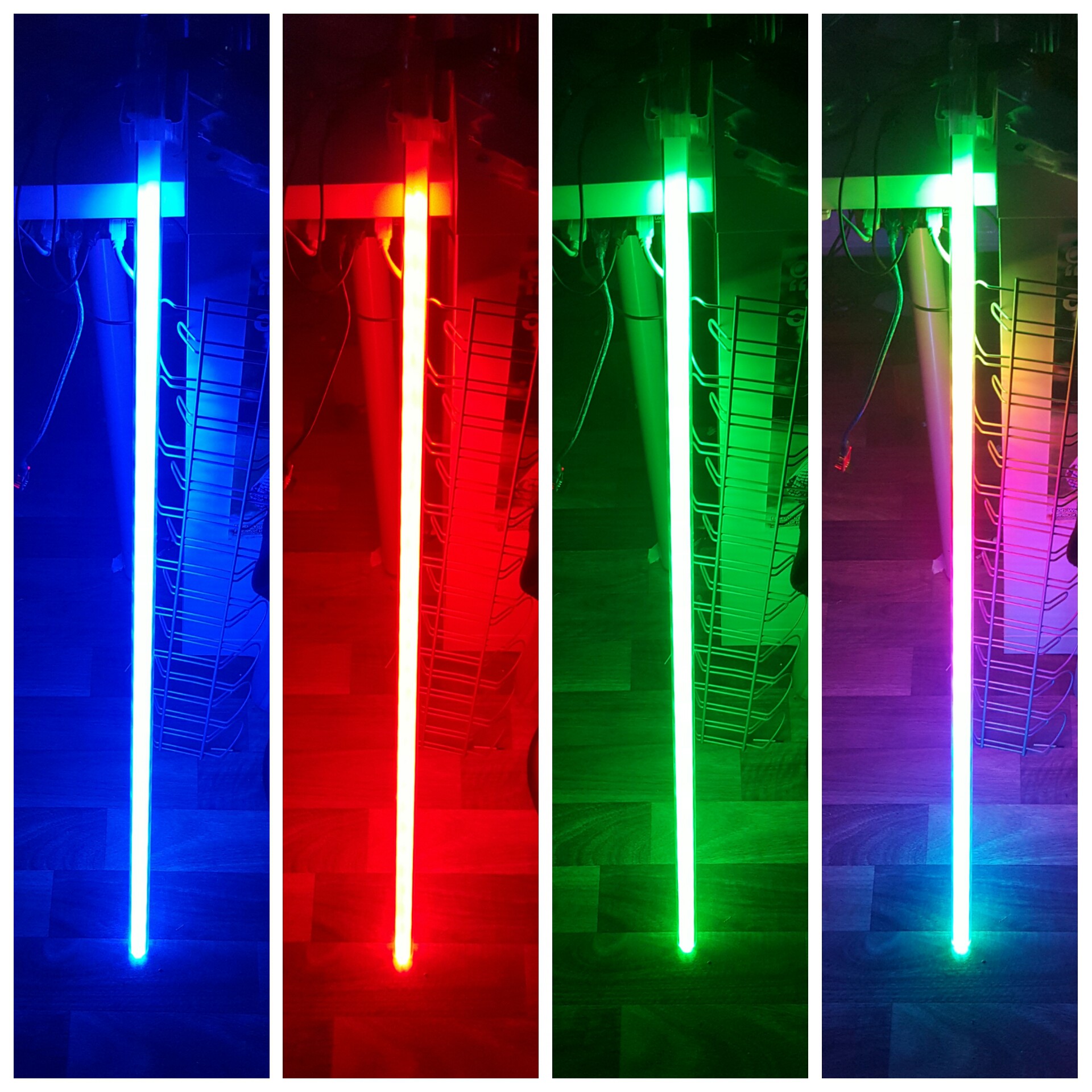
Since I couldn't find how to control it, here's my code how I did it. They probably focus on their python stuff more than on the Arduino IDE, which makes sense and all in all the Trinket still works with the Arduino IDE, so hurray :) You need to install the Adafruit_DotStar library, best done with the library installer. I had to change the datapin and clockpin, easy to find on the pinout site (https://learn.adafruit.com/adafruit-trinket-m0-circuitpython-arduino/pinouts. The other change I had to make was the configuration definition to BGR, RGB backwards. Now that I was able to do that, I found this https://forums.adafruit.com/viewtopic.php?f=25&t=124501&sid=21195cd2275abc7ba8a32912d47cff6f :D
// Simple strand test for Adafruit Dot Star RGB LED strip.// This is a basic diagnostic tool, NOT a graphics demo...helps confirm// correct wiring and tests each pixel's ability to display red, green// and blue and to forward data down the line. By limiting the number// and color of LEDs, it's reasonably safe to power a couple meters off// the Arduino's 5V pin. DON'T try that with other code!#include <Adafruit_DotStar.h>// Because conditional #includes don't work w/Arduino sketches...#include <SPI.h> // COMMENT OUT THIS LINE FOR GEMMA OR TRINKET//#include <avr/power.h> // ENABLE THIS LINE FOR GEMMA OR TRINKET#define NUMPIXELS 1 // Number of LEDs in strip// Here's how to control the LEDs from any two pins:#define DATAPIN 7#define CLOCKPIN 8
Adafruit_DotStar strip = Adafruit_DotStar(
NUMPIXELS, DATAPIN, CLOCKPIN, DOTSTAR_BGR);
// The last parameter is optional -- this is the color data order of the// DotStar strip, which has changed over time in different production runs.// Your code just uses R,G,B colors, the library then reassigns as needed.// Default is DOTSTAR_BRG, so change this if you have an earlier strip.// Hardware SPI is a little faster, but must be wired to specific pins// (Arduino Uno = pin 11 for data, 13 for clock, other boards are different).//Adafruit_DotStar strip = Adafruit_DotStar(NUMPIXELS, DOTSTAR_BRG);voidsetup(){
strip.begin(); // Initialize pins for output
strip.show(); // Turn all LEDs off ASAP
}
voidloop(){
strip.setPixelColor(0, 0xFF0000); // red
strip.show();
delay(1000);
strip.setPixelColor(0, 0x00FF00); // green
strip.show();
delay(1000);
strip.setPixelColor(0, 0x0000FF); // blue
strip.show();
delay(1000);
}
I was inspired by @deshipu to get an adafruit trinket M0 and redo the lightsaber with it, since the atsamd21 being used has a DAC on board and enough pins left to control some neopixels, check a button and grep stuff over I2C from the accelerometer. Just playing around with arduino and analog write I can say that it sounds so much better already.
There will be a connector involved for the neopixels and I want to make everything fit the acrylic pipe first, then redesign the 3D printed parts where needed.
Not exactly. What I did, previous to seeing your project and am still doing, is to average the total acceleration data and use this as a manipulator for the frequency generated by the tone() library. I based everything around a 50Hz wave and modulate everything to a deviance of 19Hz max. As I understood, you're manipulating the 555 circuit with your arduino? I still don't get your hardware design. Would be cool if you could share this as well and maybe a demo in form of a video showing your doppler effect.
Wow awesome project :) Just the right thing ;-)
Would you please do a longer video?
The 3D Modell is also a really nice job! *Thumb up*