 coon
coonThis is the smaller of the displays:
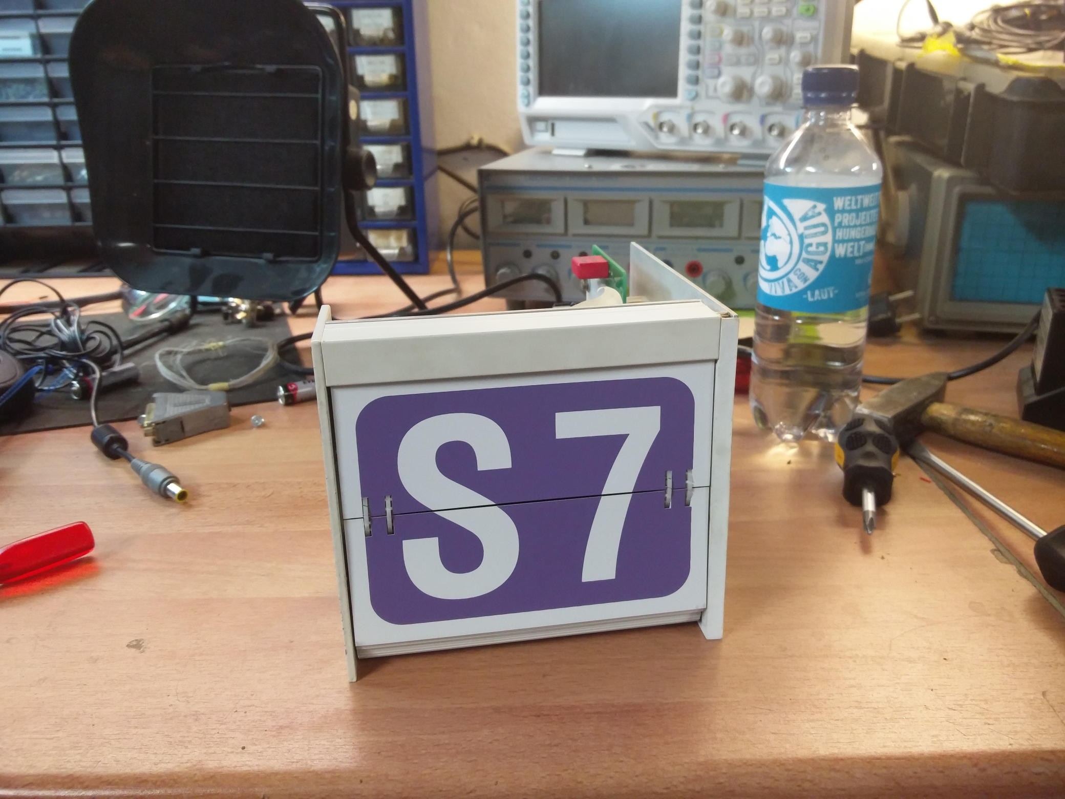
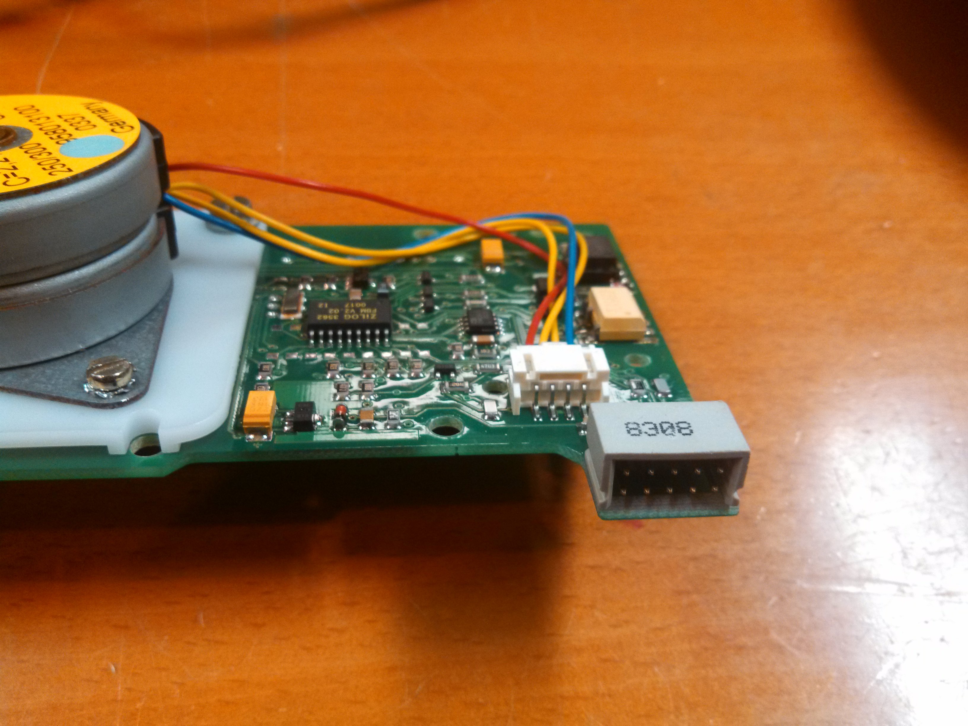
It consists of a roll of cards and a circuit board with a motor, which can flip the cards:
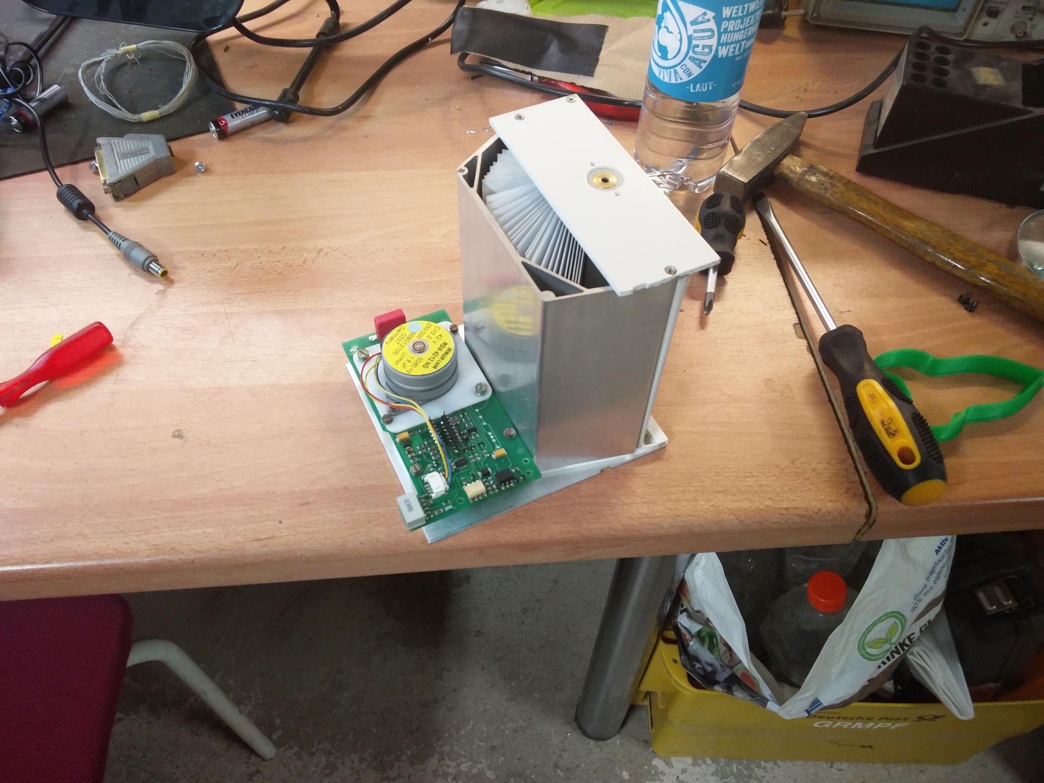
If you unscrew the board, you can see a gear. It is only possible to turn it in one direction. The thing which looks like a handle has a special function but more to that in a second:
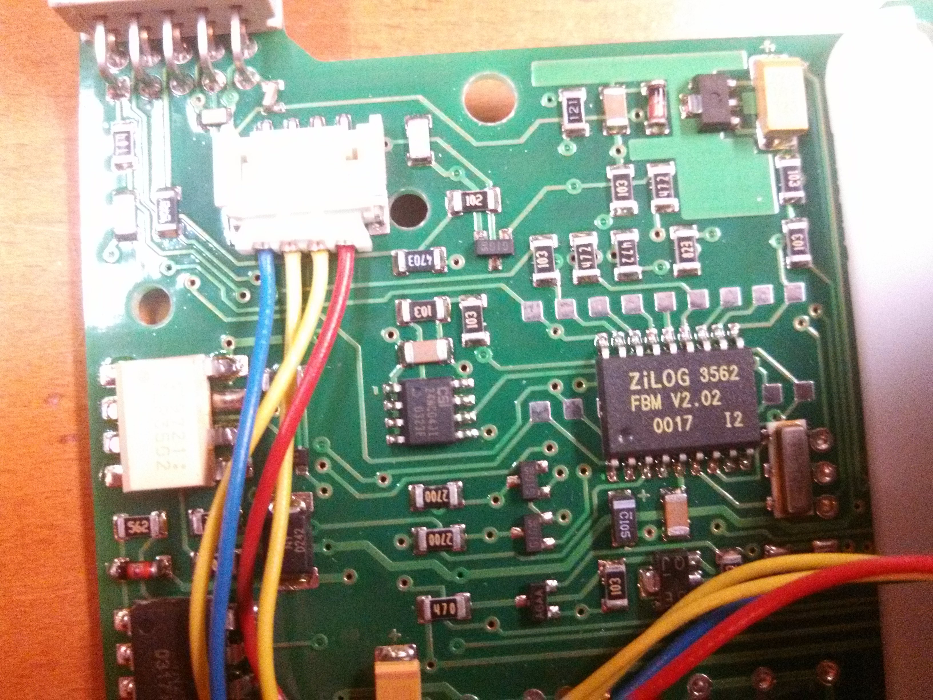
This is the controller board of the smaller display. It contains a Microcontroller, an I2C EEPROM, a motor, an optotriac and another opto coupler.
The motor is a synchronous motor which needs 42V AC.
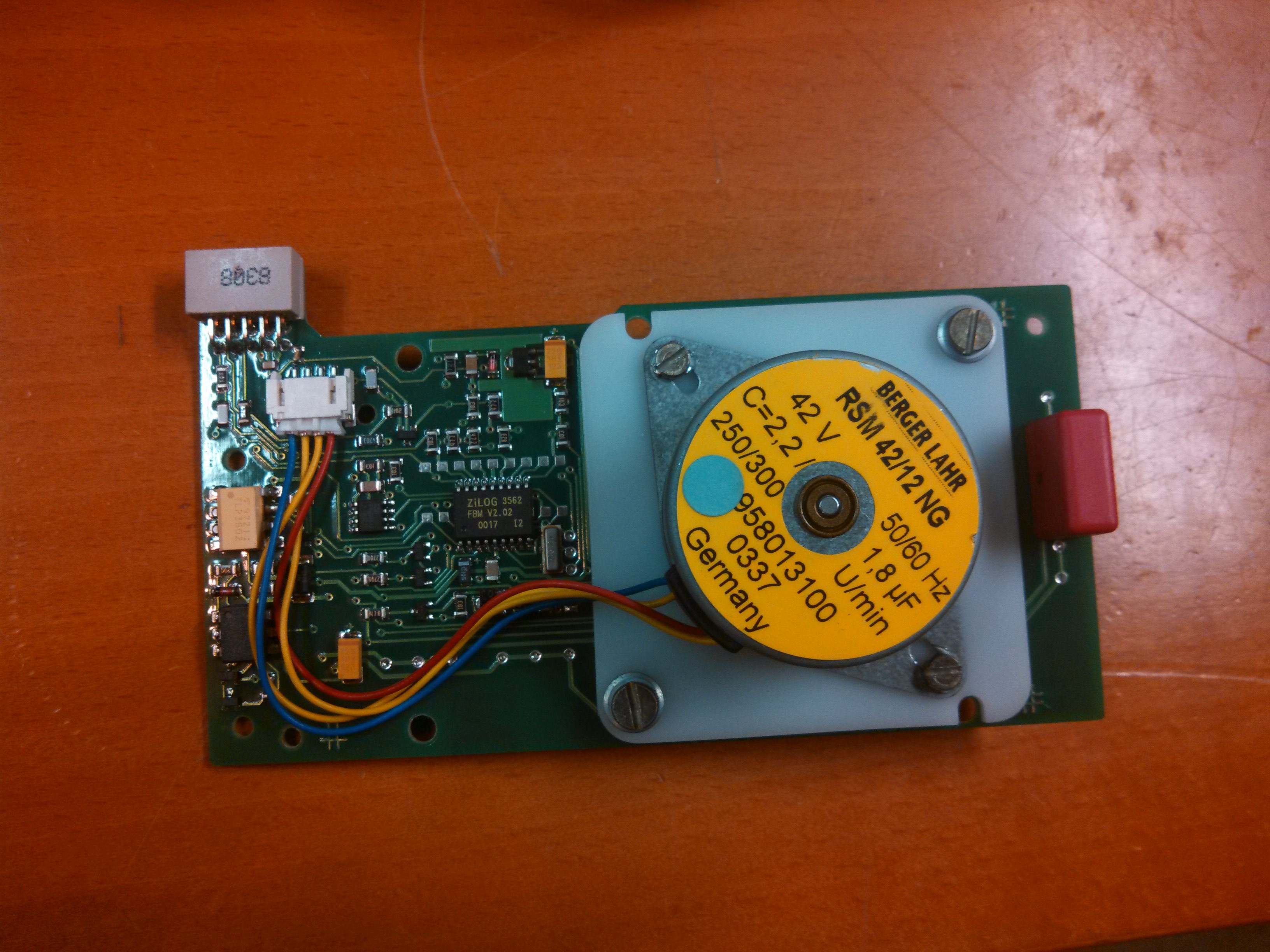
There is a Chip called "ZiLOG 3562 FBM V2.02". Unfortunately there is no datasheet for it on the web but it seems to be some kind of Z80 based thing. The SOIC-8 chip, on the left side from it, is a CSI 24WC04JI EEPROM which is accessed by using I2C. The two chips on the left are the already mentioned opto triac (white) and the opto coupler (black).
On the edge of the board is a 10 pin connector. It is connected to another board with a shift register and a DIP-Switch, where the device address can be set. Also the power supply is provided over that connector.
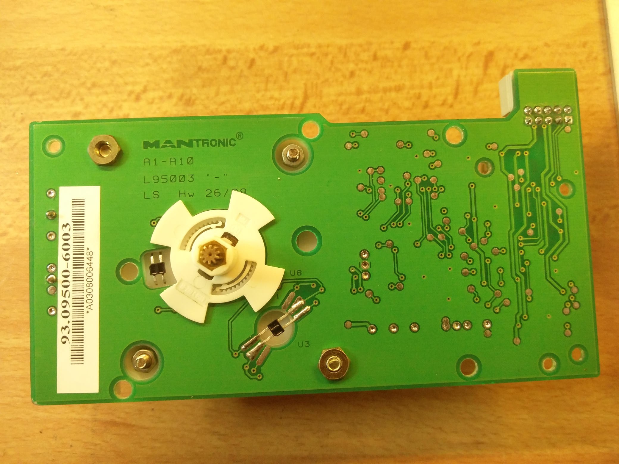
On the back side of the board you can see a rotary encoder and two infrared transceivers. The microcontroller uses them so it knows which card it is currently displaying.
One infrared transceiver consists of an infrared LED and an infrared receiver. It is an analog signal. The more light the sensor hits, the higher the voltage is. Always, when a rotary encoders blade is over a sensor, the infrared light will be reflected on it so there will be a logical 1: [oszi bild hier enfügen]
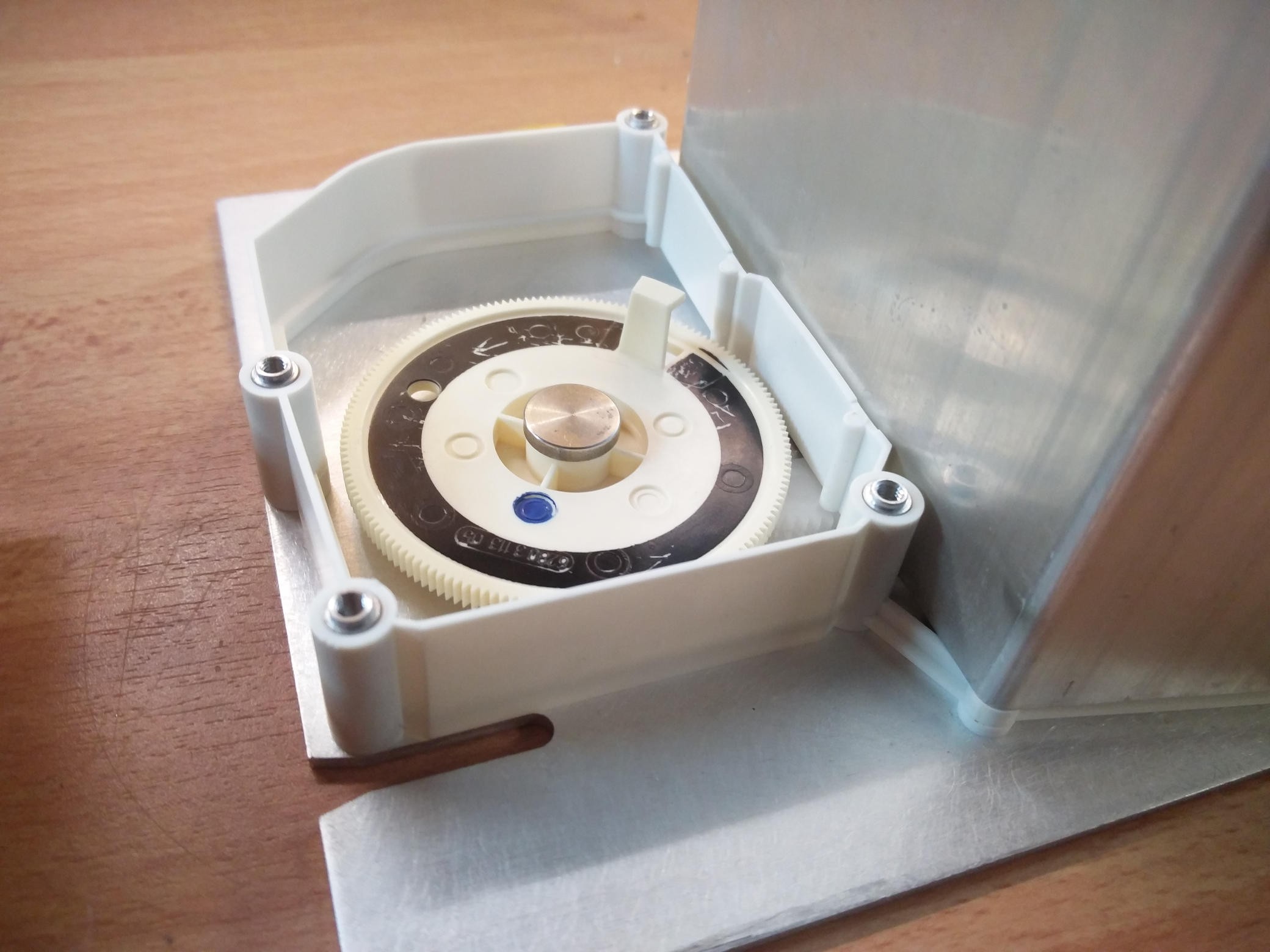
The other lonely sensor is used to find out where the beginning of the card set is. It is mounted right above the gear we did already see in an earlier picture:
As you can see, there is a black circle which is interupted by the handle. The handle has white color, so the infrared light will reflect here and marks the beginning of the cards.
 Torbjörn Lindholm
 M.daSilva
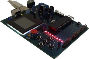
 Andrei D.
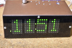
 Bharbour