 M.daSilva
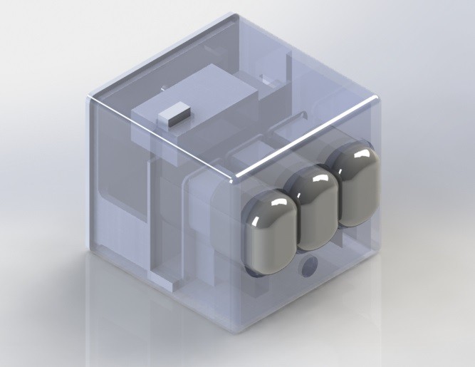
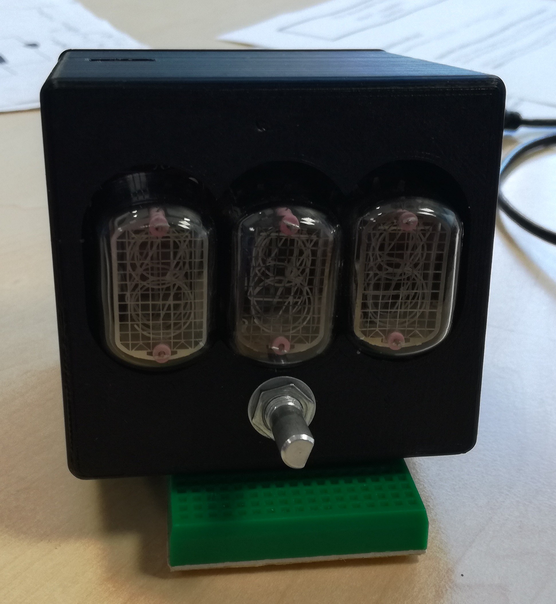
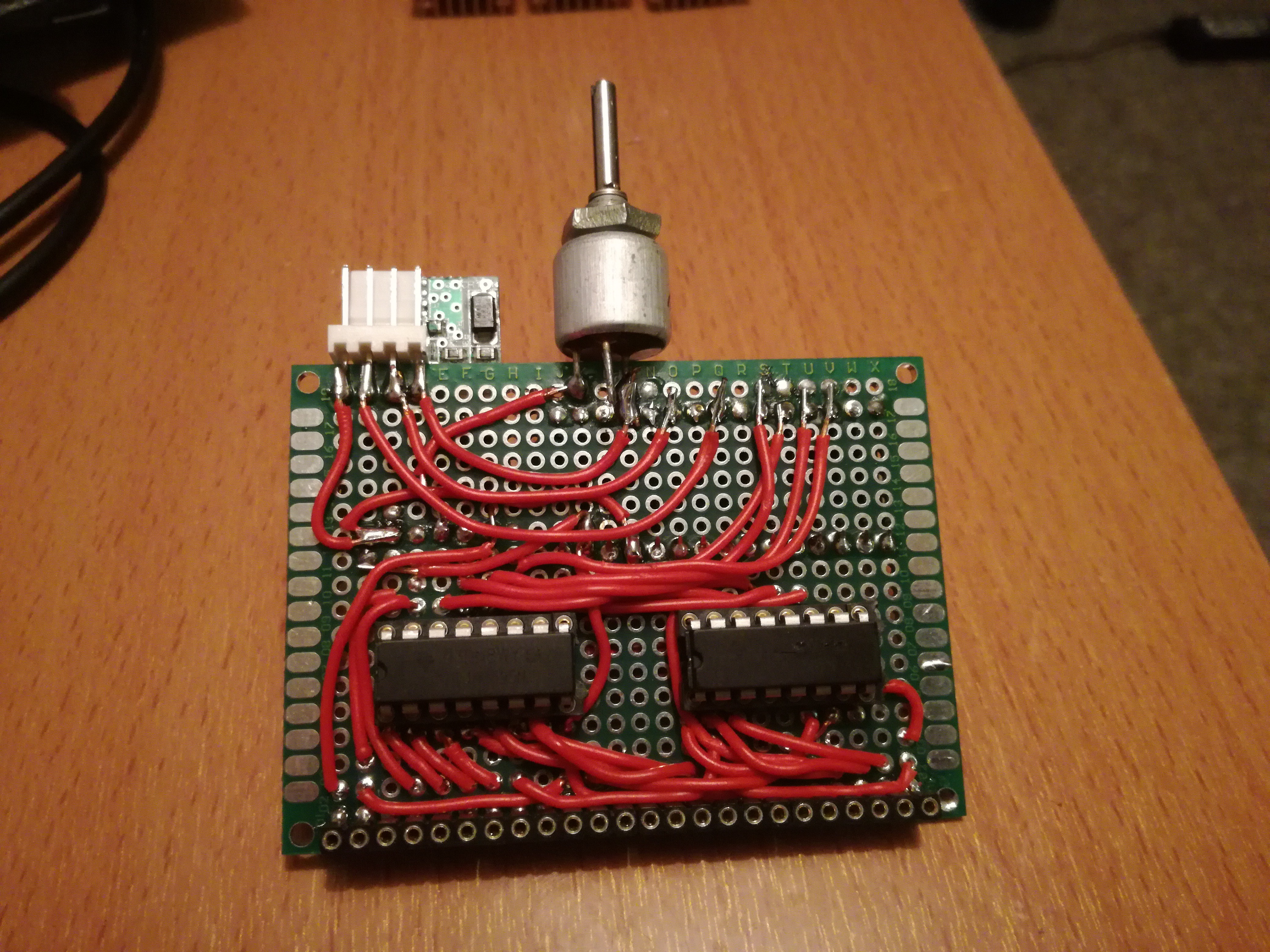
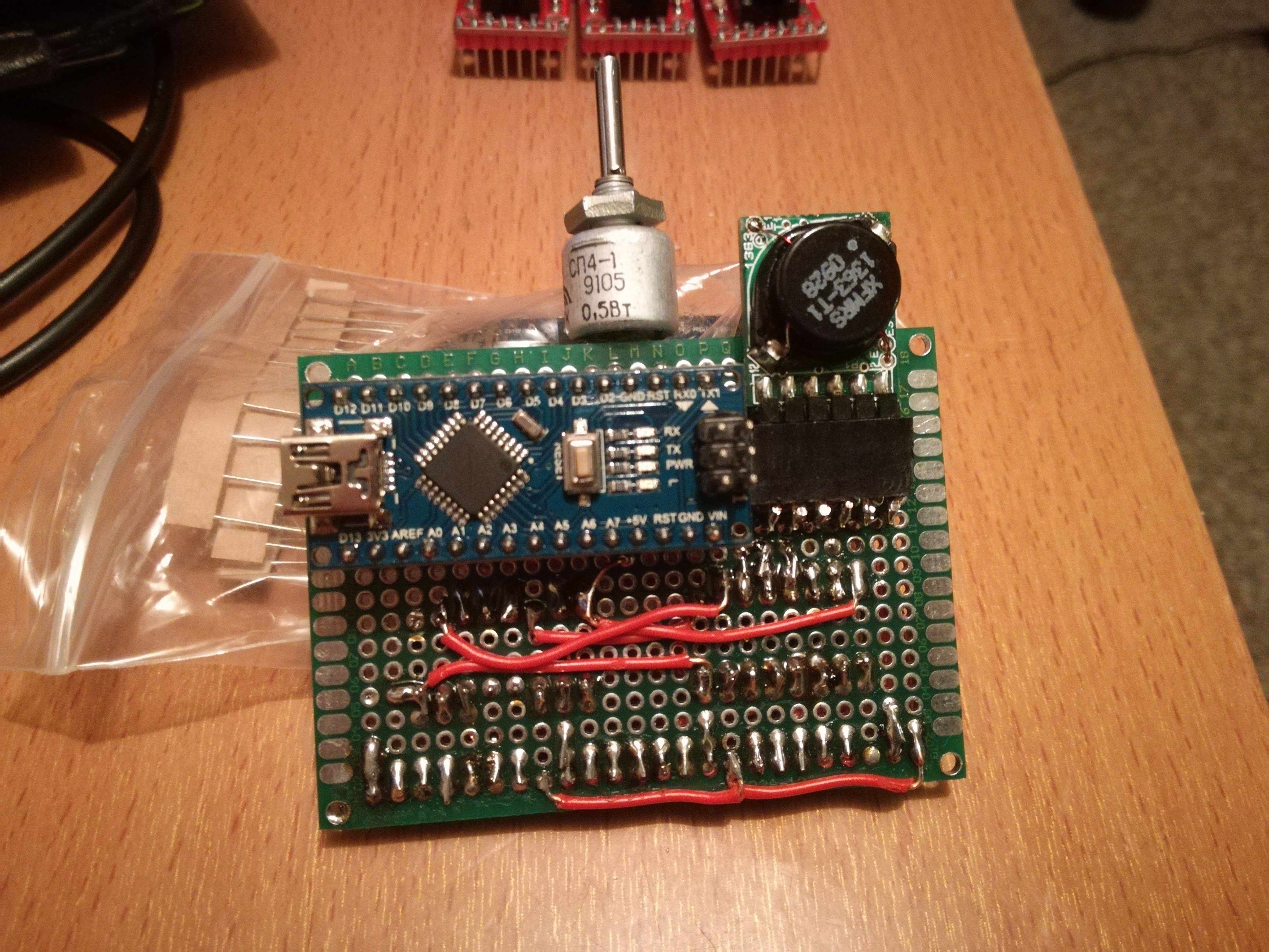
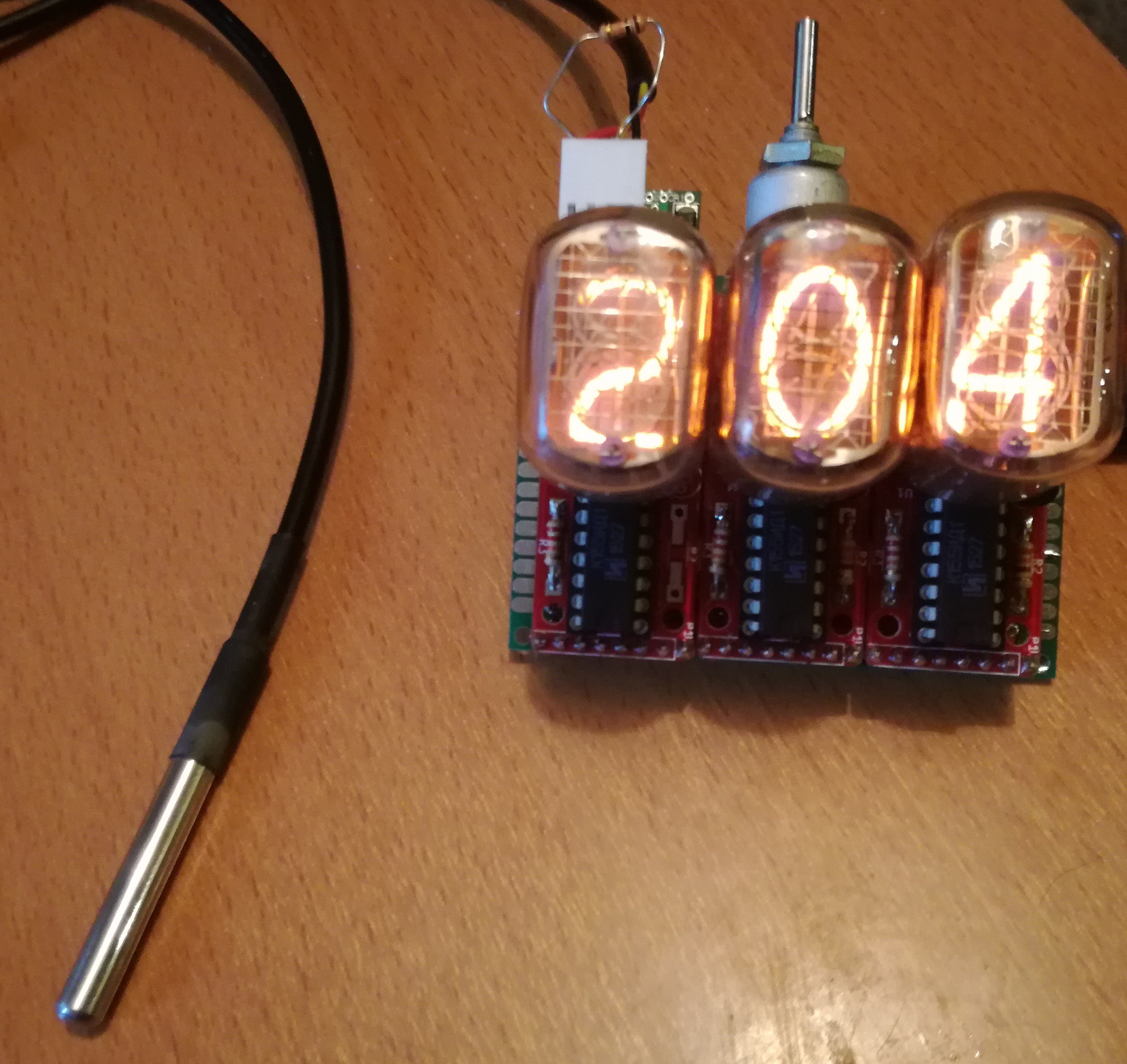
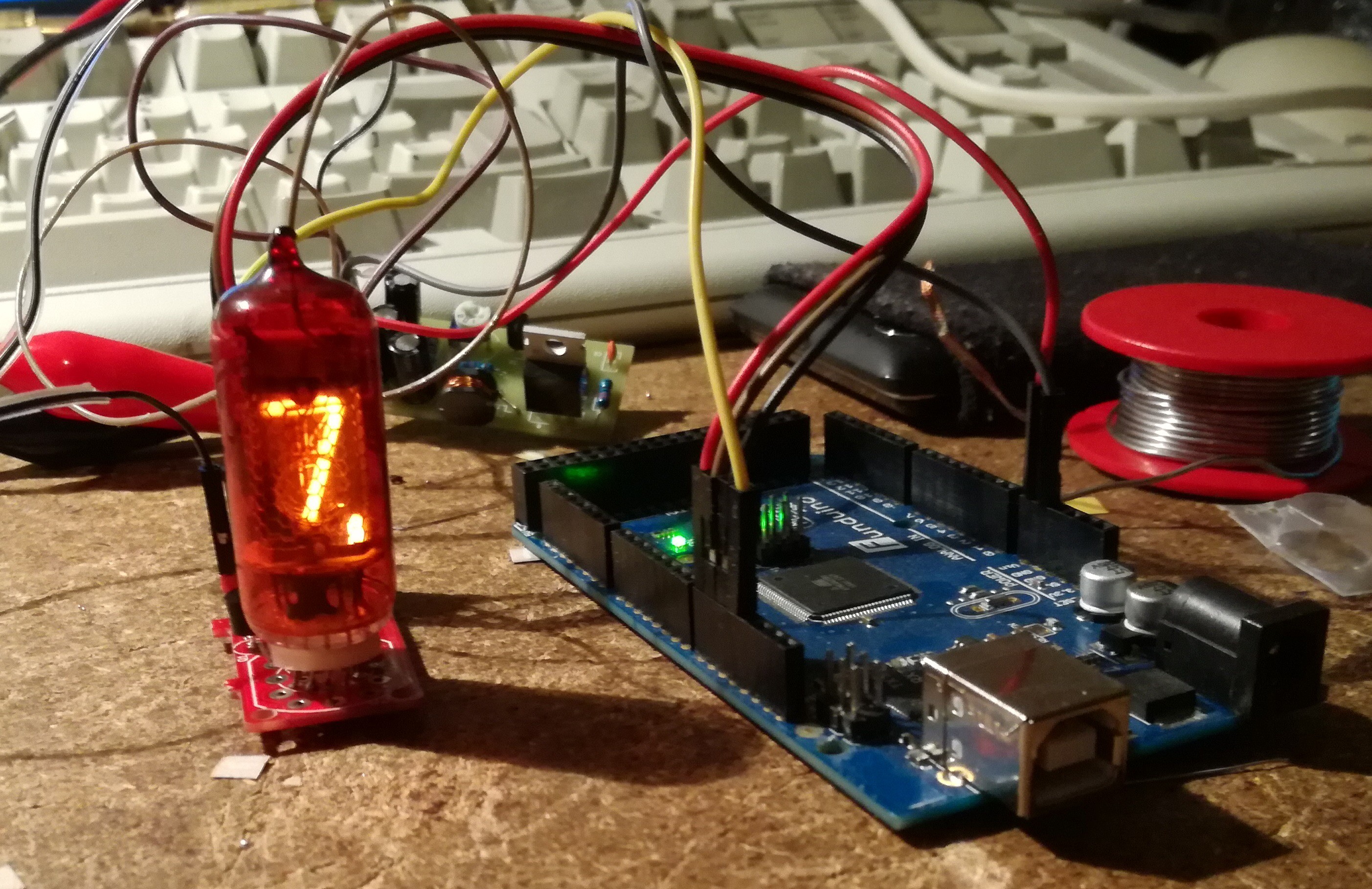
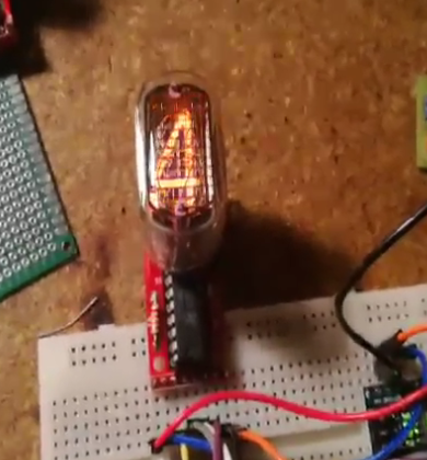
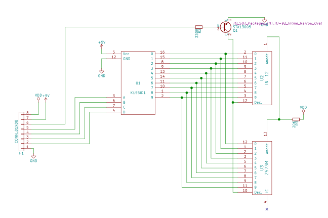
The display includes a small high voltage power supply, an Arduino-type microcontroller, a couple of shift registers and three IN-12 nixie tubes.
A 4-pin connector breaks out power, ground, and two data lines for interfacing sensors with the microcontroller.
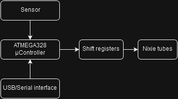
The user interface consists of a simple rotary encoder (with a pushbutton).
Two sensors are being used right now:
-Speedometer (with a GPS receiver)
-Thermometer (with a DS18B20 sensor)

 Dimitar
 Arduino Enigma
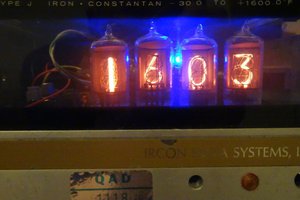
 Ken Yap
 doctek
Nice project ! I made a digital clock using 4 x IN-16 nixie tubes. In my case, it operated by anode current 1.1mA for 3 years continuously now.