

 M.daSilva
 Benchoff
 Tindie
 Aleksandar Bradic
 Arya
Arya deʃhipu
-
Custom battery packs, ugly spot welder
09/07/2017 at 13:18 • 0 commentsI needed a 7.2V battery pack for an ongoing project. Too lazy to go and buy pre-made packs, I made my own.
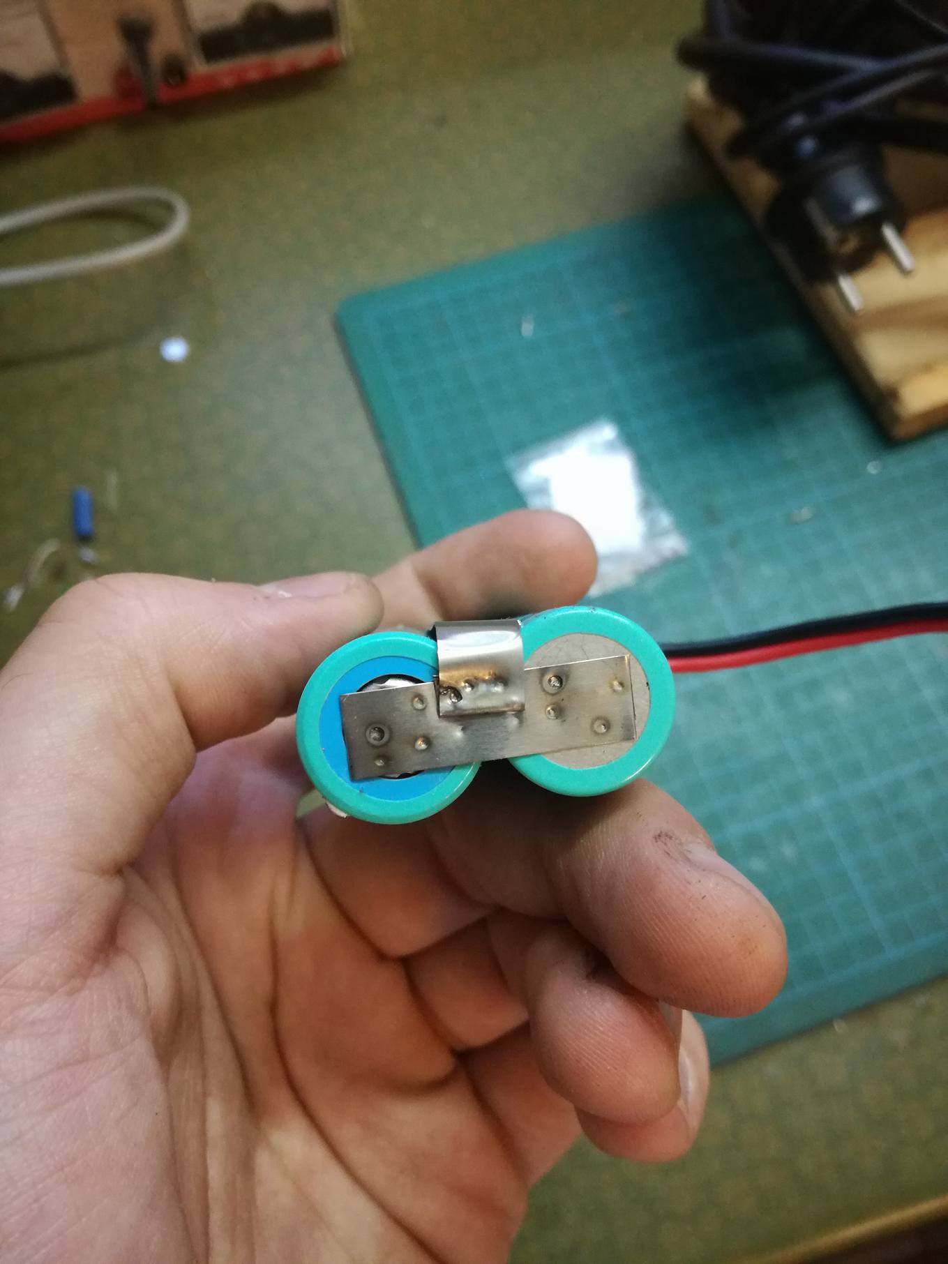
The cells are bog-standard Lithium-ion 18650s recovered from laptop battery packs. I cycled them twice with an Accucel charger to check the capacity. Surprisingly enough, they still had 80% of their original rating, after more than 7 years! (we'll see how it evolves over time...). So, 7.2V, that means two of them have to be connected in series.
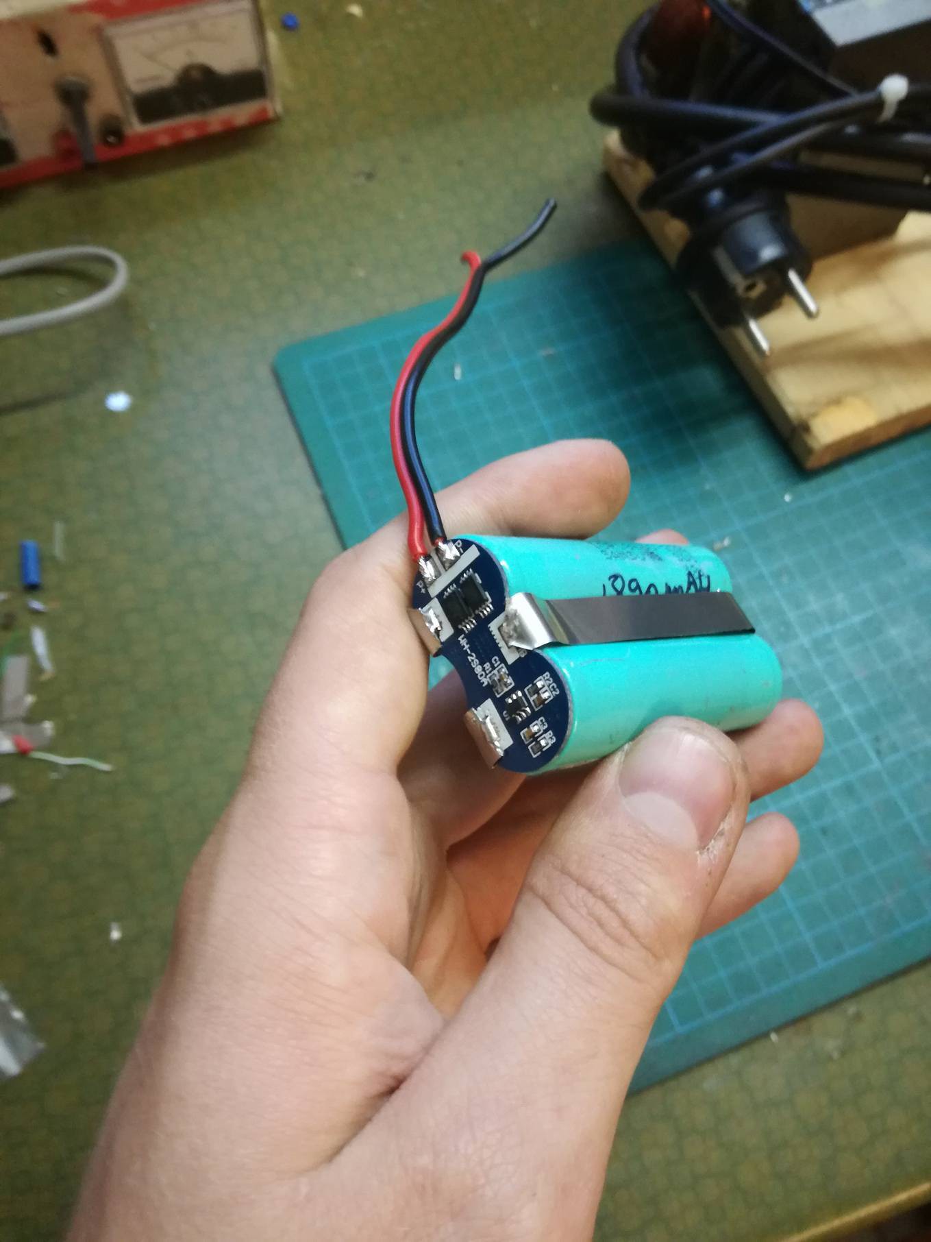
Now, those packs need some extra care: you have to protect them against deep discharge, overcurrent, overcharging, and you also have to balance the individual cells. Luckily, you can find separate protection circuits on eBay, sometimes for less than $2!
![]()
Hooking them up is a project in itself. I didn't feel safe heating the battery terminals up to 350°C in order to solder wires directly to them. Besides, they're a royal pain when it comes to tinning those big, heat-sinking terminals. I thus spot-welded them, as they were originally intended to be. My technique is still far from perfect, it's the first time I did such a thing.
![]()
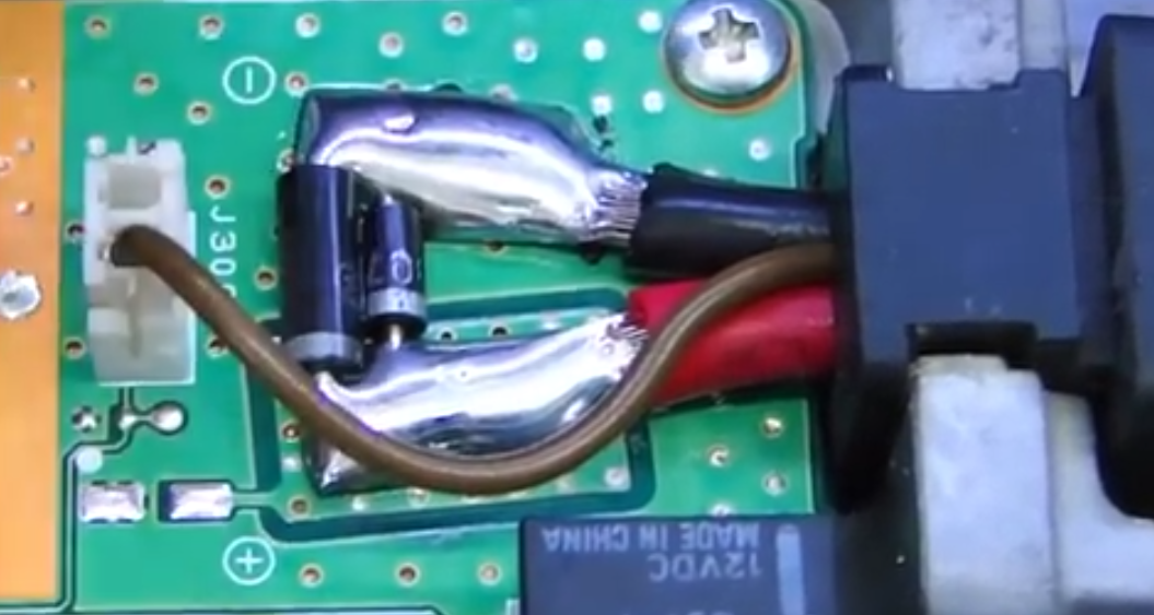
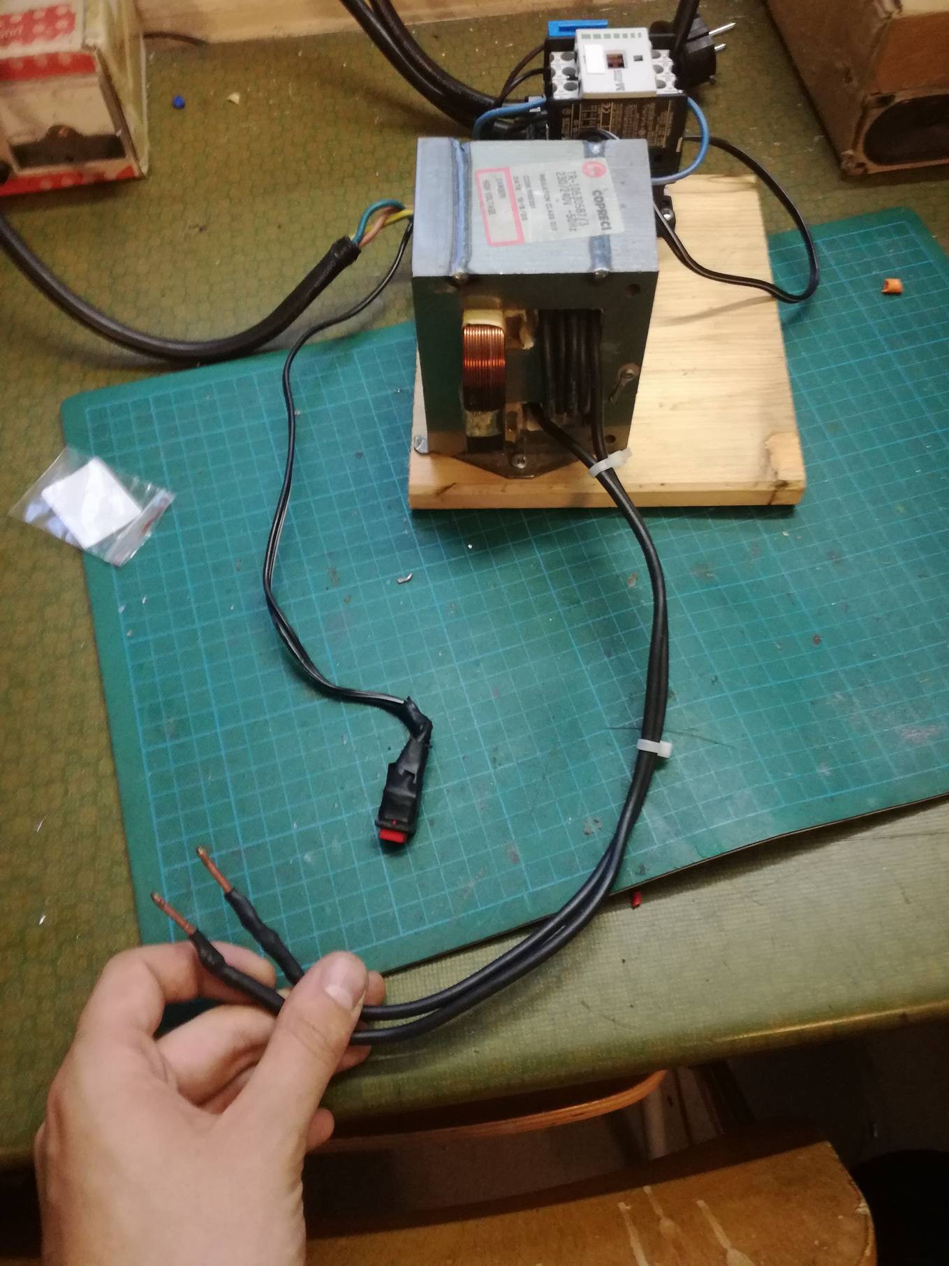
The spot welder is also home-made: it's an old microwave oven transformer whose 2kV secondary winding has been sawed off, and replaced by a few turns of low gauge wire. The electrodes are also made of a single core, low gauge piece of wire, with filed, sharp tips. The primary winding is wired straight into the 230V mains, through a big DIN relay, itself switched by a small handheld button. I still have to build a holder for the electrodes (and maybe make them a tad bigger, they tend to heat up)... But it works! I'm still waiting on the heatshrink tubing to protect the finished packs.
![]()
This can of course be scaled up to any battery size, rating, voltage, etc... You can find protection circuits for Lithium batteries on eBay from 1 to 14 cells, and up!
-
First adventures in the CNC milling world
05/03/2017 at 11:37 • 0 commentsNothing I though worth writing a entire project about, it's a project I did last year, to get my feet wet with metal CNC milling.
I built a Bluetooth speaker with cheapo eBay modules: Bluetooth audio module, audio amplifier, USB charger, boost converter, and a recovered Lithium-ion battery from a laptop.About 10€ in parts altogether.
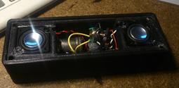
The main case was 3D printed, and some hot glue was involved.
The lid had to be done, and I had an opportunity to use an Arrow 500 CNC mill... A small machine :p
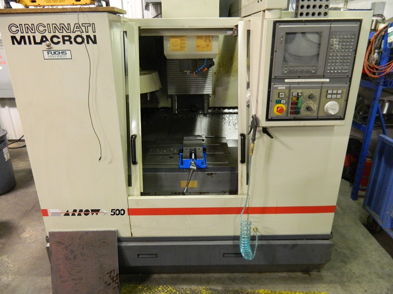
Aluminium it is then!
A quick modelling and schematic was carried out on Solidworks (dimensions in non-freedom units):
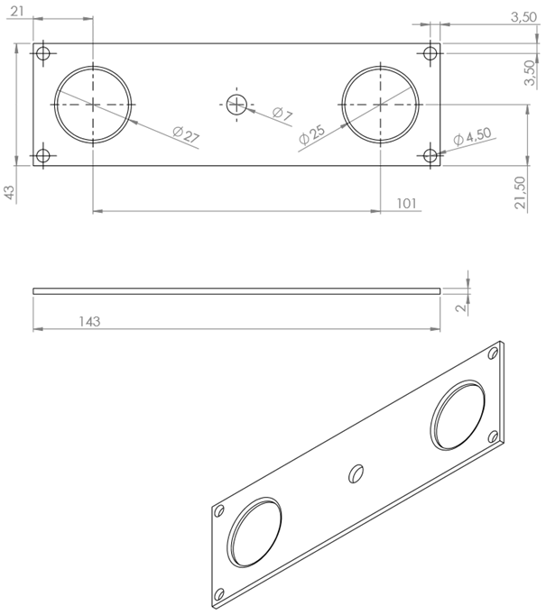
I quickly printed it out to check the fit with the case.
The G-code was hand-typed, I used CIMCO to carry out the simulations before using the real thing.
G40 G17 G90 G54 G94
T3 M6 '(4mm mill)
G0 G43 H3 Z50 '(tool compensation, high axis speed)
G0 G94 S6000 M3 '(mill motor start, clockwise)
'(4 mounting holes)
G0 X3.5 Y3.5 Z2 M8 '(bring the tool closer to the part, start coolant)
G1 F50 Z-4
G1 Z10
G0 X139.5 Y3.5 Z2
G1 Z-4
G1 Z10
G0 X3.5 Y39.5 Z2
G1 Z-4
G1 Z10
G0 X139.5 Y39.5 Z2
G1 Z-4
G1 Z10
'(central switch hole)
G0 Z50
T7 M6
G0 G43 H7 Z50
G0 G94 S6000 M3
G0 Z2 X71.5 Y21.5 M8
G1 F83 Z-4
G1 Z10
'(speaker holes)
G0 Z50
T3 M6
G00 G43 H3 Z50
S6000 M3
G0 X21 Y21.5 Z2 M8
G1 X21 Y21.5 F140 G40
G176 X21 Y21.5 Z-4 R10 D3 E100 K6 Q13.5 P30
G1 Z2
G0 X122 Y21.5 Z2 M8
G1 X122 Y21.5 F140 G40
G176 X122 Y21.5 Z-4 R10 D3 E100 K6 Q13.5 P30
G1 Z2
'(final plate cutout)
G0 Z50
T5 M6
G00 G43 H5 Z50
S5406 M3
G0 Z10 X0 Y0
G0 Z2
G1 X0 Y0 G42 D5
G1 F60 Z-4
G1 F180 G42 D5 X143 Y0
G1 X143 Y43
G1 X0 Y43
G1 X0 Y-2
'(program end)
G1 Z10 M9
G0 Z50
G0 Z50
T0 M6
M30
As you can see, the program was split up in four sections:- Mounting holes with a 3mm mill;
- Central hole for the switch;
- The two pockets for the speakers;
- The final cutout.
The code is fairly standard, G1s were used for straight cuts/holes. The only exotic one is the G176, which is used to mill out the pockets for the speaker holes.
After simulation on CIMCO (which is, BTW, incredibly expensive... The interface still looks like an MS-DOS prompt, even through it's a 2015 software!), the code was transferred over to the Mill (which is a genuine DOS machine, also a royal PITA to operate). Lots of small tweaks had to be done, the holes weren't correctly centered, tool compensation was off, ...
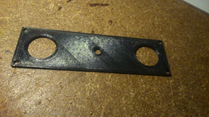
I cut the part off a 4mm aluminum painted plate.
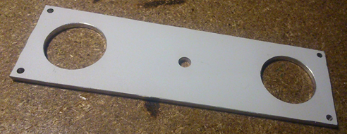
After lots of sanding, it was finally mounted onto the speaker.
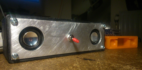
And voilà! :)
Now, there are a few things I could've done better here:
- Use a thinner plate, 2mm would've been plenty enough. However, that was the only thing I had at the time;
- The final cutout is irregular: you can see where the mill started the cut;
- I could've sped up the cycle by getting the mill closer to the plate whenever I needed the G0 cycle (I basically backed the mill 50mm out at extremely low speeds before G0s).
This could've taken waaay less time on a manual mill, or even with a bandsaw, a drill press and some files, but it sure was a fun and an interesting way to learn how to manually write G code!
-
Reverse polarity protection on preexisting equipment
03/15/2017 at 23:48 • 0 commentsYes, I know, this is electronics 101, this was written for personal reference.
I'm using radio transceivers in all kind of conditions, including portable, where you sometimes have to wire the power supply in a hurry. I never got it in reverse, but I fear this may happen one day. As this kind of equipment can be quite costly, such a mistake can have quite catastrophic consequences.
I'll take the example of one of my radios, the Yaesu FT-857. Very nice piece of kit, although the power amp transistors are directly connected to the power rail. One mistake, and they're blown (along with other, costly components). There are a few ways to avoid this, two of them being extremely simple:
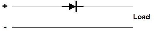
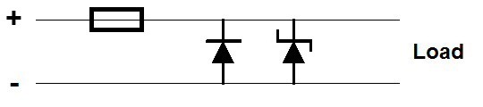
- A diode in series with the power line: it conducts in the "right way", and blocks off any current in the other direction. This is nice and all, but there's the diode drop! It wouldn't have been an issue if the current was low enough, but we're talking about 25A! For a typical 0.6V diode drop, that's 15W of power dissipated by that poor semiconductor.
- A diode in parallel with the power line. It doesn't conduct in the "right way". If the polarity is reversed, the diode starts conducting, drawing a huge current. As my radios always have an inline fuse, it blows, instead of destroying the equipment. I like this idea better: no power loss, the only downside being you have to replace a fuse everytime you mess your wiring up. As this is a last resort protection measure and you should be careful anyway, this shouldn't happen very often, should it? A simple 5A rectifying diode should do the trick.
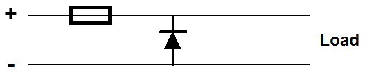
We can add overvoltage protection with a carefully chosen Zener diode wired in parallel. As this radio shouldn't take more than 13.8V+10%, 15.18V, I'll pick a 15V 5W Zener, the 1N5352B. If the voltage goes over that value, once again, the diode conducts, drawing a high current, and (hopefully) blowing the fuse.
I don't have access to this kind if diodes right now, but here's an example of such a mod by Alpha-Telecom (brazilian YT channel, only thing he does is fix HF transceivers. I highly recommend it if you speak Portuguese) here. The diodes are directly soldered to the power supply cables.
This is an extremely simple and cheap mod, which can be done for all sorts of equipments and can save their lives!
My Projects
My Pages
Things I've Built
Battery box
For all your powering needs! Includes 20Ah of SLA batteries, a 5V 1A regulator plus a 220V converter. Everything in an sealed ammo box.
50W Beam Light
With a 50W LED module, a boost power supply and a LiPo battery.
433MHz Beacon
Using an ATTiny microcontroller and a radio module, I built small trackers that could be included in model rockets, and then tracked down using a directional antenna. I actually used this in my Rocket Data Logger (see project page).
Bluetooth Speakers
3D printed case, CNC milled face plate, battery salvaged from a laptop. Mainly just a pretext to play with the school's CNC mill.
Raspberry Pi Car Sound Effects
Using a Raspberry Pi and some buttons, I made a V8 sound machine for a huge parade bicycle we made in a shape of a big Hummer. We actually won a prize with that!
Rocket Engines
Sugar and KNO3, but pretty much each and everyone blew up.
Wooden Boombox
Goes back a looong time! I threw that together using some perfboards, TDA2003's, car speakers and a nice painted wooden box!
Power Supplies
Nothing too special, Nixie PSUs, Flyback Drivers, ...
Supercap Charger
A small, automated supercapacitor charger, using a microcontroller to monitor the voltage, a car relay and an analog dial for setting the voltage. I may do a project page someday...
Hybrid tube amp
Based on that design: http://diyaudioprojects.com/Solid/12AU7-IRF510-LM317-Headamp/ I still have to make a nice case for it!
 f4hdk
f4hdk MakersBox
 Voja Antonic
 Evan
Evan techknight
 Norbert Heinz
 Alex Lungu
 Mark Howe
 Nick Poole
 Frédéric Druppel
 Hobby Hoarder
 Stefan Köhler
 Mike Rigsby
 Greg Zumwalt
 Nick Rehm
Thanks for following, #Bendertech nice !