-
Drive that passive rail
03/19/2016 at 05:28 • 2 commentsSince we launched the project nearly every nay sayer has the same feedback... "Oh, that passive rail will NEVER work!!" Well, we've proven that it does in fact work, and work very well IF (BIG IF) you have a nice set of rails.
Well, what if you wanted to roll with the cheap chinese rails instead? First off, I highly suggest getting the nicer rails, its worth the money IMHO. But enough people have asked and so we have added instructions on driving the passive rail.
The mod to your machine will take about 15 minutes and $20 in parts. It's probably worth the peace of mind although I have not seen any marked improvement to lead me to believe it is necessary.
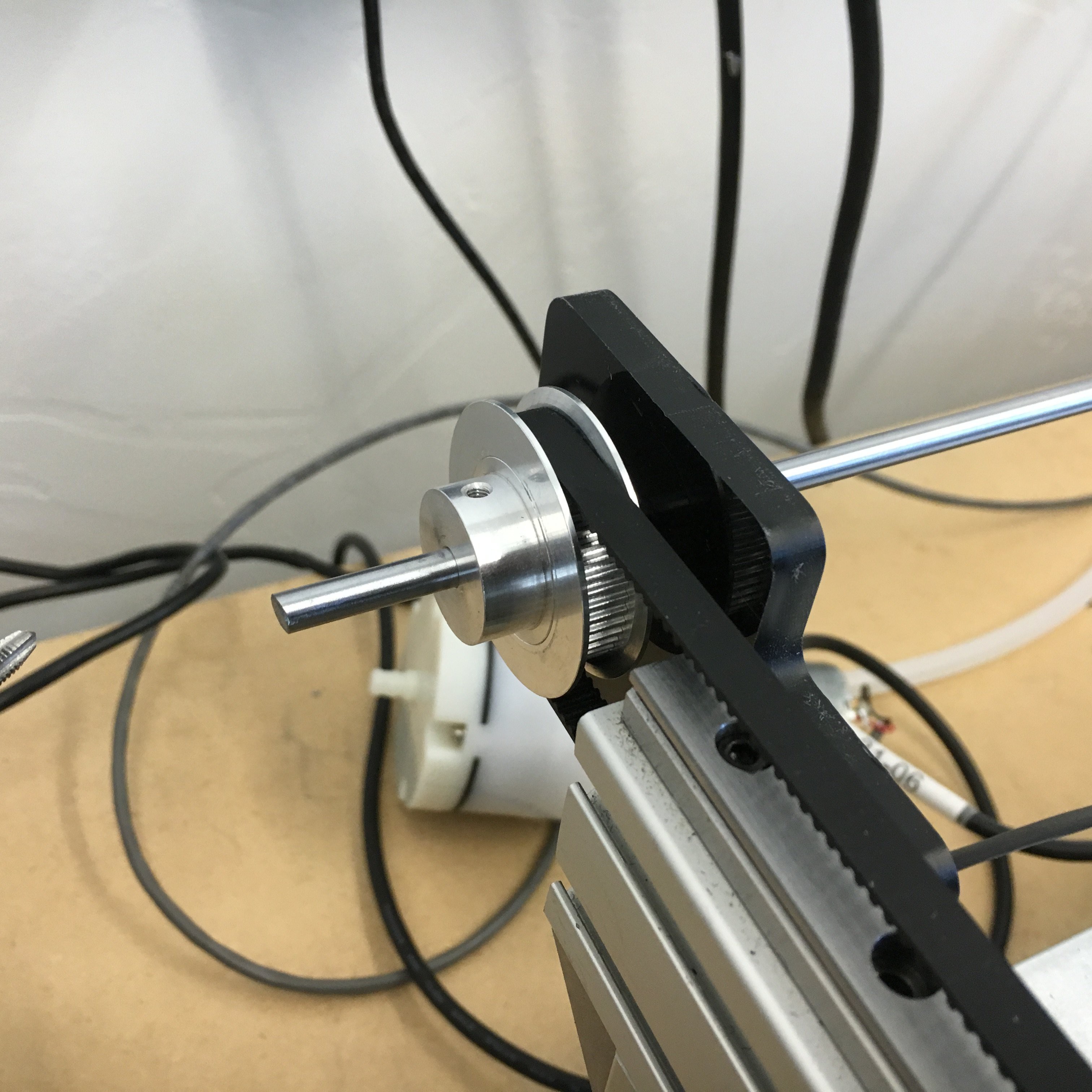
The mod consists of a rod which couples to the end of your Y motor. This rod passes through a modified end bracket with a press fitted bearing for support, and holds a toothed pulley that will drive the previously passive rail. NOTE: we were short a 5mm coupler so we used an old toothed pulley we had laying around until our actual coupler arrives.
-
Magnetic parts holder
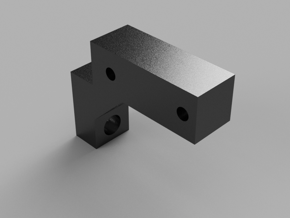
01/27/2016 at 00:39 • 2 commentsI designed a parametric model in Fusion360 for magnetically holding parts to the bed of our PNP. It has been built to allow you to specify how many lanes of parts you want, how wide the tape is, etc. From there it builds the body of your part which you can then either print or mill. For those of you who need something like this, or would just like to play around with the part, link is here http://a360.co/23rUlmW and the covers are here http://a360.co/1UriLHc
-
Endstops, Plumbing, and Electrical
01/26/2016 at 03:06 • 3 commentsWe've been running with no way to home the machine which has been something we have been putting off until today.
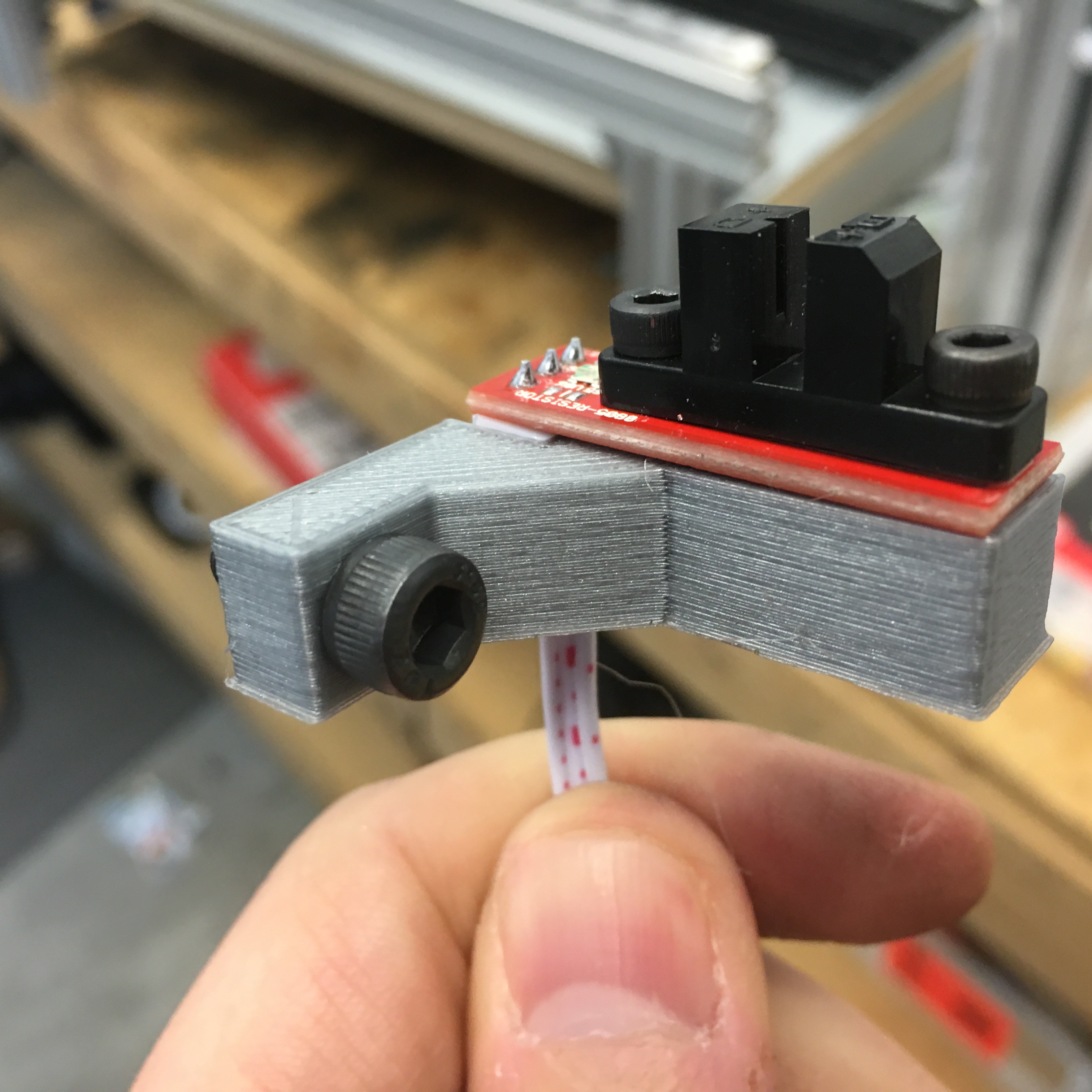
Its no secret that a lot of these projects, 3D printing, laser cutting, CNC, etc all share very similar components. The good news is that as result these components have dropped in price dramatically. When we went looking for endstops I wanted to stay away from mechanical stops and go with optical endstops. A very popular form factor in the RepRap world are the ones here: http://www.ebay.com/itm/321760461548
Of course they were not set up to bolt right on to the aluminum extrusion, but that isnt anything a little printer time wont solve. Here is what we ended up with:
![]()
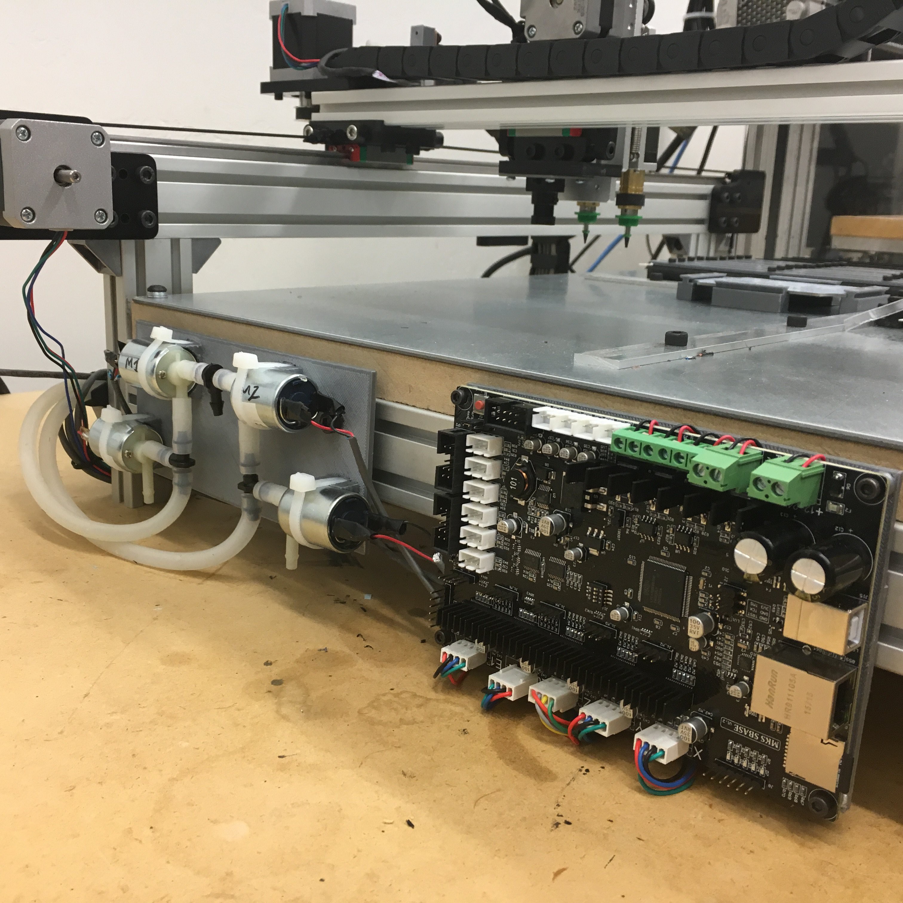
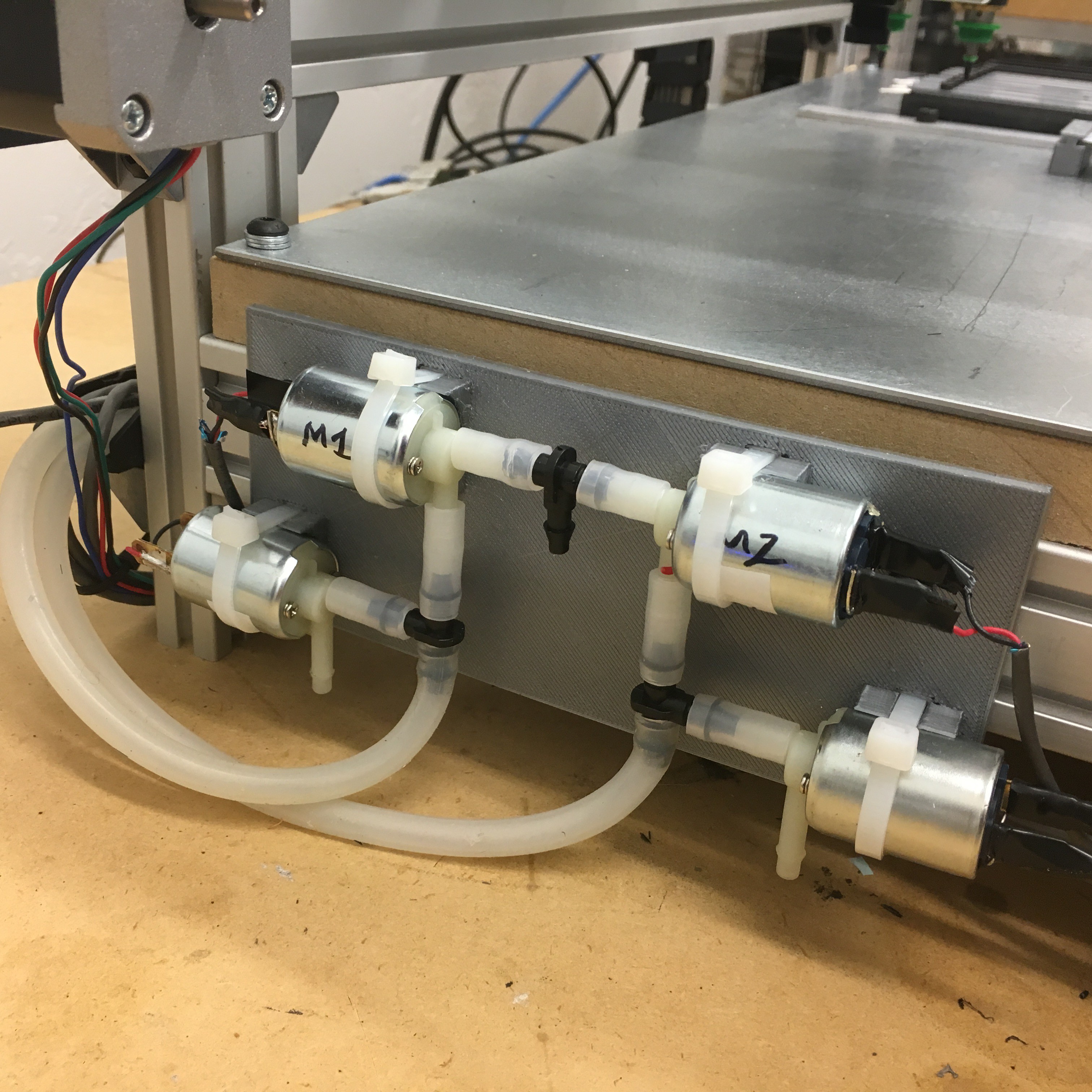
With endstops out of the way we turned to making sure the plumbing and electrical got all cleaned up. Its not an official enclosure, but definitely makes it easier to cope with. Long term we will do up a proper enclosure which will be really nice, but for now this is clean and tidy. Here a look at the rear of the machine. -
Camera Setup
01/25/2016 at 06:28 • 0 commentsI've been asked to share some of the details about how the camera is placed and set up. I am using the 6mm lens that came with my device. I dont have an 8mm lens to compare to. It does appear in the camera info that the resolution is 640x480. The lens of my camera is exactly 28mm from the surface of my PCB. The calibration wizard in openpnp calculated values of .23 for both x and y. Distortion does not appear to be a problem.
I'm unclear on the amount of settle time that is ideal for these ELP cameras as compared to other models, I think we are using 250ms now. What I am shocked at is how well the image looks in simple ambient lighting, the ELP is more of a "microscope" than my USB microscope ever was.
-
A new camera
01/25/2016 at 06:25 • 0 commentsAs I mentioned yesterday, we were enable to extend the USB on our microscope camera we had been using for downward vision. This ended up being a huge benefit for us because after looking at the images from the ELP camera (same used in Jasons reference machine) we were blown away at how bad the USB microscope was in comparison to the ELP. So, we went to work designing a bracket to mount the ELP, We recessed in the PCB so it would nice and flat, turned out great.
The camera I bought is this one:
http://www.ebay.com/itm/221448995232?_trksid=p2057872.m2749.l2649&ssPageName=STRK%3AMEBIDX%3AIT
They have them all over ebay and amazon. I've seen the 5MP versions as well, mine is only 1MP but I almost think the lower resolution will mean easier/quicker image processing? The picture is beautiful, even with only average lighting conditions.
The image quality and focus of the endoscope/microscope is not even comparable to the ELP. In addition, the endoscope/microscope did not have the same low light characteristics. Finally we were not able to extend the microscope USB cable enough to route through our cable chain. I had originally planned on only using the ELP on the upward looking camera, but now I may use it on both. I still need to run some PNP jobs with the new camera, but it looks pretty good so far.
![]()
![]()
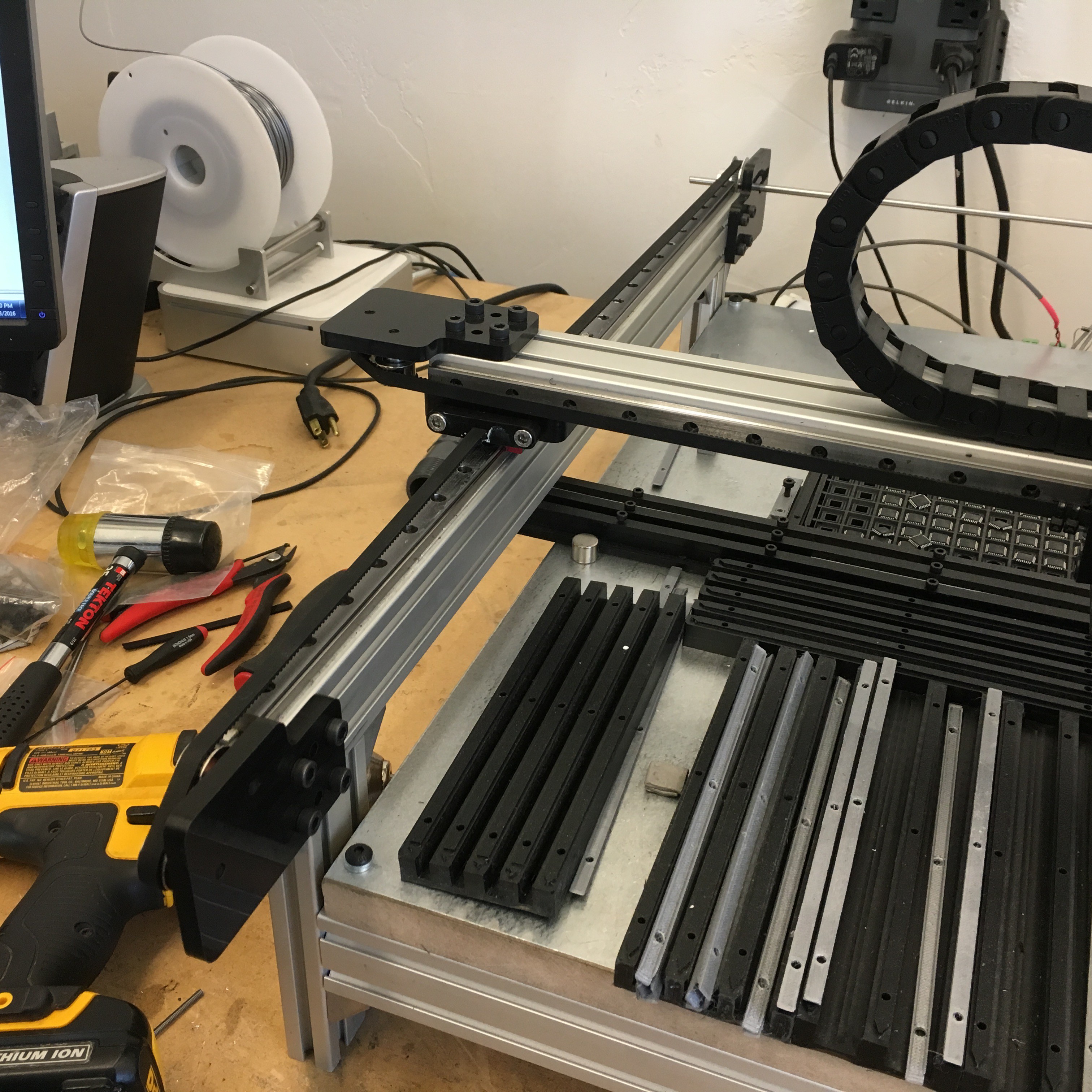
With the new camera in place we were able to return to getting the cable chain wrapped up.
We're now getting a mount together for all the plumbing and we can return to more testing in a more final type configuration. Wishing there were more hours in the day.
-
Wiring up the machine
01/25/2016 at 06:21 • 0 commentsSpent the day rewiring all the electric in cable chain and generally tying up loose ends. Of course there were some hiccups. First, the USB microscope we were using would not work once we extended the USB cable. This was odd because I think we were overall only like 8-10 feet which should be within spec. I had one of the ELP cameras laying around, and was able to extend the cable on that just fine, so I am thinking we're going to make a new bracket to accommodate that camera instead, the quality of the ELP was strikingly better in every way, it's probably just a superior solution. Designing the mount and will install tomorrow, I'll add a pic once it is done. Milled part holders for both 12mm and 16mm strips. Other than that things will look really nice with all the wires tucked away in the chain.
-
Picking and placing
01/25/2016 at 06:20 • 0 commentsIts starting to feel more and more like we will be able to pick and place board flawlessly. There's very little that is lacking. We placed and entire board flawlessly a couple times now. Just a few little things to iron out, mostly just learning how things work. Here is a shot of us placing parts in a pretty deliberate and steady manner:
-
Unlocking your nozzle stepper
01/25/2016 at 06:19 • 0 commentsWe ran into an issue where our NEMA8 steppers for the nozzle tips were not powerful enough to twist the rubber tube attached to it, even with the 180degree limit enabled. Looks like a couple people have gone with NEMA11 and special (expensive) adapters. We opted to print a little boot for the top of the motor that leaves the shaft to freely rotate inside. Problem solved!
The part is up on thingiverse here http://www.thingiverse.com/thing:1280038
3D files can be downoaded here http://a360.co/23dJGMF
![]()
-
Why rails and slides for our PNP?
01/25/2016 at 06:16 • 0 commentsMany people who are looking at this project may notice some similarity between it an the reference design Jason from the openpnp.org project posted. His design (and great software project) gave me the confidence to know that building a cartesian design could work.
The designs Jason and I have posted are very similar. Let me explain the main difference and why I went the way I did. The main difference is his design uses wheels that ride in a slot on the extrusion, and mine use steel rail and slides. The reasons I chose rail/slide as opposed to openbuilds:
1. I had experience with other x/y platforms like the shapeoko and quickly grew tired of tinkering with the eccentric nuts dialing in the tension. Too tight and it wouldnt move (or skip steps), too loose and there was slop. And even worse (perhaps because it was CNC) it changed every time you used it so you had to go over the machine regularly tinkering to keep things operational. I have heard from several people that this wasnt their experience, but as I evaluated my options, and give my experience, I knew that if I designed around wheels on extrusion, and it didnt give me the accuracy or precision I needed for small pitch PNP parts, then I would have effectively painted myself into a corner.
2. The rail/slide option gave me a variety of options in quality/cost which would be easily swapped if an option was not able to deliver the speed/accuracy/precision I was after. Had the cheap chinese rails works (they didn't) they would have been a more cost effective solution than the openbuilds option.
3. Slide/Rail were already proven to deliver great speed/accuracy/precision over a long lifespan with minimal maintenance, I wasnt sure the openbuilds solution could deliver that.
4. I wanted to have a passive rail and avoid the complication/expense of having a second stepper to drive the Y axis. Only rail/slide could deliver the kind of butter smooth motion that I would need to do that.
5. I love clearpath closed loop servos, and wanted to leave the door open to jump from cheap steppers over to the more capable servos which come in a nema23, the openbuilds brackets dont come in a nema23, so building my own gave me that flexibility.
It obvious that either route will give you the ability to pick and place parts. I would bet that the openbuilds route may come in a little cheaper, but I think long term we will be able to eek out more performance, with lower maintenance, from a rail/slide based solution.
-
First Blood!
01/25/2016 at 06:11 • 0 commentsFirst pick and place in the books! Note that in our dry run, we enabled both nozzles and it was a lot faster to grab and place both parts in a single pass, but for this video Jason disabled the 2nd nozzle because we have a HIWIN rail/slide on the head that keeps sticking. Not sure if we should get a more powerful spring or what. Robotdigg was kind enough to send us a new rail/slide to replace it with, but it is just a rough as the one it replaces.
Here is the successful pick/place:
Here is a dry run with 2 nozzles enabled:
DIY Pick and Place
Cartesian PNP machine using Rails/Carriages for high speed and accurate part placement. Affordable open source pick and place is on the way.
 anthony.webb