 Yann Guidon / YGDES
Never settle, kids !
Electronics is an experimental science, that's why I love it :-) As long as you have not tried everything, you can't be sure ! Yesterday I had not explored the whole design space and something was missing. Well, I couldn't leave all the stones unturned so I came back to this today.
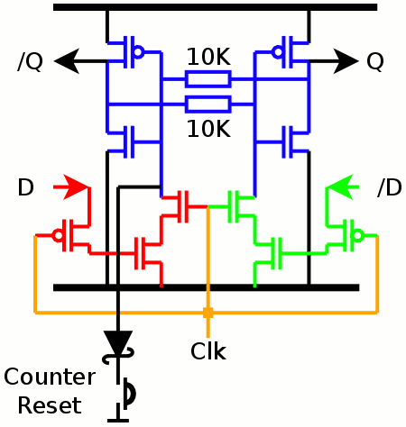
I moved the clock enable transistors between the latch and the data-clear transistors to see if this changed something. Well, I feared the worst due to capacitive coupling(s) but actually it turned out better.
That's the traces with the new topology : top trace is the Q signal (latch output) and the lower trace is the latch's gate. It's cleaner and I can better see the RC curve.
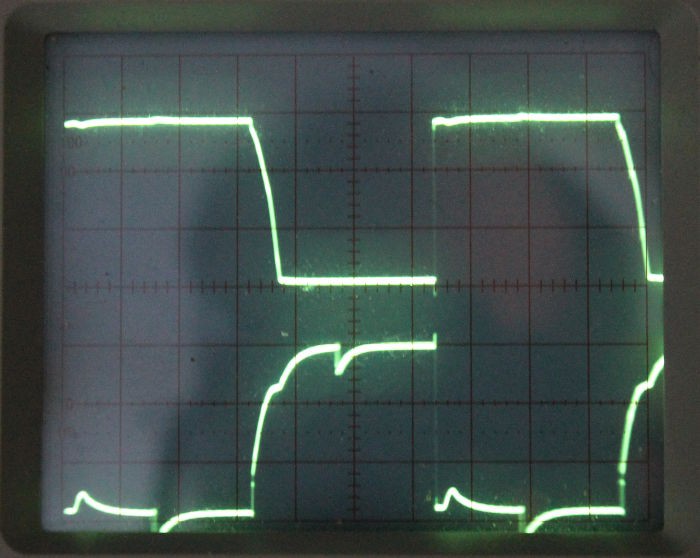
The difference is enormous and the capacitive coupling is not as catastrophic as before.
But wait, there was still the couple of Ge diodes (1N60). What if I remove them ?
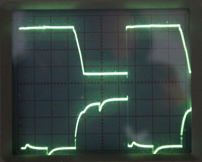
Howdy ! They are almost identical ! There is just a slightly different slope here or there.
I saved 2 parts and it's still as fast !
It seems that the resistor value is really important too and 10K is "right" for 30KHz. No wonder that it failed at 30K Ohms, the FETs are fully latched in the middle of one level so at 30K Ohms, the value is not settled (almost but not by much).
It allows me to deduce a handy rule of thumb : if 10K Ohms is ok for 32KHz, then 20K is ok for 16KHz, 40K-> 8KHz, 80K -> 4KHz etc...
It's funny because I finally come back to the original design but I got the resistor values wrong, thinking they were not significant. At 32KHz, they are, but at low frequency (a few Hz) 100K Ohms or 1M Ohm is ok. I'll have to find a compromise but it allows a wide range of options that lead to even more economies.
:-)
Lesson learned :
the resistors are OK for small, slow circuits. Fast circuits need to be devoid of resistors because the RC cells are too much a hassle. If I want to make a faster design, I'll be forced to use a 12T FF.
Discussions
Become a Hackaday.io Member
Create an account to leave a comment. Already have an account? Log In.
What's the MOSFET bodycount so far, Yann? :)
Are you sure? yes | no
I've only broken 2 or 3 lately :-)
Are you sure? yes | no
You should be able to use much lower value resistors as the current across the resistor that is pull down over a very brief moment while the F/F changes states. It is probably less than the amount of gate currents in your MOSFETs. Averaging that over time, it will be small.
Are you sure? yes | no
Yup, it's a compromise to find. Keep in mind though that I will have 38 such cells in parallel so the total current must be multiplied by as much.
If the resistor value is too high, changing the state will take forever and the cross-conduction current will flow through the N and P drains "for a while" (I chose 3V because the cross-conduction current is low).
If the resistor value is too low, well, it will switch very fast and will make spikes in the power supply.
With 10K, I can already calculate that the spike current will be around 12mA if all the 38 cells are toggled at once (for about 15us). I must add the power drawn from the display (a few mA) and I can evaluate the average current to be around 5 to 10mA, with quite a few spikes...
Fortunately the 2^15 divider is a ripple-type so the spikes are spread over time. But still, at midnight, it's going to be interesting :-D
Are you sure? yes | no
The amount of cross conduction current at your CMOS output stage during the slow transition is probably more significant than this. Both of the P & N MOSFET will be on until the output settles on high or low. You are far better off to stiwch them as fast as you can to save current.
Use decoupling caps to solve these type of current spikes.
Are you sure? yes | no
I have measured the cross-conduction current at https://hackaday.io/project/9376-yet-another-discrete-clock/log/32133-power-supply-voltage and it's an order of magniture lower that the 10K resistor's current at 3V.
I'll measure again with the BS170-BS250 pair : short-circuit the drains and gates, power with 2×AA batteries (about 3V) and measure the current... Of course this varies with temperature and whatnot.
The 10K resistor will draw about 300µA @3V, cross-conduction was about 20µA max. I'm in favor of a "soft switching" in this case. I'll tell you after I have measured again :-)
Are you sure? yes | no
OK, I short-circuited the gates and drains of the BS250 and BS170 and could barely measure 1.1µA. Let's compare this to the 300µA of the 10K resistor.
If the CCC (Cross-Conduction Current, sorry, I'm lazy) is so insignificant, it doesn't matter if the resistor is higher or lower. The flipping energy (current×time) is the same. However, a "softer" switch will reduce the EMI and the decoupling (there will be some, of course, but I need to evaluate it).
So here, the resistor value is determined by the RC constant that lets the latch flip. 10K is just enough to allow safe operation at 32KHz. A 5 to 10µs edge is ok.
Are you sure? yes | no
OK you got me curious : I'm going to measure the circuit's consumption...
Are you sure? yes | no
Quiescent current of the 10TFF : unmeasureably low.
Damn, I have to be extra cautious about the voltmeters' internal impedances (I use several to double-check simultaneously), and I erroneously measured one voltmeter's current draw (0.3µA@3V, that's 10MOhms).
When switching at 32KHz, I measure about 70µA. Thus, the whole predivider would draw about 150µA in average... I'm not making a wristwatch so it's "good", I wanted to make a power-saving system that could be powered by a couple of AA batteries but the display LEDs will draw much more so it's not necessary to search further.
Are you sure? yes | no
The circuit works correctly down to 1.9V so 2V is safe.
However something strange happens at 3.3V, the oscillation breaks down, I can't understand why yet.
Are you sure? yes | no
I wonder why the whole circuit draws around 70µA while the ripple current is very low (might be around 5%, observed across 1K Ohms in series with 5V, decoupling is with 10nF). When the clock input is suppressed, the current disappears.
During the transitions, I see a short burst but it's too short (around 200 or 300ns, including ringing) to be caused by the 10TFF. I suspect it's an artefact of the very clean output of the DS32KHz.
Since the idle current is zero and there is no load on the Q and /Q nodes, the only explanation is the charging/discharging of the gate capacitances. This can only be checked with a variable frequency source......
Are you sure? yes | no
15µA@1KHz (though not 3Vpp). It's higher than expected but that seems to confirm my guess of a frequency-dependent current draw (though I expected something like 65µA*1KHz/32KHz = 2 or 3µA)
Are you sure? yes | no