Dan Royer
-
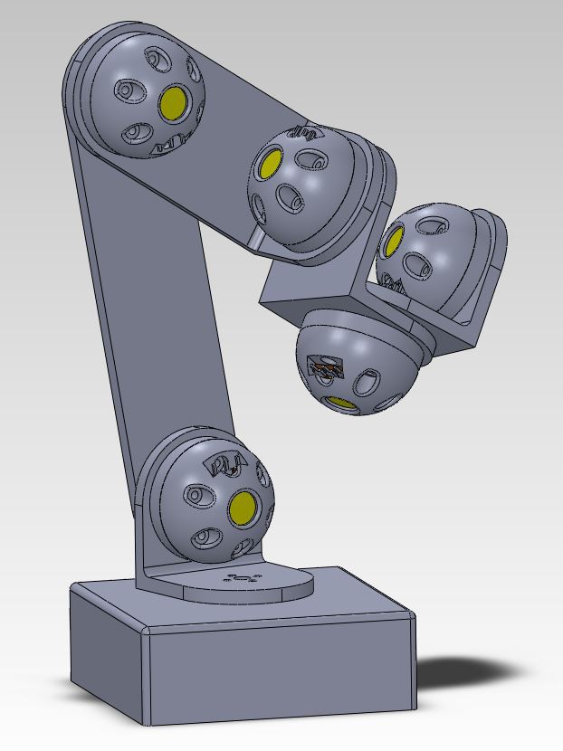
UBC student prototype
04/10/2015 at 18:48 • 0 comments![]()
This picture shows my first metal arm (three years old?, center left), two of my wood robot arms (from a year ago), and the prototype UBC student engineers just delivered. It runs a beaglebone black and has two identical sections. The idea is that three sections put together would make a 6DOF arm.
The bad
The third section would have required very expensive Dynamixel motors that were out of budget for this prototype.
The servos are normally 270 degrees, then geared down for power, leaving a range on each joint round about 30 degrees. Not enough to satisfy!
If I were to mass produce this 3D printing would be a total no-no. Cable routing is a mess.
The good
I really like the modular design because I'm always thinking about how to make 1000s more. The math says this arm would be long enough and lift enough weight for my specs. It is surprisingly stiff! I wouldn't have expected the 3D printing to take those kinds of forces. Speaking of which, the 3D printing is gorgeous at 60% infill.
Next
I've been working in parallel on a plan B, so we'll see how that goes and compare the two on the far side.
Also posted on http://www.reddit.com/r/robotics/comments/325bsh/i_asked_ubc_students_to_build_a_robot_arm_for_me/
-
Gearbox 3 Attempt 2
03/31/2015 at 22:12 • 0 commentsDown to the wire! A year ago I said at the Bay Area maker faire I would have my new arm at next year's event. Now here I am waiting for the design of the second version and I'm really feeling the pressure. I want to deliver so badly!
In the meantime I've been working on the software. I have enough robots now that I can see how their programs overlap. I'm bringing them all together into a single framework so that they can work together and share a common core.
It occurs to me that I've made three different hypocycloidal boxes and this is my second attempt at the latest. That means I've learned... six ways to not make a gearbox.
-
Gearbox failure?
02/25/2015 at 00:00 • 11 commentsSo I built the pillow block described in the last post. First I 3D printed one in about 2.5h and when I went to install the gearbox I snapped the block in half along the layers (what's commonly known as 'delaminating').
Then I designed and laser cut a replacement in about 20 minutes. So there. Ask your local make if 3D printing is right for you.
The new block was assembled and a 45cm bar was attached to the shaft. Now at 55:1 reduction on a 50 N·cm stepper motor should give me 2750 N·cm, or a holding torque of ~61.1Nm at 45cm. That's a LOT of torque for such a small motor.
The new block assembled, the gearbox stalls even with my hand on the bar at the 10cm mark. This thing should be almost unstoppable.
I don't have enough engineering experience to solve the mystery and I'm led to believe neither the machinist who made the parts nor the designer who drafted them can spot what's wrong. I've got some expensive ideas, but I'd really like to get a Mechanical Engineer to take a look and tell me what's going on.
So... two steps forward, one step back. Next step is to find the Mechanical Engineer who can help.
-
Gearbox prototype made
02/12/2015 at 14:56 • 0 comments...aaaand that's about all I can tell you for now. It's made, it's assembled, and it's running on my desk. There's no discernible backlash - as promised!
at 55:1 reduction on my 200 step per turn motor at 1/16th microstepping we're looking at 176,000 steps per rotation, or 0.002 degrees per step. It ain't fast, and it don't need to be.
The first prototype cost $1050 CAD. The next five I'm told will cost ~$200 each. Once I get that far and have a demo arm, there will probably be a kickstarter for the gearbox.
The challenge now is testing this thing to see how much torque it can handle. I need to make a pillow block to hold both ends of the output shaft so that all the force on the motor is just rotating torque force, then attach a bar and start hanging weights off the end until it can't move any more. Repeat for different speeds.
I'm planning a single joint with two rotations. Three joints is 6DOF. Length can be increased by adding space between the joints.
-
Machining costs...wow!
01/21/2015 at 16:46 • 1 commentThanks, Hackaday.io for the feature.
Today I received the first quote from a machinist for the gearbox prototype. In order to get my power and precision I need a gearbox that doesn't exist. Jim Shook, a fellow Hackspace member, designed a box as per my specs four custom parts and a bunch of McMaster Carr pieces. Each of the four pieces averages $250 to make one!
I guess I don't know what I expected. The same company made parts for my first robot. It was a crab that walked and the parts cost over $600.
So I'm putting it out to you, Internet: where do you go for machining? I have igs/step files and PDFs of the tolerances and materials.
-
Modbot stealing the thunder
01/16/2015 at 20:52 • 0 commentsThank you all for your continued support, follows, and likes.
In the last few months I've found some students from the University of British Columbia MechEng program who have taken my ideas and are running with them. Together we're building a prototype 6DOF arm that I hope will be ready in a few weeks.
Meanwhile, I see that other people like my ideas and are running with it. Check this out:
That would be me if I could go faster! Should I have worked in secret and filed patents? I don't have the experience to know how I could have done it better, and that I don't know how to get that experience makes me bad-crazy. I really need help.
-
New video added
08/19/2014 at 23:44 • 1 comment1 minutes, 59 seconds! The trick with filming on a potato is to find one with good eyes so you get a clear picture. As you can see here, my spud is a little stale.
-
System Diagram added. All requirements met?
08/18/2014 at 19:59 • 1 commentCan you please tell me if I'm missing a req for stage two? Please 2x check my work so far.
I'm really frustrated by the lack of progress in a several areas. I get stuck in one place, I try another, I get stuck there, I try another, then I have lots of mostly finished things all demanding my time. I may have to throw money at the problem and figure out how to pay for it later. Time to call some machinists.
-
There's more than one way to skin a cat ||
07/21/2014 at 01:31 • 1 commentTeaching a robot arm what to do from a keyboard with inverse kinematics is friggin' hard. The IK has lots of singularities - special cases where things suddenly go stupid. To avoid this I'm trying to make a 6DOF joystick.
![]()
It works just like the robot arm but it has no motors. When I move it around the arduino in the base will pick up the angle values, copy that to the simulation on the screen, and even send it to the robot arm.
I've already made the sensor blocks. See picture 1 and picture 2 on instagram. There's a sensor block under the base, next to the arduino. I need some 5mm female headers to plug in and someone to help me make the base, the L brackets, and the other mechanical parts. Anyone want collaborate with me?
In the mean time I'm printing another 5 blocks.
I hope this joystick will have other uses, too. Maybe Kerbal Space Program fans will be able to pull of orbital maneuvers more easily.
-
There's more than one way to skin a cat
07/13/2014 at 03:32 • 0 comments....aaaand now the internet it horrified of me. Ah well, I guess I'll just have to be a super villain.
The meaning of the expression is that there's more than one way to solve a problem. I've been very stuck on the softare because I've been trying to drive the robot using a mouse and keyboard. I've come up with a new idea that should work better: I can use 6 potentiometers, an UNO, my 3D printer, and some metal bearing balls to make a scale model of a robot arm that connects with USB to the computer. The computer would copy the real model's movements to a computer model that could be recorded and played back. Best of all, I've done all these kinds of things before. There's no mystery parts to figure out!
Now I feel like I know what to bring to the New York Maker Faire. Will I see you there?
5+ Axis Robot Arm
Building an open source robot arm for makers and small businesses