davedarko
-
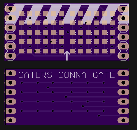
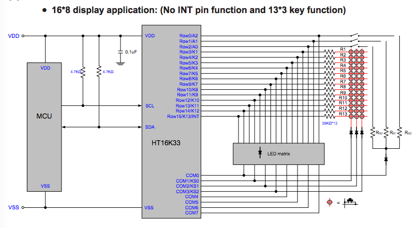
HT16K33 to help with my ancient ancient displays
10/13/2016 at 09:34 • 4 commentsSo at first I was about to edge a board and use some L2803s and 595s Shift registers, but then I saw that the HT16K33 matrix controllers are now so cheap that I bought 5 for 6,50 Euros. Lucky me, I've mistakenly marked the cathodes with red pins - but the math checks out. I have 3x5 positive pins and and 3x6 negative pins, so that makes 15 rows and 6 common columns - yay. https://cdn-shop.adafruit.com/datasheets/ht16K33v110.pdf 0x01 notes for the future - can anyone have too many displays?
0x02 NTTF - Stargate LED matrices0x02 NTTF - Stargate LED matrices [UPDATE]![]()
![]()
-
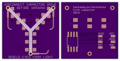
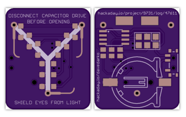
The flux compensator
10/13/2016 at 04:35 • 5 commentsPlease. I know. It's flux capacitor. But that might happen to every german-syncronized-movie-watching person. Maybe it's because of the drawing that says "flux compression". I still want to know what happened there.
Parts are all 1206 and super easy to solder.
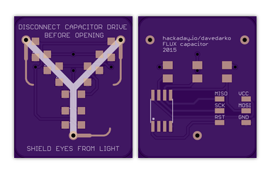
Version 1
![]()
Version 1 - Rev 1
![]()
Version 1 - Rev 2 - final
I've updated the design to also have a battery holder and a switch (yay), also soldering points for a clip. Checkout #FLUX capacitor trinket for future updates :) ALSO: there's a four led, more resistors version by @Bastiaan - #Mini flux capacitor prop PCB
![]()
![Order from OSH Park]()
int outer = 0; int center = 1; int inner = 2; int pwmValue = 22; int timeLength = 250; int delayValue = 10; void setup() { // put your setup code here, to run once: pinMode(outer, OUTPUT); pinMode(center, OUTPUT); pinMode(inner, OUTPUT); } void loop() { // put your main code here, to run repeatedly: softPWM (outer); softPWM (center); softPWM (inner); delay(timeLength); } void softPWM (int pin) { for (int j=0; j<timeLength/delayValue; j++) { for (int i=0; i<pwmValue; i++) { digitalWrite(pin, HIGH); delayMicroseconds(delayValue); } for (int i=pwmValue; i<=255; i++) { digitalWrite(pin, LOW); delayMicroseconds(delayValue); } } } -
props
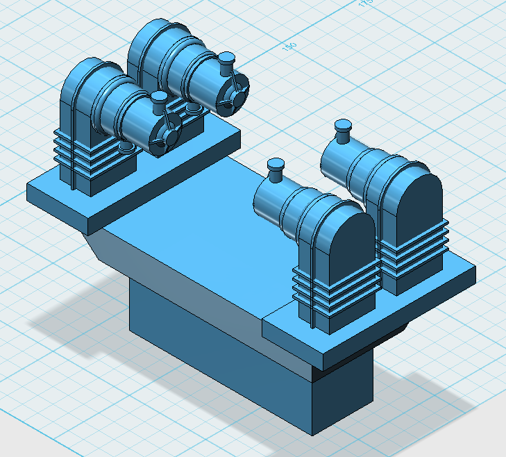
02/18/2016 at 09:41 • 5 commentsAlthough this is meant to be a board in general, I also have this 3D file that I could totally scale to fit some EL wire or 3mm LEDs. It doesn't seem to be too accurate though.
![]()
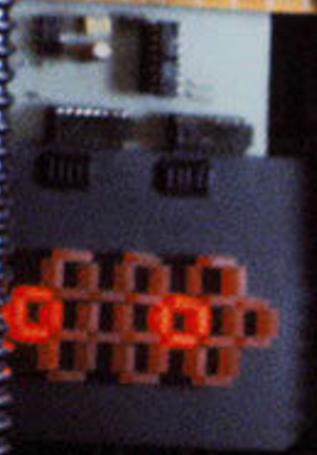
but initially this board was intended to be used on the blinking prop seen on 'Empire strikes back'. It's pretty easy to see the 555 with its caps, a 4017 to its right and the two ULN2004s with the 10 resistors for the 10 x 4 LEDs.
![]()
The 4 stages:
/*

 O # O
# # # #
 # O #

 # # #
# O # O
 # # #

 # O #
# # # #
 O # O

 # # #
O # O #
 # # #

 */
blinking things
this is a rebranded project, sorry guys. take your skulls/likes back if you want :)