Close
0%
0%

"Solar Pi Platter"

A Li-Ion charger for Solar or USB with PMIC/RTC, 5V boost converter and USB Hub that can run Linux for only $5 more!

Similar projects worth following
The Solar Pi Platter is a battery-power expansion board for the Raspberry Pi Zero. It is designed to be flexible enough for a lot of applications from solar-powered remote sensing to built-in UPS functionality for small file servers. Although yet to be proven, the idea is for the board to sit under the Zero and connect using 4 pogo-pins to the test pads. This preserves the 40-pin expansion header for traditional Pi HATs. I also included 4 pads to allow connection to a USB cable on this rev of the board in case the pogo-pin idea problematic. While I designed this board for my own ideas and for some projects that other members of my local makerspace are interested in, I decided to enter it into the HAD/Adafruit Pi-Zero contest to see if other people might be interested in it. It's a little bit of a funny project because it will cost a lot more than the Pi (especially in low volumes). That's why I jokingly refer to it as an expansion board that can run linux for $5 more.

Component selection

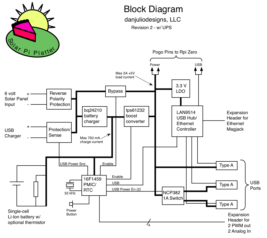
  • TI bq24210 Li-Ion charger supporting both high- and low-impedance power sources. Configured for a max 750 mA charge current to external battery. Support for an optional external thermistor (103AT-4 type) attached to the battery.
  • PIC16F1459 PMIC/RTC. Inexpensive micro-controller that supports a USB interface so the board can appear like a CDC-class serial port to the Pi. External 32 kHz crystal to support a very simple RTC (seconds since some point) and alarm-clock functionality to be able to wake the board up at a specific time. External power button to manually turn the board on (and off). Charge status, low-battery detection (and shut-down after warning), USB power fault detection. Two analog input pins and 2 PWM output pins for simple IO functions without requiring further connection to the Pi. The analog inputs can be referenced to an internal voltage reference or the PIC VDD. I hope the PWM outputs will be support both servo-motor control as well as traditional PWM output.
  • TI tps61232 boost converter. Supplies up to 2 A @ 5volts for use by the rest of the system (USB/ethernet, Pi, Pi HAT and any attached USB devices). Note that you'll require beefy enough wiring from the battery to support this at full power output since you will be drawing 3+ A from the battery at lower battery voltages.
  • LAN9514 USB Hub/Ethernet controller. Not-so inexpensive controller that I picked because I figured it was compatible with the Pi and supported both USB and ethernet. I'm assuming it can run without an external EEPROM but I brought the signals out just in case.
  • NCP382 USB power switches. Each USB connector has a separate power control allowing code running on the Pi to turn-on and off USB devices to save power. One connector has both outputs of the NCP382 ganged together for a nominal maximum output current of 2A. The other connectors are each connected to one NCP382 output for a max of 1 A current (this is the rated max of the NCP382 before it current limits - I imagine useful maximum current is somewhat lower).

Connectors

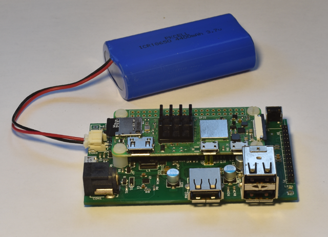
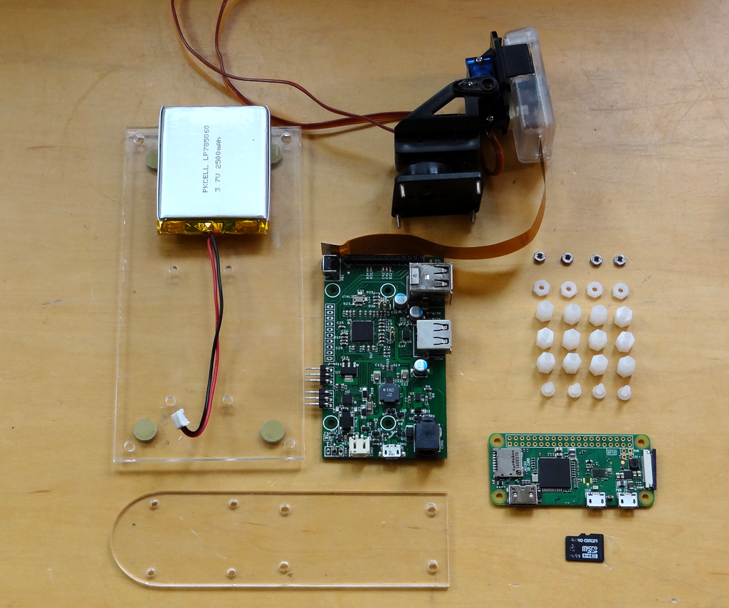
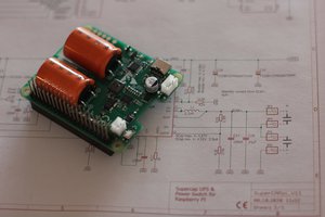
  • 4 Mill-Max pogo-pins making contact with the Pi PP1, PP6, PP22 and PP23 test points for power and data to the Pi. The board is connected to the Pi using 0.25" nylon stand-offs.
  • 3-pin 0.1" spaced header and 2-pin JST connector with reverse polarity protection for a single cell Li-Ion battery (for example 2000 mA devices sold by Adafruit and Sparkfun or 18650 type). A solder jumper (J1) that is removed when an external thermistor is used.
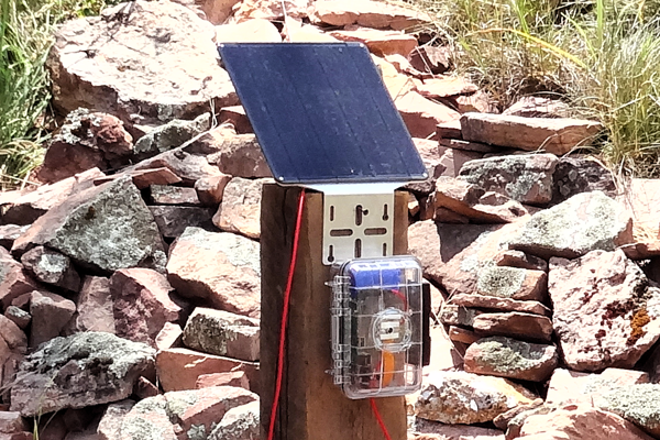
  • 5.5x2.1 mm barrel connector 6-volt Solar Panel input with reverse polarity protection designed for typical 6-9 watt panels that can be found online (7-volt max open circuit voltage)
  • Micro-B USB connector for 500-1000mA USB charger
  • 3 Type-A USB connectors for USB expansion. The high-current USB connector is spaced 25 mm from the next USB connector to allow "fat" USB devices like cellular modems.
  • 13-pin 0.1" spaced header (along the "top" of the board) for an MagJack ethernet connector break-out board (like the Sparkfun BOB-13021). Two solder jumpers (J3, J4) that can be added to allow the LEDs on the MagJack to operate (at the expense of slightly more power consumption).
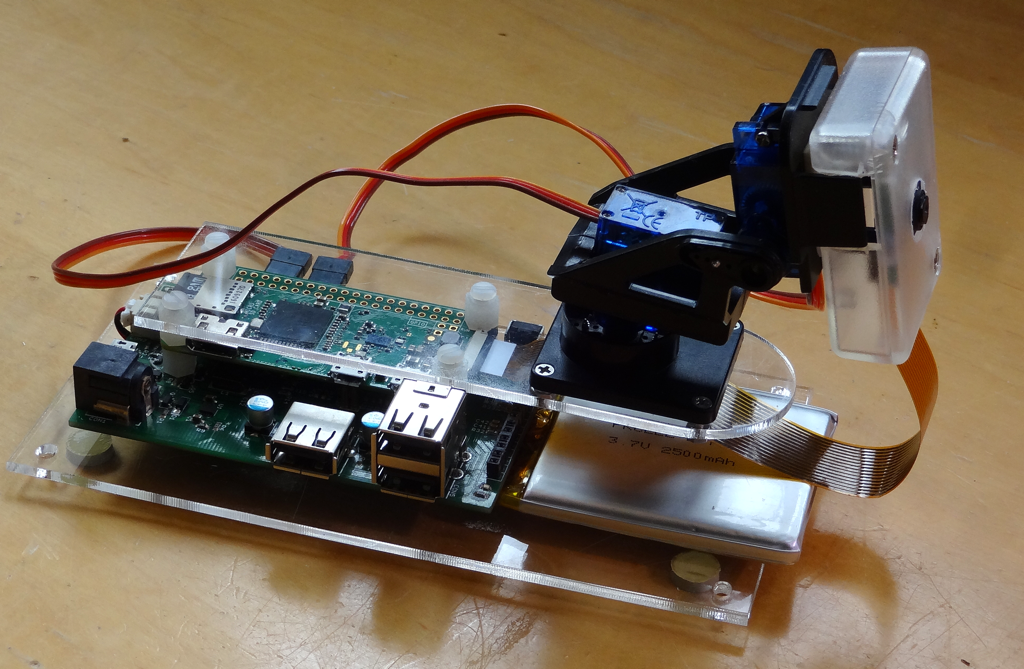
  • 16-pin 0.1" spaced header (located under the Pi's expansion header) for user-signals including the analog inputs, PWM outputs and various voltages used on the board. I imagine using right-angle headers to get access. The PWM outputs are slightly separated to allow easy connection of 3-wire servo-motors (data, +5, ground).

PIC Firmware

  • Currently I am hoping to implement the following functionality on the PIC. It may be tricky because I want to see if it's possible using the free compiler.
  • Simple ASCII character command set sent/received through a CDC-class serial port. Along the idea of "A0<CR>" to get the analog voltage on analog input 0 or "P1=120<CR>" to set a PWM value. Other commands to control the board power, USB port power, set/read the RTC and alarm, set/read EEPROM values.
  • Simple RTC that is essentially a second...
Read more »

solar_pi_platter.pdf

User Manual

Adobe Portable Document Format - 9.14 MB - 01/03/2017 at 21:03

Preview
Download

solar_pi_platter_schem.pdf

Schematic for the Rev 03 board that went to production for the kickstarter boards.

Adobe Portable Document Format - 200.17 kB - 11/05/2016 at 16:19

Preview
Download

  • A portable computer using the Pi Zero 2 W

    Dan Julio08/28/2022 at 19:02 0 comments

    I recently needed to test some software I had written on a Raspberry Pi.  I have a Pi 4 with the official 7" LCD but it turns out that screen doesn't have enough vertical resolution so I hit Amazon looking for better screens.  One thing led to another and I soon was working on a new project as an excuse to play with the Pi Zero 2 W. 

    The Norsmic 7" 1024x600 pixel monitor sports higher resolution as well as capacitive touch and two amplified speakers for audio.  The Pi Platter along with a simple custom 3D printed mounting plate was the perfect power manager for a portable computer.

    If anyone is interested, the full build details on are github.

  • Works with Pi Zero W 2!

    Dan Julio12/17/2021 at 16:41 0 comments

    The Pi Foundation must have noticed that this and other boards were using the test pads on the bottom of the Pi Zero for expansion products.  The Pi Platter works with the new Pi Zero 2 W!  Makes a perfect expansion/battery-backup board with a 5.1V 1A charger and 4.4 Ah battery.

  • Extending Motioneyeos with servos and on-screen display

    Dan Julio10/21/2019 at 21:59 0 comments

    This is a project I've wanted to do for a long time and finally found some time.  Calin Crisan's motioneyeos is a complete Linux distribution that turns SBCs like the Raspberry Pi Zero into complete web cams.  *AND* it's extensible. 

     The Pi Platter's USB UPS functionality is perfect for making a webcam that has built-in battery backup.  Pan/Tilt servos and an on-screen power status display can easily be added by including the talkpp utility program and five simple bash scripts in a motioneyeos system.

    Complete instructions can be found on the github if anyone wants to make their own.

  • Solar powered time-lapse camera

    Dan Julio07/20/2017 at 03:12 0 comments

    Just a note about a fun project with the Pi Platter that might be of interest to others.  A simple script uses the features of the Pi Platter to make a stand-alone time-lapse camera.  The script runs from /etc/rc.local, gets the time from the Pi Platter's RTC, takes a picture and then sets a wakeup alarm for five minutes in the future and then shuts down the Pi and powers-down to conserve power.  A switch connected to one of the Pi Platter's analog inputs can be used to disable the time-lapse photography system and allow the Pi to boot to a command prompt for off-loading pictures.

    A complete write-up including OS configuration and the script can be found at my website.

    The script also collects battery and charging data and during the week I ran this in the Colorado summer, a 4400 mAh battery was kept completely charged, even on overcast and rainy days using a 9W 6v panel.


  • Kickstarter fulfilled

    Dan Julio01/03/2017 at 21:13 0 comments

    Despite a shipping mishap with the production test fixture PCB (sent to Brazil during a strike there), we were able to fulfill the kickstarter campaign on schedule with boards shipped to backers in December. Next up is to find a distribution channel to sell, at least, the remainder of our production run of boards. If there is ongoing interest then we can make another production run.

    I also added a set of software utilities (the talkpp utility to communicate with the board and the ppd daemon), example code and documentation to a github repository (in the project description).

    Production in progress...

  • Rev 2 PCB Alive

    Dan Julio09/20/2016 at 02:00 0 comments

    The second revision of the PCB is back and one unit built. Although there is still a bunch of testing to do it's alive. So far I have found a swapped set of transistor silkscreen part number labels.

    Here's the board with a Pi Zero 1.3 booted from the HDD.

    The new revision.

  • 2nd rev layout almost complete

    Dan Julio08/01/2016 at 19:17 0 comments

    The second revision of the Pi Platter PCB is almost done. Hopefully the only additions will be various test points, if necessary, for the manufacturing test fixture. The main changes were the addition of the USB UPS bypass functionality and changing to use a stacked USB connector so the area around the PI Zero's HDMI connector was free of interference. I also slightly improved heat sinking for various parts and tightened up the high-speed signal layout as well as making sure the ground plane was improved in a few areas.

    I am currently thinking the manufacturing test will be essentially a functional one, connecting to all IO ports (and any necessary other test points) and then under control of a computer we'll test the power subsystems and enumerate the USB bus and make sure we can communicate with all downstream devices. I don't think we will end up building huge volumes of this board so perhaps it's ok if the test is a little labor intensive (e.g. manually plugging in USB cables, etc.).

  • Rev 2 Hardware prototype wherein the Pi Platter gets UPS functionality

    Dan Julio07/08/2016 at 17:57 0 comments

    One of the configurations I tested during debugging of the original prototype of the board was a Western Digital hard drive connected to the board along with a WiFi dongle and keyboard/mouse powered by a USB charger. The average current consumption (even when the battery was fully charged and at its highest output voltage) was above the maximum 750 mA that the charging circuit could provide which meant that the battery was slowly discharged. So there was no way to use the Pi Platter as a battery backed file server (or other HDD-based application). I thought briefly about trying to find a different charger (750 mA is near the bq24210's upper limit). The problem is that to support our maximum load of 2 A it'd have to be at least a 2 A charger which would increase cost as well as possibly limit the battery selection since 2 A could be too much for smaller batteries. So I decided to add a bypass circuit that would power the system directly from the USB charger and from the battery through the boost converter for solar applications or when the USB power failed. This meant a couple of new control signals to the PMIC that was currently out of spare signals. One thing I had been contemplating already was making one of the USB ports "always powered" instead of switched to prevent a case where the user could make it not possible to access their Pi to make change. This freed up one signal. I decided to remove the Power Good status signal from the bq24210 for the other since it didn't seem all that helpful.

    The critical timing for the UPS functionality is switching from a failing USB Charger voltage to power from the Boost Converter without the +5V rail falling below 4.5 volts. There are 3 parts to the timing, a falling USB voltage to some threshold that indicates it's no longer good, the time for the micro-controller to detect and act on that signal and the time for the boost converter to start up. Switching from battery power to USB power isn't as critical because we can leave the boost converter running for a tiny bit while validating the USB voltage and switching the bypass back on. The USB Charger voltage is fed through a resistor divider into a comparator on the micro. The output of that is routed as the highest priority interrupt so the boost converter can be switched on by an ISR and then power-fail validation, state management, etc can be done in the main code. Voltage falling below around 4.7 volts to boost converter enable is less than a micro-second. It then takes a few milliseconds for the boost converter to start up which can be covered by bulk capacitance on the board.

    The bypass is comprised of two back-to-back P-channel MOSFETs to prevent current from flowing in the wrong direction depending on the various use cases (USB power but no system power, USB power and system power, no USB power but system power). I ended up having to add a N-channel MOSFET switch for gate control since the micro may be running at a lower voltage and can't keep the P-channel transistors entirely off (Gate = high-side voltage for off).

    I think I will add a green/red LED to the next revision of the board because one thing that became obvious when testing the original prototypes is that we didn't always know when power was on or off (the green LED on the Pi is extinguished when the system shuts down).

    Here's a video where I not only forgot which was the P-channel FET but that I was using 2 of them (in my defense it was at the end of a long, long day shooting video for the kickstarter campaign and I wanted to go home).


    I've done quite a bit of testing using both a dynamic load (Arachnid Labs ReLoad Pro) and real systems including with both the WD314 HDD and a 1 TB HDD. Interestingly the small voltage drop when the USB power is disconnected caused the 1 TB HDD to retract it's heads. We heard a click whenever we disconnected USB power but the system kept working. I guess it saw the slight voltage dip as an impending power fail as well.

  • Kickstarter Campaign for Pi Platter

    Dan Julio07/07/2016 at 14:37 0 comments

    Along with another member of my makerspace, I have launched a kickstarter for this board. Check it out if you are interested.

    https://www.kickstarter.com/projects/1647124460/solar-pi-platter

  • Pi Car

    Dan Julio07/02/2016 at 18:07 0 comments

    I built this remote control car as a demo of the Pi Platter after I found an old Sparkfun two-wheel base at my makerspace, Solid State Depot. I hacked the base so it would accept 4 control signals (Direction and PWM speed for each motor) and added a simple boost converter (battery -> 8.5VDC) to give the motors enough oomph. The Pi Platter PWM outputs are configured for 48 kHz output to control motor speed and two GPIO pins from the Pi Zero control motor direction. A Sharp IR distance sensor that I also found at SSD and Adafruit analog current monitor to measure battery current are connected to the Pi Platter analog inputs. A USB web cam, WiFi dongle and LED lamp connect to the USB ports. The ability to turn on and off individual ports is used to switch on and off the LED "headlamp".


    I'm using mjpg-streamer to get relatively low latency video for display on my laptop. A custom c program provides a socket for the computer to connect for control. It's super simple with small packets (command packets to the Pi and telemetry packets back to the computer when requested). I wrote a xojo program for the Mac to display the video, telemetry and provide control. I also hacked an ancient analog joystick, adding a arduino leonardo to read the pots and create a serial stream for control. It was interesting to pick the a reasonable algorithm to convert X-Y joystick control into 2-wheel control.

    Not shown on the picture above is the Adafruit inductive charger strapped onto the bottom of the car for charging (it's output connects to the Pi Platter USB input).

    Here it is in action.


    Eventually I'd like add an IMU so the car can understand where it is (and to make motor control much easier) and integrate opencv so it can read some signs telling it where to go. Probably will be better, also, to put this on a new base.

    I'm happy to share the code or whatever to anyone who is interested. Eventually I'll document this here or on my website.

View all 17 project logs

Enjoy this project?

Share

Discussions

AVR wrote 10/04/2016 at 05:08 point

nice project are you sharihng the design files? 

  Are you sure? yes | no

Dan Julio wrote 11/03/2016 at 01:54 point

Hi Adam, I haven't decided about this yet.  I will definitely share the schematic and undecided about the firmware.  I think it depends how this project turns out after we've delivered the kickstarter boards and see if there is any interest in a wider distribution.

  Are you sure? yes | no

AVR wrote 11/03/2016 at 02:00 point

I'm most interested in the schematic personally. But I understand.

  Are you sure? yes | no

bmkrpi wrote 07/01/2016 at 12:21 point

are you on kickstarter or is the

SOLAR PI PLATTER

available to purchase? (btw, I am in the UK)

  Are you sure? yes | no

Dan Julio wrote 07/01/2016 at 14:35 point

We are starting a kickstarter shortly and I'll update this page.  Thanks for the interest.

  Are you sure? yes | no

julien wrote 02/26/2016 at 05:48 point

Great design. Im glad someone is finally trying the pogo pins out. Its been talked about for a while but no one has had the stuff to try it (as far as I know).

The PIC is a good choice. Those parts are so tolerant, it will probably survive any battery connection misshaps.

  Are you sure? yes | no

Dan Julio wrote 02/26/2016 at 16:58 point

Thank you.  We'll see with the pogo pins.  I am a little skeptical but wanted to try it.  I had to space the USB pins on this rev slightly further apart because of the base diameter of the Mill-Max devices.  The Raspberry Pi Foundation must use a different product.

  Are you sure? yes | no

julien wrote 02/27/2016 at 01:48 point

Well at the scale they are building these now I don't think they are popping them on pogobeds any more its probably all flying probe now. 

  Are you sure? yes | no

ajlitt wrote 02/23/2016 at 20:12 point

Very, very nice!  I can't wait to see the prototype

  Are you sure? yes | no

Similar Projects

Does this project spark your interest?

Become a member to follow this project and never miss any updates