 Alvaro Villoslada
The human hand is the most versatile tool we use in our daily lives. It is a highly dexterous organ that gives us a wide range of manipulation capabilities: its large number of degrees of freedom allows us to perform many tasks. Besides making us able to manipulate, operate or deform objects, its sensory ability allows us to, among other things, identify objects just by touch and shape, without seeing them. Our hands have played a major role in our own evolution and the development of our intelligence. They were our very first tools, and with them, we made our first artificial tools. Art (music, painting, writing) would be nothing without our hands. We give love and comfort with them. The hands are essential in the way we interact with our world as they are involved in almost every action we perform.
People suffering a limb amputation are forced to face their daily life tasks with the disadvantage of not having all their limbs. In the case of upper limb amputations, not having one or both hands is a major barrier in carrying out the daily tasks for those who suffer the amputation. Actions as simple as getting dressed, tying shoelaces or pouring water into a glass, have an added difficulty which restricts the autonomy and independence of the amputee. Given this scenario, there is a clear need for a tool to partially restore the functionality of the missing upper limb. That is why researchers and companies around the world have developed prostheses that help these people on living their lives in a more independent and simpler way.
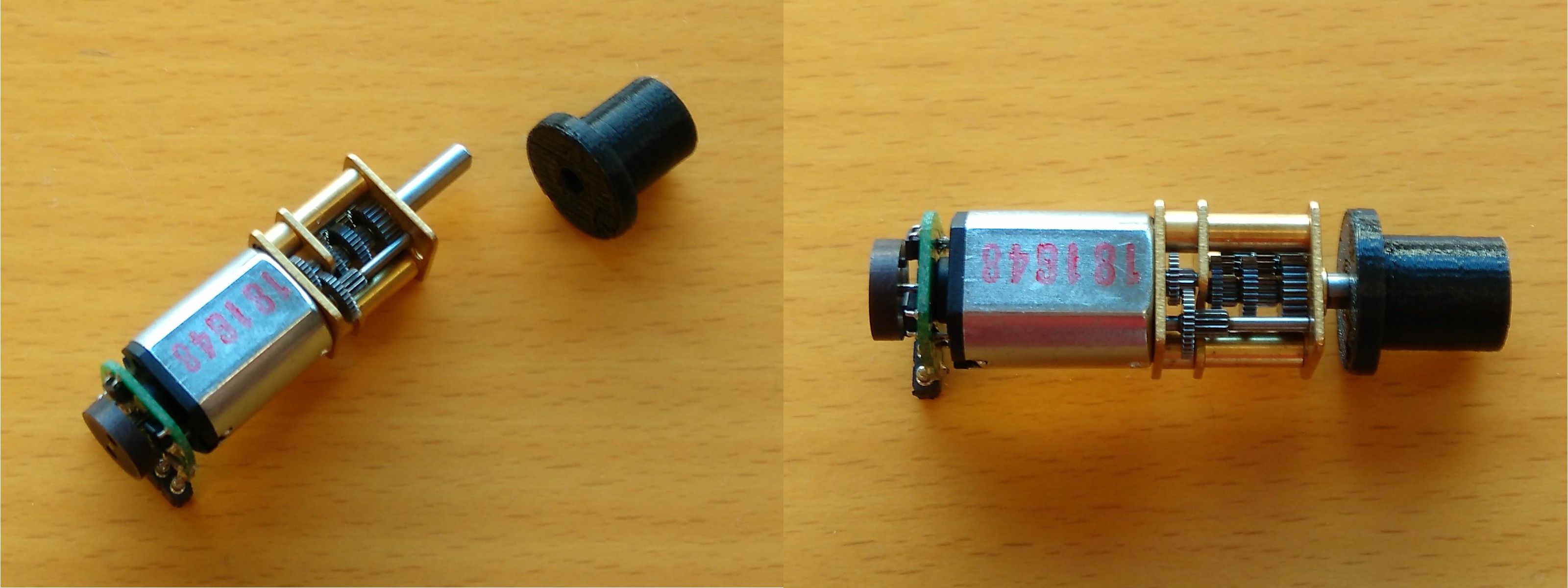
Among the different types of prosthetic hands that exist, robotic prostheses are those with greater functionality. DC motors, or other kind of actuators, drive the motion of each finger, or groups of fingers. To control this devices, EMG signals, the electric signals generated by human muscles, are the common choice as user input. However, due to their complexity and the technologies they employ, commercial robotic hand prostheses are very expensive. If their cost is already high for the average Western citizen, the problem is exacerbated in the case of developing countries where, besides having a much lower level of income, the number of amputations is greater due to several factors such as war, a poor health system and defective safety measures at work. Another group that is affected by the high cost of these devices are children, who need to change their prosthesis every so often to adapt them to their physical growth.
Dextra is another example of the growing field of open-source, replicable, robotic hand prostheses, in the spirit of the designs of the Open Hand Project or Openbionics. There is a need for low-cost and hackable prostheses, as commercial ones are very expensive and cannot be modified to suit the needs of each individual. Moreover, and from a different perspective, robotic hands for a more general purpose also suffer from the same problems than robotic hand prosthesis. Robotic hands used in humanoid robots, robotic manipulators and research have a very high cost, in many cases unaffordable for startups, small universities and research centers. The existence of robotic hands that can be built and programmed by oneself could widen the field of application of these devices. They can be used by hackers everywhere in their own projects, and they can be introduced in schools and universities to taught robotics with a real device that can be used from the assembly stage to the development of different applications.
Main features
- Replicable and modifiable.
- Completely open-source. Designed with open-source software.
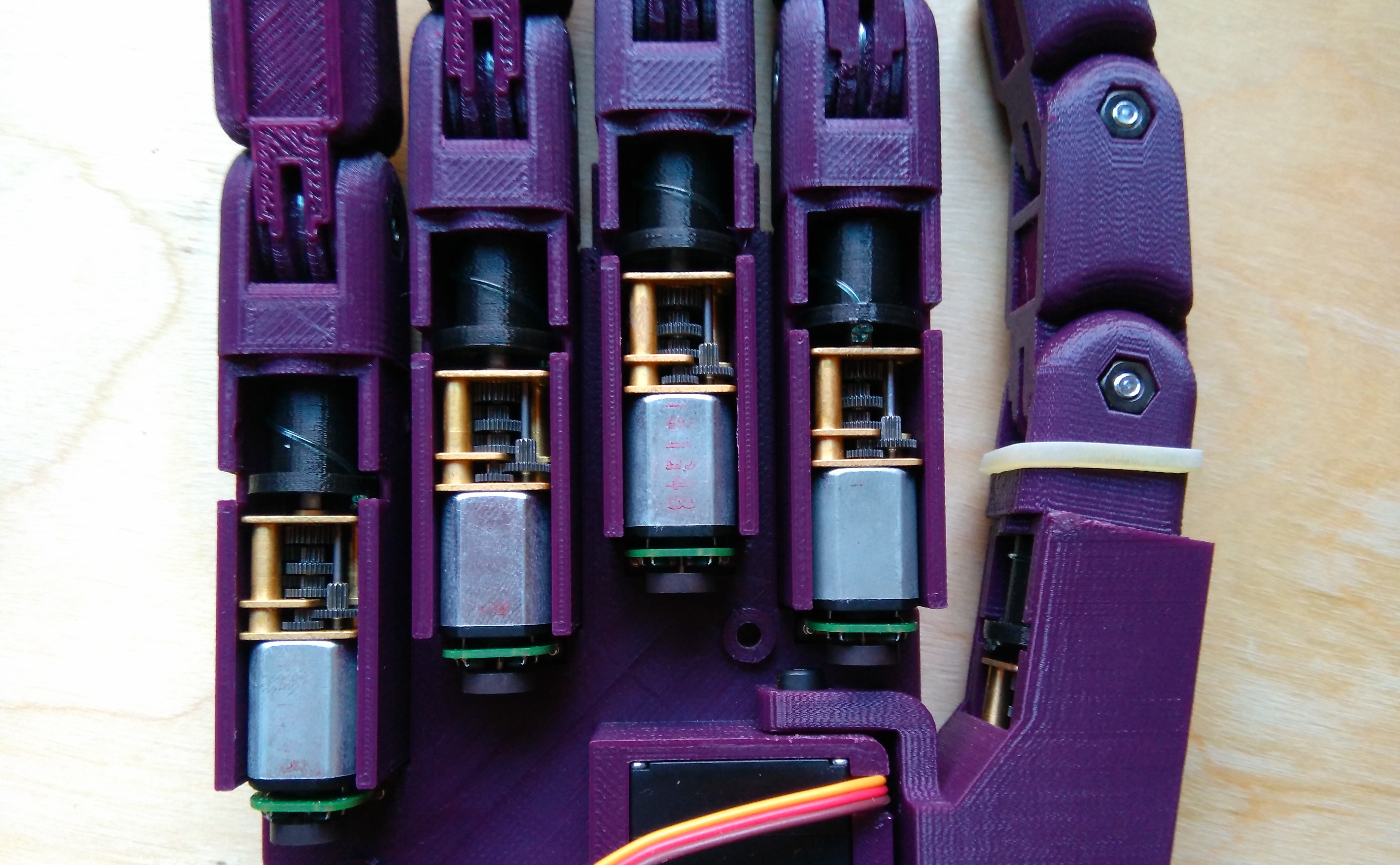
- Compact design.
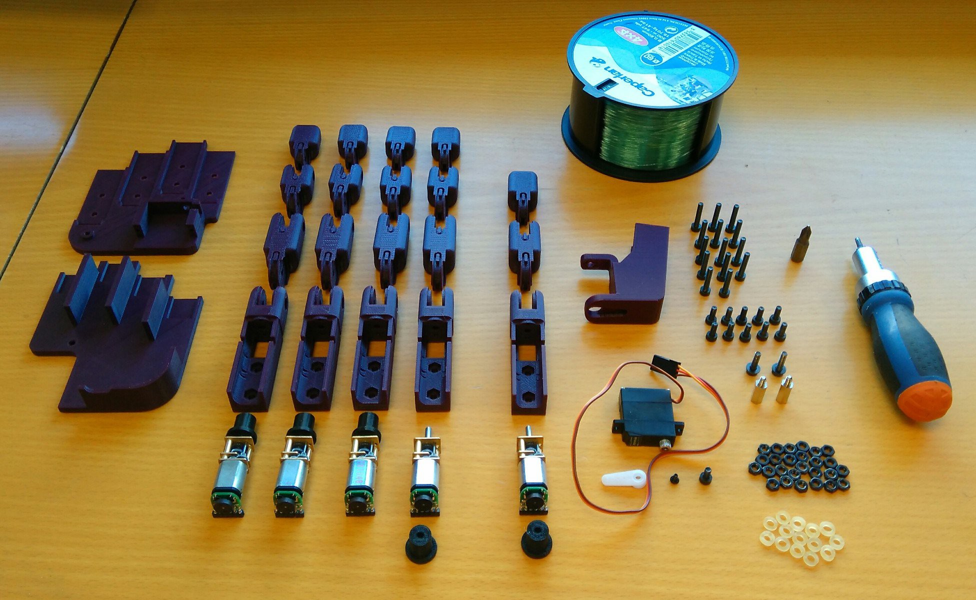
- Modular and easy to assemble.
- Underactuated fingers.
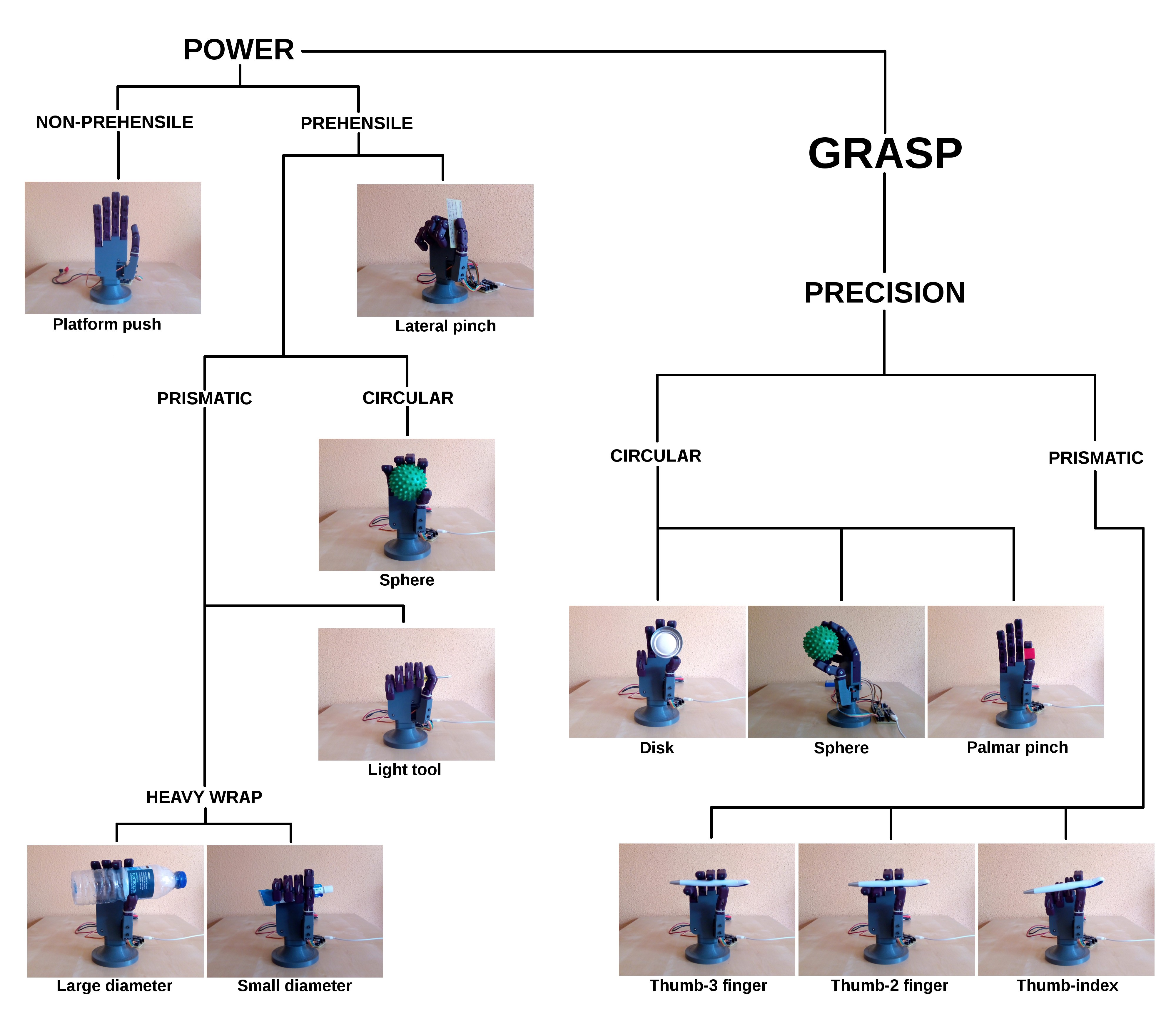
- Adaptive grips.
- Closed-loop position control.
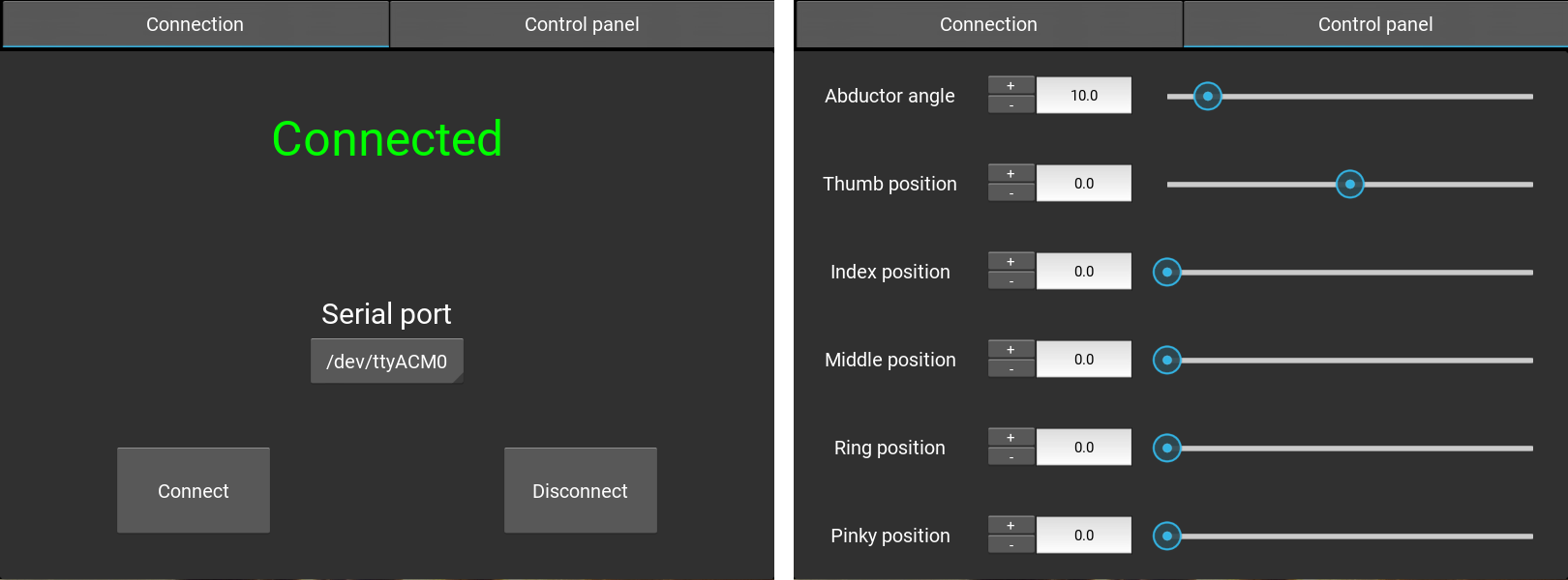
- Human-robot interfaces: EMG control and PC interface.
- Built with cheap off-the-shelf components.
- Cost to build a unit < 260$.
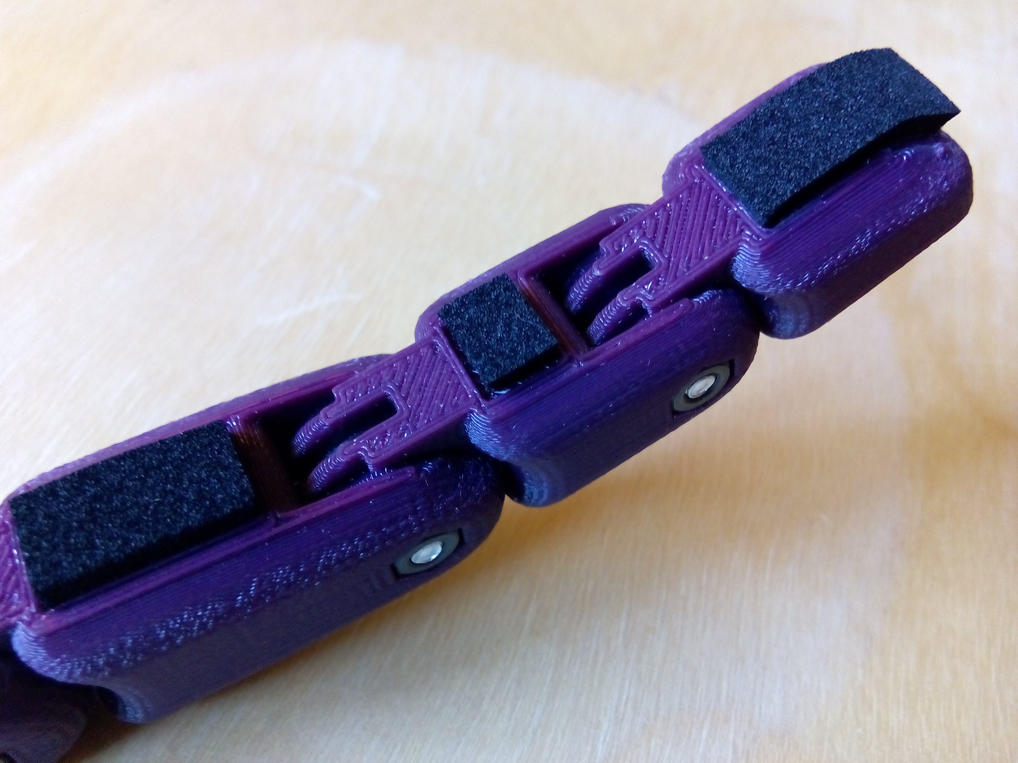
Compact design
To be accepted by the user, the prosthesis has to be close to the human hand in size and appearance. Also, to be used by any upper limb amputee,...
Read more »
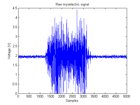 The simplest form of EMG control, and the easiest to implement in a microcontroller, is the threshold-based MCS. These controllers compare the amplitude of the EMG signals with a predefined threshold. I
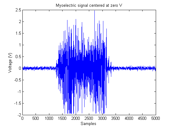 Now, rectifying the signal is just a matter of applying the abs() function...
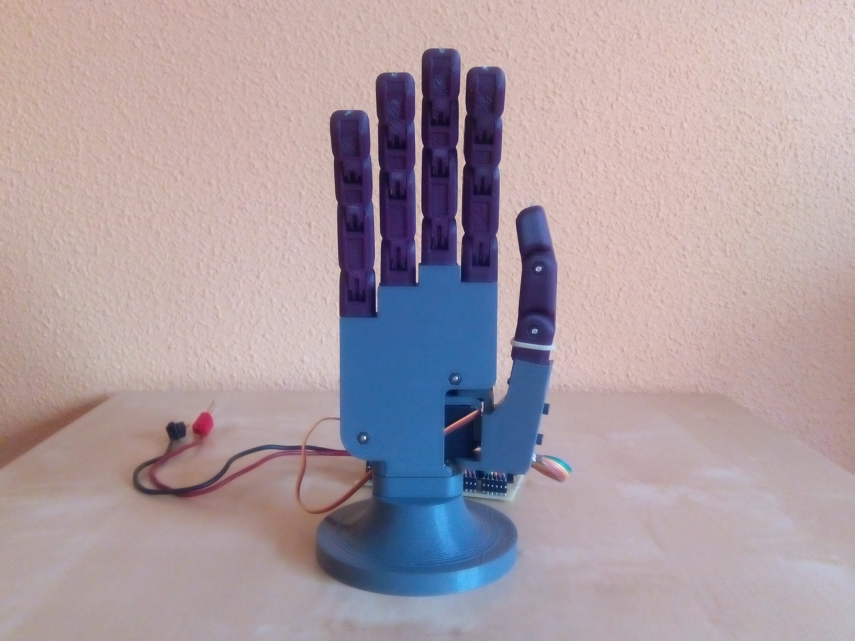


 Tamas Feher
 timlindquist
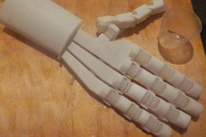
 Nelson Phillips
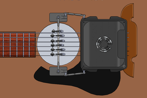
 Joe
Joe
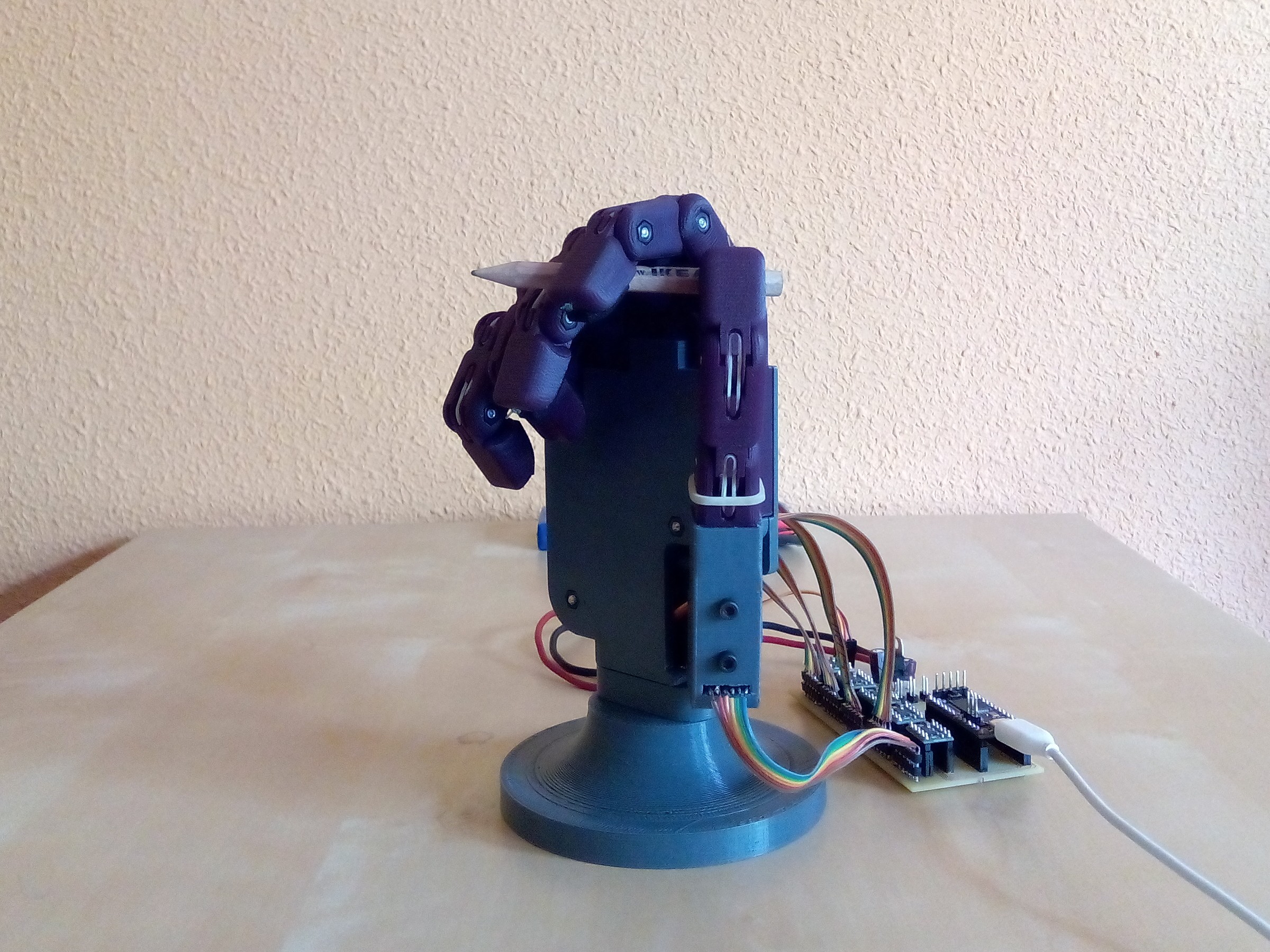
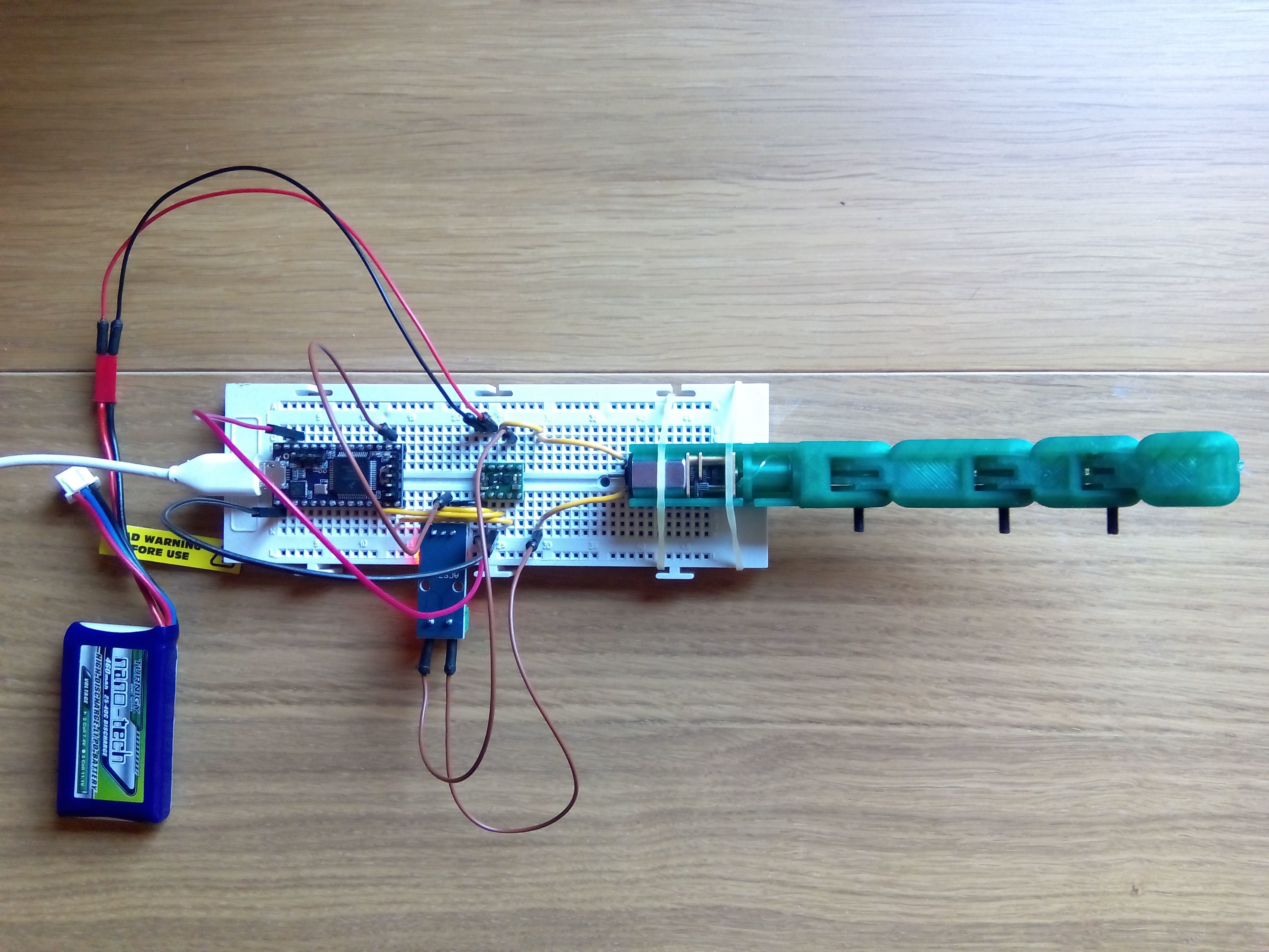
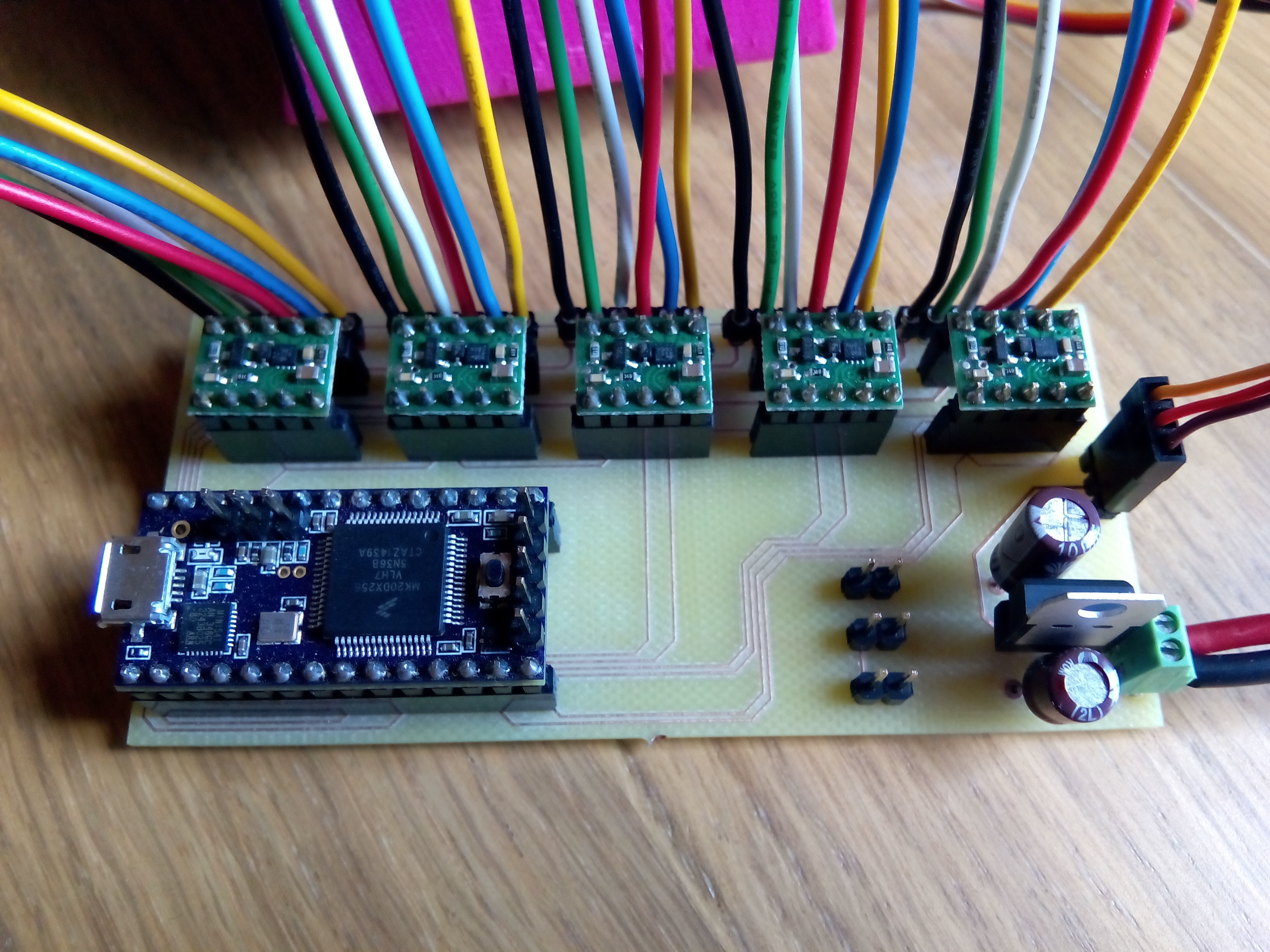
Hello! I love your design, but I'm having some trouble replicating it. I haven't worked with Teensy or with Pololu's products, so I'm a little lost on how to wire everything together. The documentation and images you posted are nice, but aren't super clear as to how to wire the Teensy to the motor carriers, and then the carriers to the motors. Would you mind sharing your circuit diagram so I could try to replicate it?