 Tamas Feher
You can explore the current state of the design through a 3D visualizer.
Click this link and give it a spin!
The famous ball balancing platform reimagined
Already have an account? Log in.
To make the experience fit your profile, pick a username and tell us what interests you.
You can explore the current state of the design through a 3D visualizer.
Click this link and give it a spin!
In the last log, we tried using Capacitive sensing to sense the ball, but that ultimately failed.
In this log, we are going to explore an inductive sensing method to detect the ball's position on the plate.
There are multiple ways to exploit inductance for proximity sensing. In this article, we will focus on the resonant sensing principle.
The sensing inductive coil and a capacitor are connected in parallel to form an LC tank circuit. The inherent resonant frequency of this circuit can be calculated as
As a conductive target approaches the inductive coil, eddy currents form on the surface of the conductive target. The magnetic field of these eddy currents resists the current of the inductive coil, which reduces the inductance of the system and increases the resonant sensing frequency.
Here is an example LC circuit with 2H of inductance
And the same example but with half the inductance
You can see that the frequency of resonance has changed and this is the property that we will measure in this experiment. You can find out more about the principle of operation in this
For testing, I'm using the TI LDC1614 high-resolution inductance to digital converter.
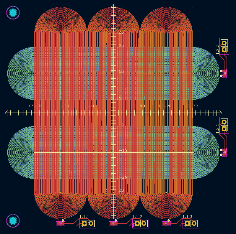
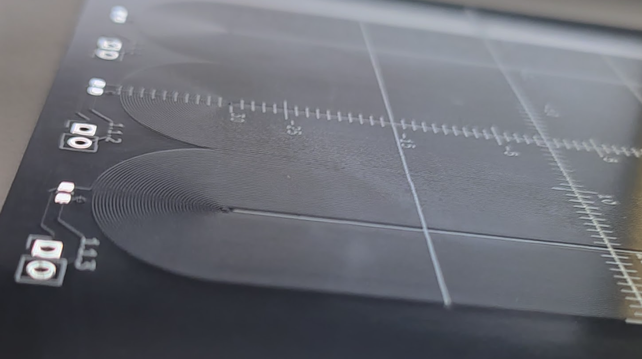
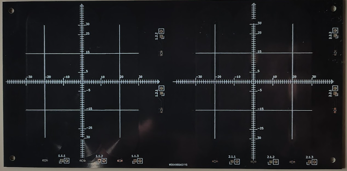
The way I chose to construct the sensing elements is by lining up multiple sensing coils next to each other. The sensing elements are spiral tracks printed on a PCB. They've been elongated into a "Horse race track" shape, so that they would be sensitive to the ball's movement only in one axis. Later tests confirmed that moving the ball alongside the racetrack doesn't influence the measurement to a significant degree.
Multiple of these tracks have been put next to each other and interlaced in different directions on a 4 layer pcb, so that we have sensing resolution in both the X and Y directions.
The final test pattern looks like a weaving pattern:
This way the vertical racetracks detect the X position by observing which coil has changed it's inductance the most. Hopefully to sub mm accuracy. Same applies to the horizontal racetracks.
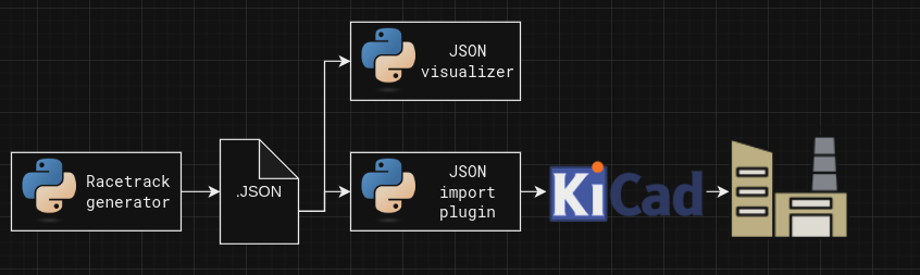
The issue with these racetracks is that there is no built in feature in KiCad (Open source electronics design software) to lay spirals out. Doing it by hand would be a grudgingly long job. Instead I opted of automating the process through python scripting.
KiCad's python scripting API is a bit difficult to use due to lack of official documentation, so I opted to offload the racetrack making into a dedicated python script, that outputs a JSON file which contains the details for all the tracks that it needs to contain. The plugin I wrote for this job takes in that json file, and imports all the primitives into KiCad. I wrote a visualizer, that enabled me to iterate on the generator without spamming KiCad with failed tracks.
Here are the results:
The big question about this side route is if we are going to be able to make enough change in the measured inductance that we can measure it well enough? Given that we have pcb coils, interviewing traces, and spherical target, instead of a flat one.
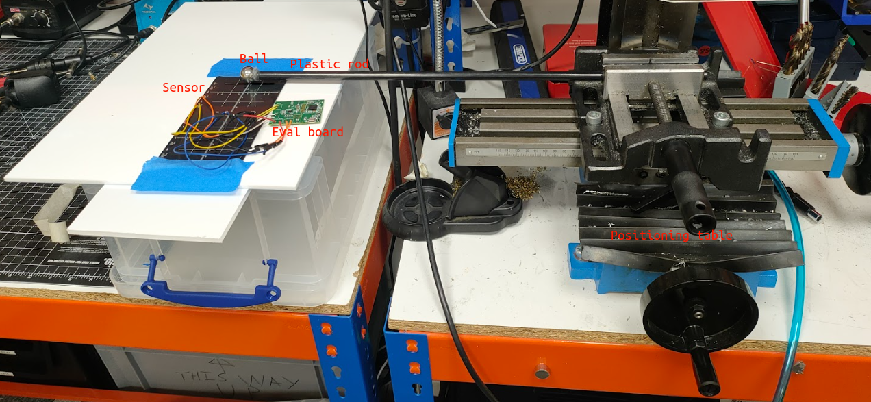
To test this I used the LDC1614EVM evaluation board and mounted the ball on a plastic rod, so it wouldn't interfere with the measurements. The plastic rod was fastened to an X-Y positioning table, that let me set the ball's position with sub mm accuracy.
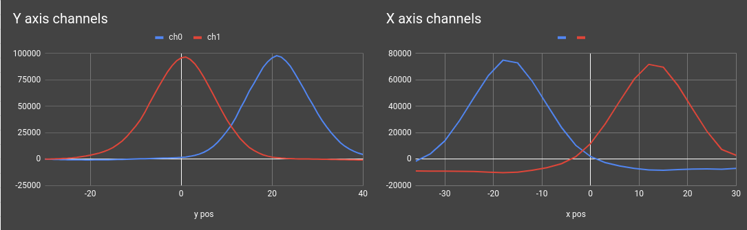
After painstakingly taking a measurement at every single millimetre and manually recording the measured value, here is what we got:
The results are promising. We are seeing a 100000 counts maximum activation on the Y axis channels, and around 75000 counts maximum activation on the X axis. With this level of resolution, i'm happy to continue exploring in this direction
In this log we've introduced inductive...
Read more »In BJR_LOG_08, we've gone through how a capacitive touch-capable PCB was designed and manufactured. In this log, we will look over how this was tested and the results of the test for use in this project.
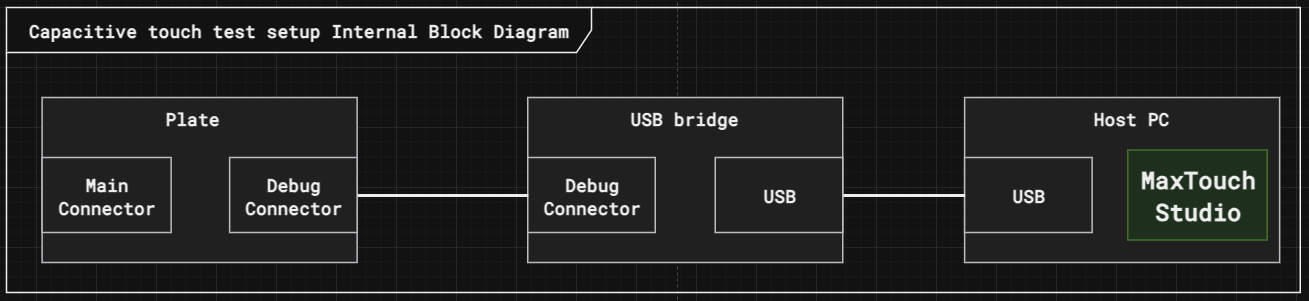
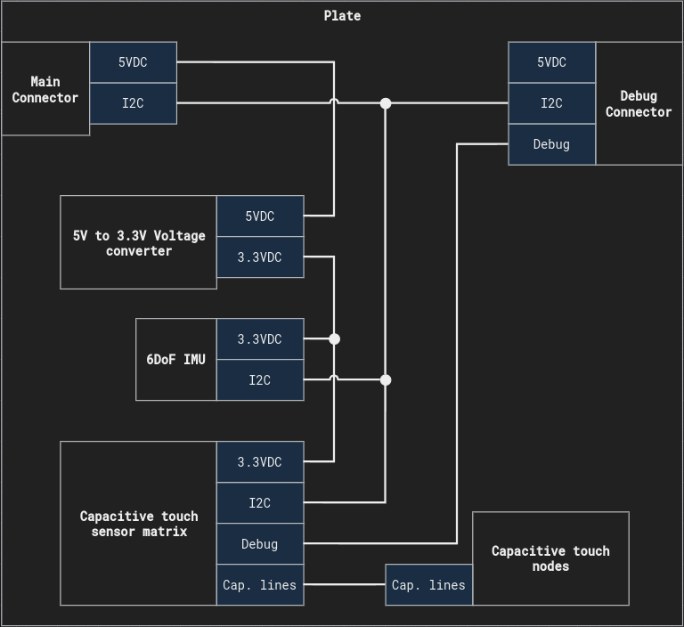
The Capacitive touch plate exposes 2 connectors. One for the main controller, which will be used in normal operation, and a debug connector designed for testing the plate.
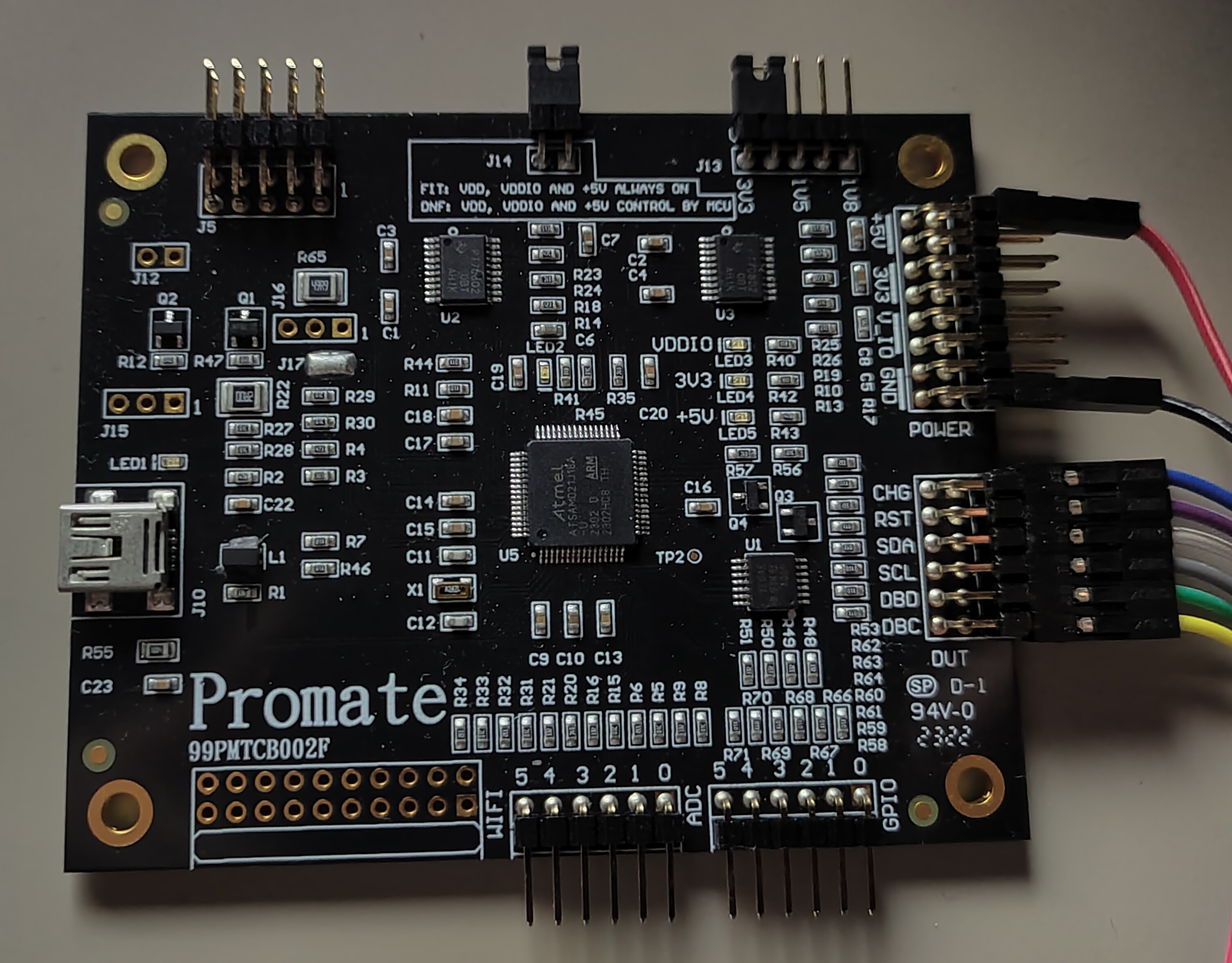
For testing, we will bypass the central controller altogether, and connect the plate to the computer through a USB bridge. The bridge is a PROMATE D21 . It's the cheapest bridge I could find at £78.22.
The reason I'm willing to spend on a device just to verify the operation of something that will be controlled through other means is the number of unknown factors. Let's say I download the I2C device driver for the MaxTouch chip, and start communicating with it through the central controller. If anything goes wrong, I have little idea whether my PCB design went wrong, my I2C bus is busted, the device driver is buggy, or my default configuration is flawed. The fewer unknown factors I expose for a test, the sooner I can conclude. By using an off-the-shelf bridge, and their tuning software, I can eliminate most of the unknown factors.
First I tested the 3.3V bus. Applying the right voltage through a test point and see if it's using the right amount of current. Then went onto the 5V source and repeated the test. Once I was confident the board wouldn't burst into flames if I connected it to the bridge I went ahead and prayed it would recognise my board. By some divine miracle, it did! No touch-ups were needed, the connection was straight-up established!
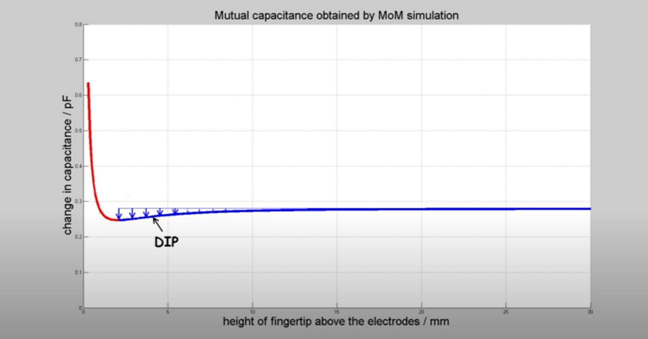
First I tested how well it detected human touch. The measurement was all over the place at the beginning. The reason for that is the mutual capacitance sensor's response to proximity. At first, the capacitance starts slowly decreasing. As the proximity reduces to near zero, the capacitance starts shooting up rapidly as seen in the graph below:
You can learn more about the physics of this phenomena in this youtube video, where I got the graph from.
The sensor only operates in the "dip" region, so to be able to detect my finger I needed to add a couple of layers of non-conducting material between the plate and my finger. (tape in my case for fine-tuning). Once the right dielectric thickness was found, the plate was working quite well to detect my finger. With a bit more work, I could have turned this into a decent touch panel.
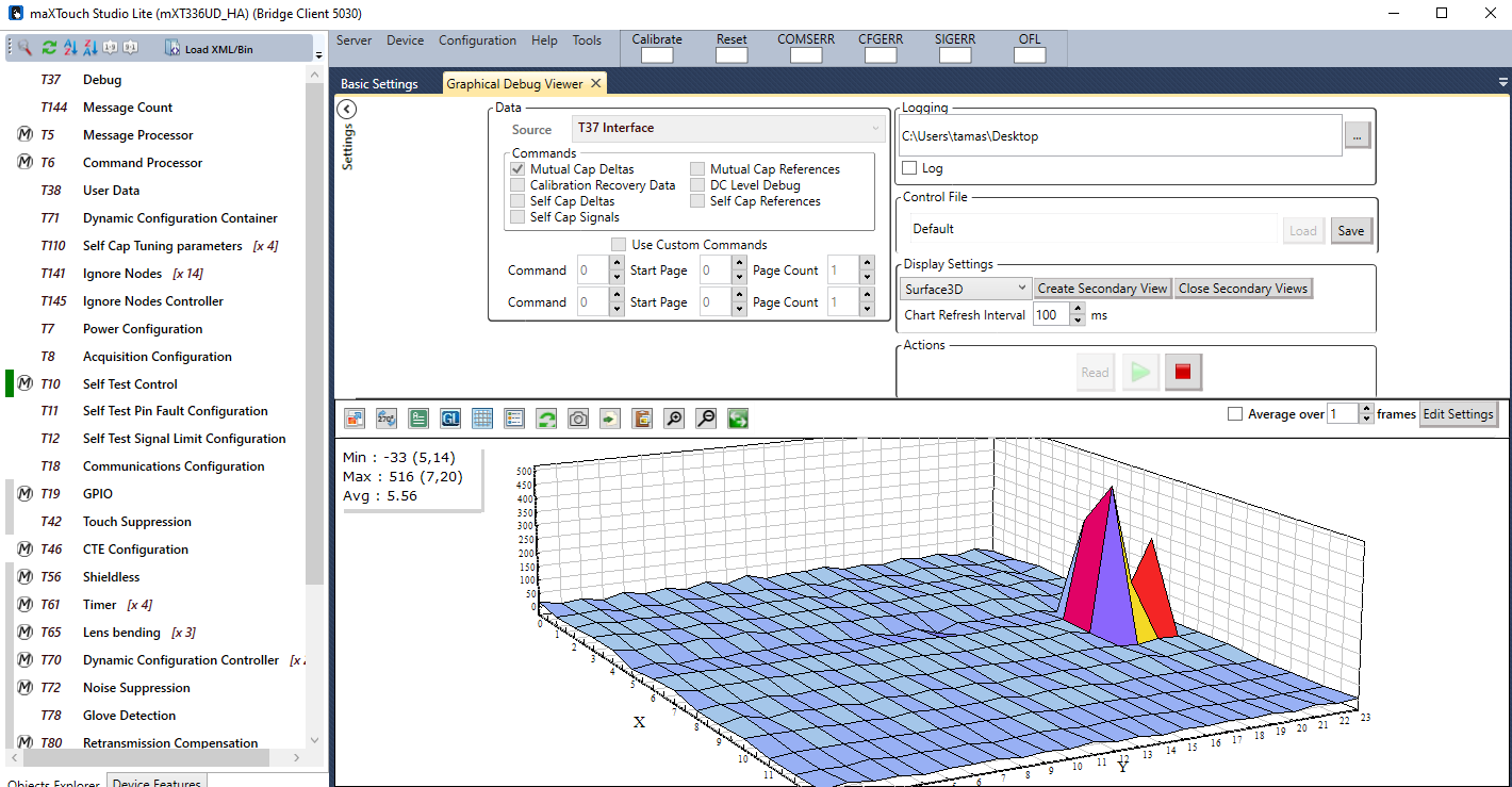
The next video shows on a surface plot what the plate recognizes from my finger:
In the next video, you will see that the response is still great even if I hold a bearing ball in my hand.
|f I'm wearing thick gloves, there is still some response, but not strong enough to be able to detect a singular touch point, so the internal filter just gives up.
Now here comes the interesting bit. If I grab the steel ball with my gloved hand, and roll it around on the sensing surface, there is still too little activation of the sensor to pick up a touch signal.
Why is that? After looking into it I found this: It's not enough for an object to be conductive to be detected by the capacitive sensor, but also needs to be able to disrupt the electrostatic field well enough so that the capacitance change is picked up by the receiver. To disrupt the field, the object would need to be either coupled to the ground or be large enough to make a dent in the electrostatic field. Sadly the bearing ball I planned to use achieves neither. If I increase the size of the ball, the signal gets better, but with the weight limit of the actuators I can't increase it large enough to be usable. This taps into the study of tangibles on capacitive touch screens. Many have tried, but most of them came to the same conclusion: It would need a human to touch the device to be...
Read more »In this log I'll introduce my first attempt at sensing the ball's X,Y position on a plate, using Capacitive touch sensing. The entire solution is self contained within a single custom PCB
In the log BJR_LOG_03 Plate subsystem breakdown I introduced the main touch sensing technologies I considered, and landed on Capacitive touch sensing. Just to recap, it operated on the basis of detecting the change in capacitance in the panel when a finger/stylus touches the surface. This technology is used in almost all smartphones, and laptop touch pads. In our use case the sensor doesn't need to be transparent, so it can be all self contained within a single PCB.
The circuit itself if fairly simple. Here is the high level overview:
I threw in an imu into the design as well to be able to compensate for uneven floor. It might not be needed in the long run, and it doesn't hurt the prototype. The debug connector helps connecting the touch controller to a computer without having to write a driver for the device.
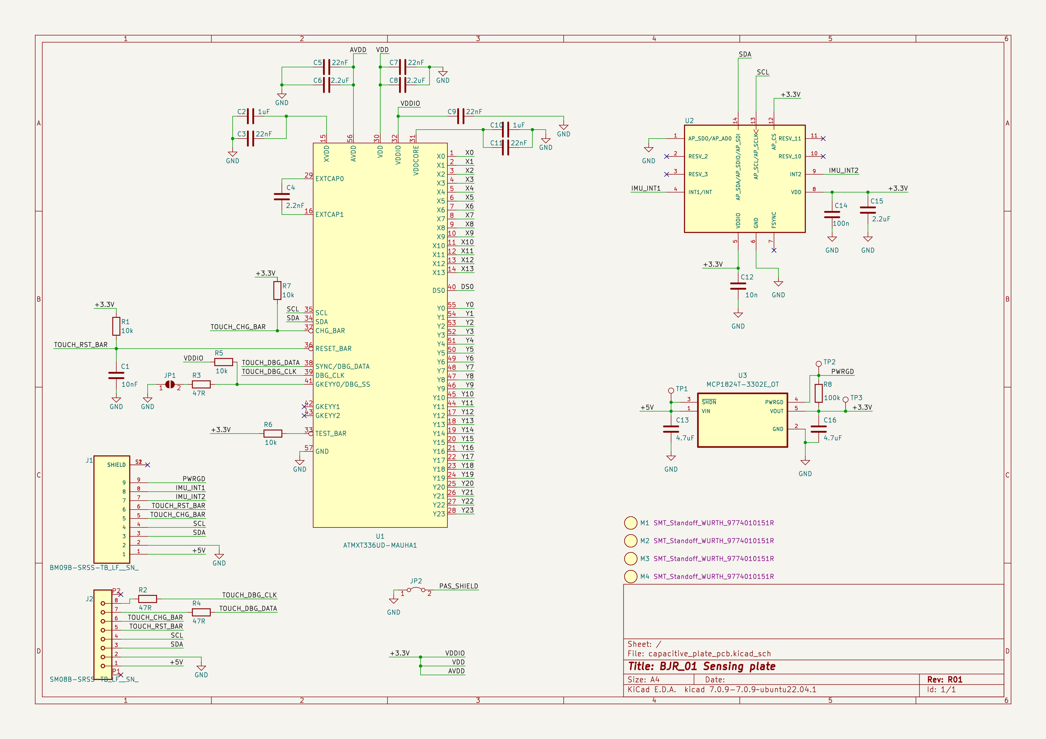
I used KiCad to create a prototype PCB that could be tested with the system. here is the schematics of it:
The main star of the assembly is the ATMXT336UD. It's a touch screen controller with 336 nodes from the maXTouch product family. It does all the measurement, signal processing, filtering, the whole bundle. It reports touch information on an I2C bus.
The sensing elements are arranged into rows and columns. The Columns are driven, and cycled through one by one. The rows are measured against the active column of sensing elements. This is how the 2d plane is covered with so many nodes.
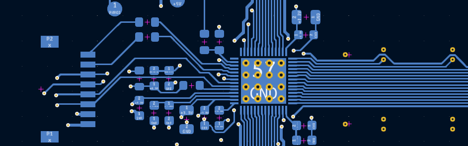
A 4 layer pcb was used, where the layers look like the following:
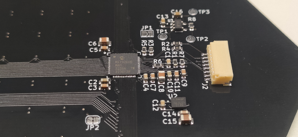
Some components had way too narrow pitch for me to comfortably hand solder it, so I asked the PCB manufacturer to populate the boards for me.
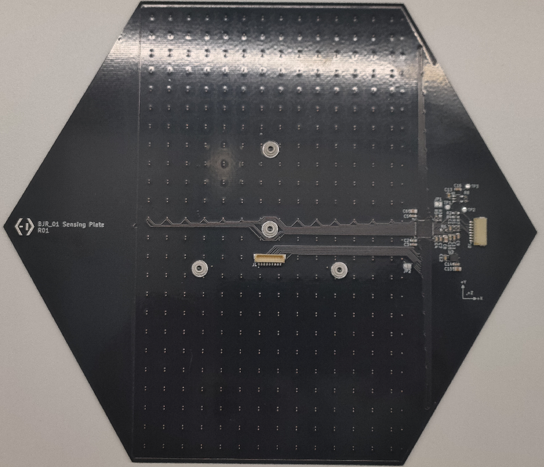
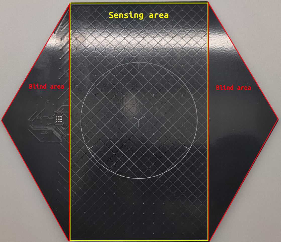
Here are some pictures of the complete board:
The sensing area is much smaller than the entire plate. The application note recommended to use rectangular footprint.
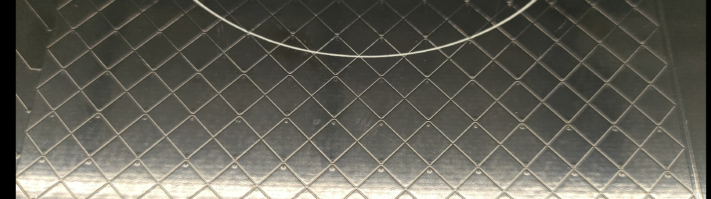
The next picture shows the diamonds sensing pattern.
This board was very much out of my comfort zone, as I've never used capacitive sensing before. Thankfully there are great resources available online which holds your hand through the design process with examples and application notes. The most useful resources for me were:
The next log will deep dive into the evaluation of this board. To give a bit of spoilers, the board Functionally works well, it detects human touch very well, however the touch of the ball yields very inconsistent results. We will see why in the next log.
Make sure to follow and like the project if you're interested how the plate operates in the target environment.
I hope this log helps show that an unfamiliar technology can be safely explored through manufacturers' application notes.
Let's look at the central control circuitry next.
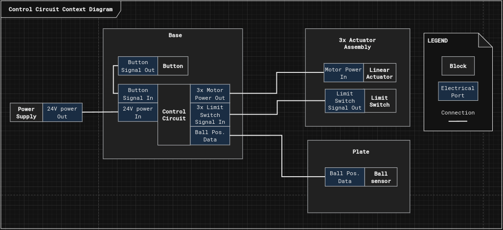
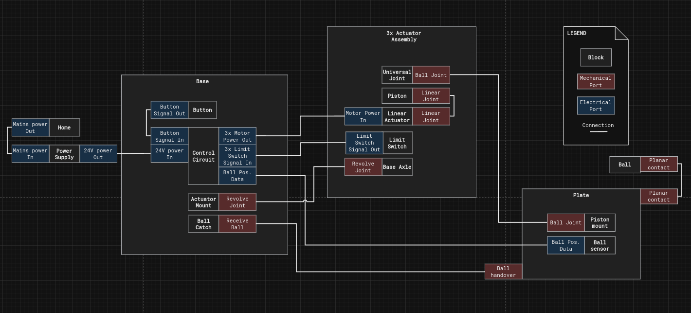
If we take a look at the subsystem breakdown in BJR_LOG_02, we can see the central control circuit already has it's inputs and outputs defined. The following figure is a context diagram, which shows the Control Circuit and it's interfacing blocks.
Let's go over the interfaces and form them into requirements:
1. The Central Control Circuit shall be powered by 24VDC power
2. The Central Control Circuit shall control 3 stepper motors with 0.6A current per winding
3. The Central Control Circuit shall listen to the input of 3 endstop NO (normally open) switches mounted at the end of the actuators.
4. The Central Control Circuit shall listen to the input a user button
5. The Central Control Circuit shall communicate with the plate through I2C protocol (It hasn't been established yet how the plate will communicate with the base, a later log will go into more details on the why and the hows.)
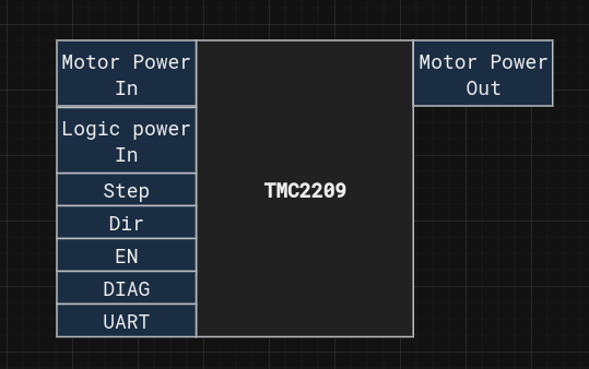
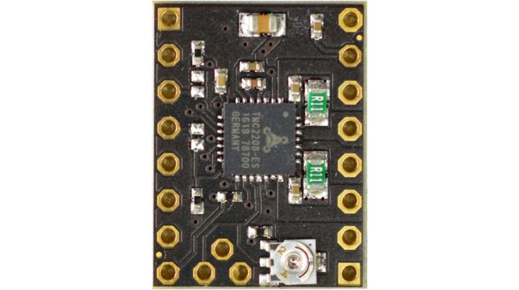
The main component that controls the stepper motors is the TMC2209. It has been selected for it's StealthChop2 and CoolStep features which provides noise free operation at lower speeds and reduced current use in idle mode, which helps with heating of the actuators.
The datasheet helps identifying the main interfaces of this device, which are:
- Motor power in: 24VDC in our case
- Logic power in: 3.3VDC in our case
- Step/Dir: traditional stepper motor driver interface, where the motor executes a step every time a falling edge is detected on the Step line. The direction of the step is determined by the Dir input.
- EN: shorts the motor coils, and disables the output. It's useful for the off state and initialisation.
- Diag: pin offers feedback to the controller if anything went wrong during operation.
- UART: is a one pin serial interface to set the drivers internal registers.
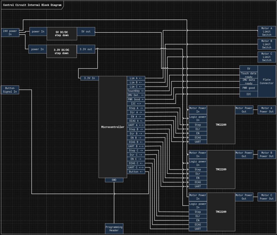
Now we have all the necessary components to devise a block diagram for the circuit:
In this circuit a single microcontroller hosts all the computation needed. Based on the block diagram it needs to be capable of hosting:
- 9 Digital outputs
- 10 Digital inputs
- 3 UART channels
- An I2C bus
- SWD programming
Given these requirements I chose the STM32F446RE microcontroller.
There is no elaborate reason why I chose this one, I just had a couple of these lying around in a drawer.
With this the Circuit is ready prototyping and the software to be started.
If you're interested in the project, give it a like, and leave a comment on what part you would like to see next.
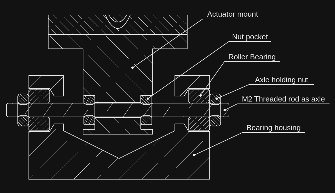
The biggest risk on the mechanical side of the project is backlash and flex in the assembly.
Backlash is difficult to account for in control systems so it's better to tackle it at the source.
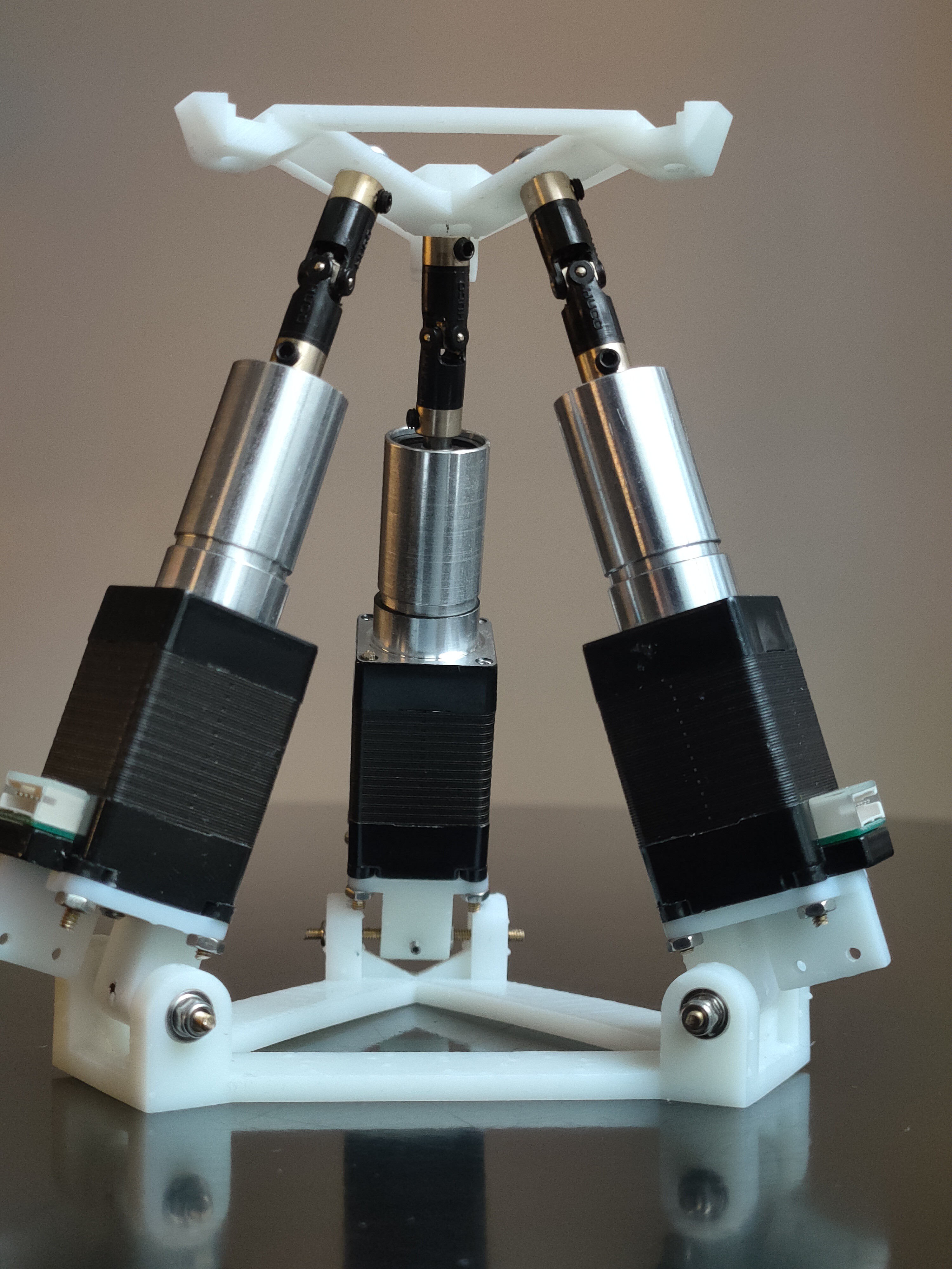
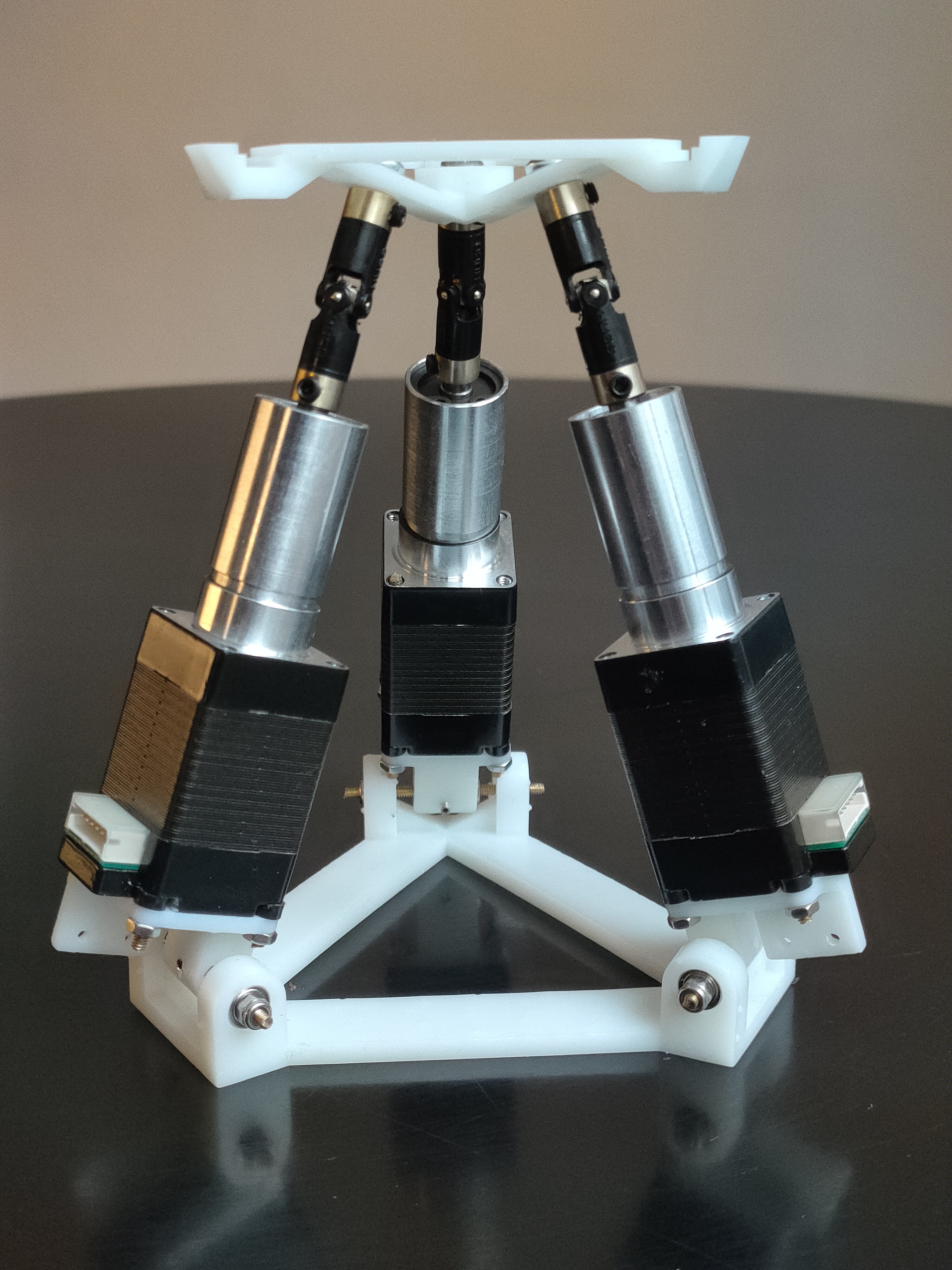
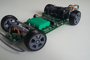
To make the build I SLA resin printed all non standard parts, here you can see the results:
There were no major issues with assembly, however there were some issues with backlash and flex. On the video you can see me stressing the assembly to see where the weak points are.
I found the following issues:
Other observations:
These issues will be tackled in the next version (BJR_02) but it's not severe enough to stop in my tracks to continue.
Now there are enough requirements available to decide on the technology used for the linear actuators. Let's recap what are the relevant requirements:
Overall this project needs actuators that are fairly quick with low force output. This gives an ideal candidate to direct drive motors.
Direct drive means no gear reduction involved in the drive train. It's beneficial in the sense as well that gear inefficiencies usually add noise to the system, while this project is aimed to be silent.
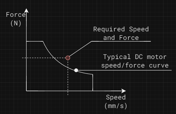
it's not enough to analyze the force and speed separately, as the actuator needs to be able to produce the prescribed force at the given speed.
The figure above shows that even though a motor is capable of delivering the needed speed and force, it might not be suitable for the application.
Let's see what technologies we would run up against each other in this trade study:
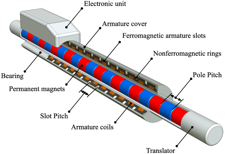
Linear motors
Linear motor technology has recently evolved a new form of motors, where the magnets are contained within a shaft, and the motor only contains the windings.
This technology enables very high-speed linear motion. The downside has been the technology did not break into the market yet, and the prices are still quite high. I was quoted over £400 (~498 USD) for a single unit.
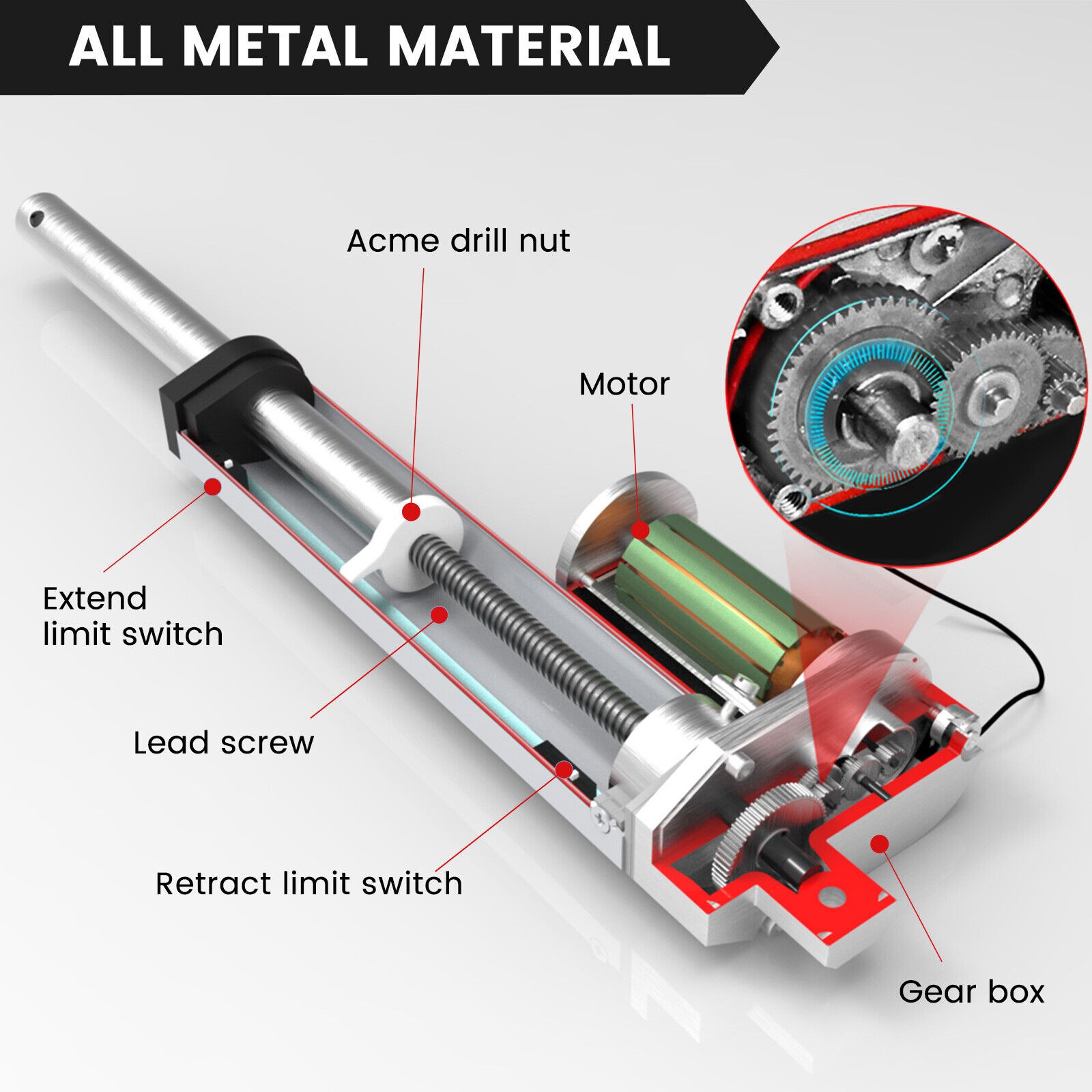
Captive linear stepper motors
That's quite a mouthful, so let's break down how these elements describe the technology.
A stepper motor is a type of motor that moves in precise, fixed steps in response to electrical signals. Linear means that the rotation is converted to linear motion, in this case with an ACME profile threaded rod.
In order to make the threaded rod move linearly, its rotation needs to be prevented with something. In this case, it's a sliding mechanism.
Captive in this case means that all the thread, the motor, the sliding mechanism is self contained within the motor assembly, outputting pure linear motion.
An example video can be seen below:
Stepper motors are famous for their silent operation. If you've ever seen a 3d printer in its works you'll see that it makes all kinds of noises. The reason for this is the stepper motors. More specifically the control of the motors. They are not inherently noisy, just they are controlled with a choppy drive signal that causes a lot of harmonics.
One product that helps us combat that is Trinamic SilentStepStick.
Trinamic's StealthChop offers nearly noise-free running of stepper motors.
Linear DC motors:
The linear DC motors work under the same principle as the captive stepper motors. This means they spin an acme threaded rod that's prevented from rotating to achieve linear motion. Often these motors contain a gear reduction, which usually injects some noise into the system. However, they are very cost efficient and easy to work with.
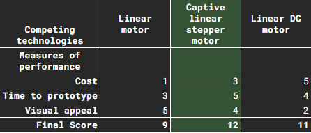
Similarly to BJR_LOG_03, I'll be using a decision matrix to decide which technology to use.
Using the same Measures of performance as before:
- Cost
- Time to prototype
- Visual (or audible) appeal
The evaluation looks like the following:
So moving forward I'll continue the design using Captive linear stepper motors for the actuator.
Steppers can be run open loop without a feedback encoder. The only issue is at startup they have no recollection of where the output actually is. To combat that a homing procedure needs to be executed, where the motor goes towards an end position, and an external switch registers when the output has arrived. For this, I'll be using a micro switch mounted at the bottom of the motor. I'll be experimenting with the stepper controller's StallGuard feature, which...
Read more »
In the next log, I will choose the motor for the actuator. To be able to do so, I will need to set some requirements. Mostly:
My way of figuring this out spawns from quadcopters (Bear with me on this).
A general (often wrong) rule of thumb when sizing the motors for a quad is to have twice the amount of thrust that's needed to hover. Why is that?
It boils down to control authority. Which means how much can you influence your controlled variable.
For your system to be effective, there needs to be enough control authority to perform the intended action, and some more to be able to compensate for disturbances. Going back to the quadcopter example: If the motors are producing a 100% thrust just to hover, they don't have enough headroom to control the tilt of the craft. Any small breeze would send it spinning, making it unstable.
That's why the output thrust is chosen to be what's needed, and some more on top of that.
Doubling the value is an easy guesstimate that can be tuned further once the prototype is ready.
In this case, we can start the analysis by looking at the most demanding use case, which is the fast circling of the ball.
The speed of circling is 200 Deg/s, and the diameter of the scribed circle is 130mm.
The linear velocity (blue arrow) of the ball can be seen changing direction, but not magnitude.
The change in velocity direction is due to centripetal acceleration (red arrow). To calculate the magnitude of this acceleration we can use this formula:
where:
Plugging the values into the equation we get a = 0.792 [m/s^2]
The ability to exert acceleration on the ball is our control authority. So this is the value we will double to give enough headroom. Giving us a = 1.584 [m/s^2]
The next topic is about how can we influence the acceleration of the ball through tilting of the plate. I will not go into the breakdown of the dynamics of a sphere rolling on a slope, but here is the formula:
Rearranging the formula we can get the maximum plate angle needed, which is 13.069 degrees.
So now we've got a requirement: The plate needs to be able to tilt +- 13.069 degrees.
Next we can analyse how fast we need to be able to tilt the plate. The plate can tilt in pitch and roll directions.
If we look at the plate from the side, we can see that during motion it tilts in a sinusoidal wave.
We can express the plate motion through this formula:
Through derivation, we can express the plate tilt angular velocity:
The upper limit of this function is where cos equals 1, meaning our maximum plate speed is the maximum plate tilt times ball angular velocity, which is 0.796 rad/s
To get the maximum plate angular acceleration, we can derivate once again:
Once again expressing the maximum value of this function by replacing sin with 1:
Plugging in the values for the equation above, we get the maximum plate angular acceleration: 2.779 rad/s^2
Now we are finished with analyzing the plate, and we can move on to analyzing the linear actuator capabilities.
Now moving on to evaluating the needed stroke length for the linear motor. for this, we need to do geometric evaluation.
We can consider the center of the plate being pinned in space, and tilting around it.
The first variable we need to figure out is where the piston attaches to the plate. you can imagine a lever here
If it attaches close to the center, the stroke length will be shorter, but larger forces need to be applied and if it's closer to the edge, the stroke length is higher, with lower forces involved.
For visual appeal, I chose a radius of 30 mm, but that can be tuned for the motor selected.
Another important factor is the minimum internal tilt...
Read more »In the earlier log, I broke down the project into smaller subsystems. This time let's analyze the first subsystem, the "Plate"
Let's narrow our options by specifying some requirements:Given the requirements, I started researching touch-based sensing technologies. I selected 3 touch-based technologies that I would like to run up against each other:
In a resistive touch screen, there are 2 conductive films separated by a thin layer of air gap. Once something applies pressure to the top film, the contact is made by the 2 conductive surfaces. opposing edges of the films are connected to electrodes, so if a voltage is applied across them, with the contact point it forms a voltage divider. The voltage can be measured and from there the touch location can be interpreted.
The benefit of this technology is that it is very simple to control and widely available. However the downside so far I've only seen rectangular units being produced, and the ball needs to be heavy enough to overcome the stiffness of the top surface.
In this case, we are interested in a capacitive touch array instead of individual touch buttons.
Capacitive touch arrays operate on the principle that a finger (or a conductive material) would disrupt the electrostatic field around the electrode, and change the capacitance between the TX and RX electrodes. This change in capacitance is recorded as a touch input.
 This is the technology used in smartphones to detect user input.
The benefit of this technology is that it can be all self-contained on a PCB, allowing any form factor. However, the downsides are that the ball needs to be conductive, and it requires more advanced PCB design.
On the edge of the touch surface, rows of infrared emitters and receivers are populated at the position of the touch, the beams are blocked by the object, registering a touch point.
 The benefit of this technology is that it does not impose any major restrictions neither on the surface, nor on the ball. The downside is that it requires a border around the perimeter of the plate, which would be visually unappealing.
As a last technology, I chose to evaluate machine vision, as it's a common technique in ball-balancing projects.
Unfortunately, it means a camera needs to be mounted high above the plate. this would impose aesthetic issues, also restricting the material selection for both the plane and the ball.
I won't go into other touch-sensing technologies such as Surface acoustic waves, or projected capacitance methods, as they go over my head way too far for me to understand them.
Now that we've set up the contesting technologies, a decision needs to be made on which one to pursue further. My usual method for this is using the decision-matrix method.
In this method, measures of performance (MoP for short) are assigned to the technologies. In this case, I chose a scale from 1 to 5, where 1 is the worst performance and 5 is the best.
Once the ratings are established for all technologies and all MoPs, the scores can be summed together. The highest-scoring technology wins.
The choice of MoPs is individual to the project and the environment, so choose your own MoPs if you would like to try this method.
I chose:...
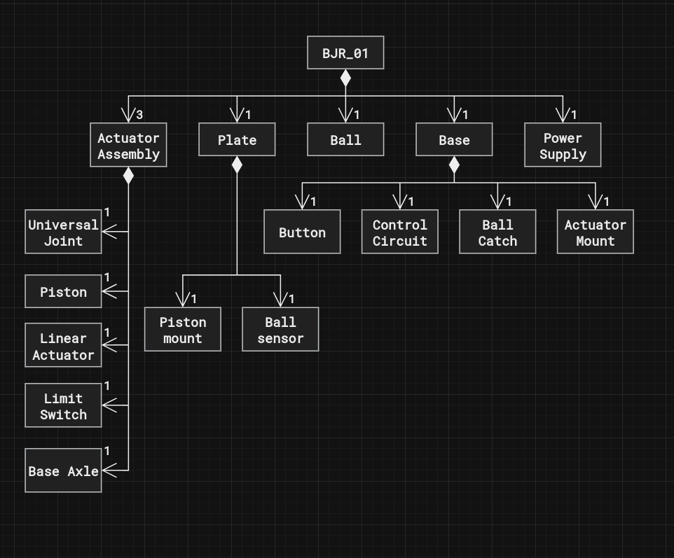
Once a set of high-level requirements was allocated, the next step is to start breaking down the project into subsystems. The next diagram shows the high level block definition diagram of the system.
Once we have the high level Items declared, the next step is to define how they interact with each other. This is usually done through the introduction of ports and connections.
I will not represent fastened connections on this diagram as it just makes the view cluttered.
The ports are represented as coloured flags attached to the blocks.
Red color means mechanincal connecitons, and blue color means electrical connections.
This view will help us when we narrow our focus to each of these elements.
The kinematic arrangement I'm using is called the 3-RPS parallel manipulator
Shout out to Aaed Musa for the great video he published on a ball balancing robot using the same arrangement. The video can be found here.
Every good project I had started with taking a moment to consider the requirements.
I know it's not the most riveting content, but it will help to set the stage for later decisions
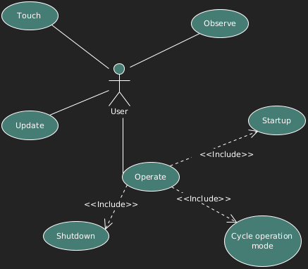
My usual approach is to identify the stakeholders and think about how they would interact with the device.
The main stakeholder is the person who would own this device, so let's start with that one.
The user would operate, observe, update, and touch the device.
The operation can be broken down into 3 other use cases:
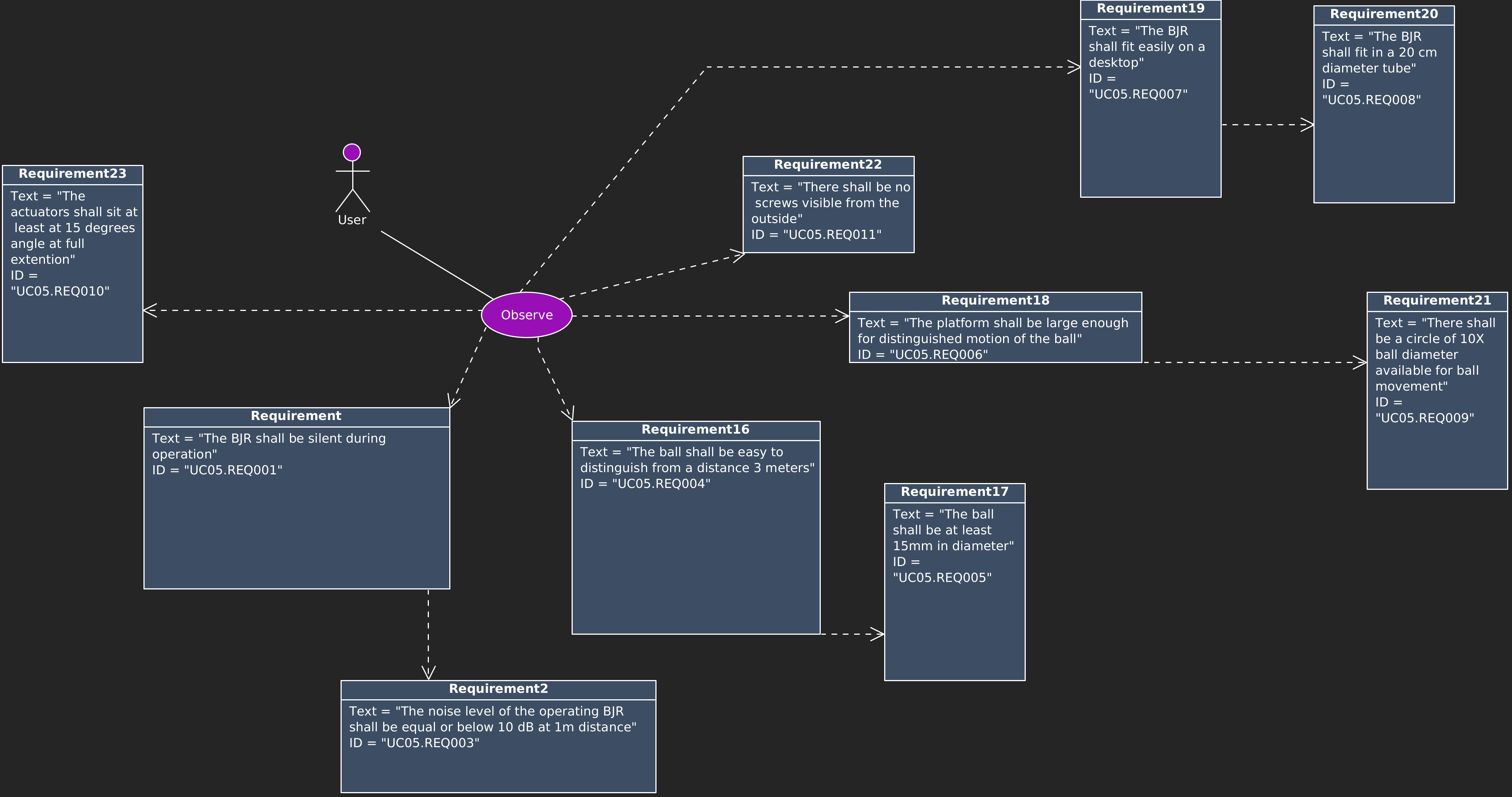
Next, we can assign requirements to the use cases.
Starting with the Observe use case, the high-level requirements are:
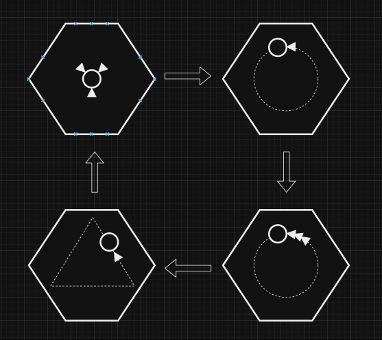
The visual intent of this project is to have a silhouette similar to this shape:
There are 4 Main operating modes:
The user can cycle these operating modes by pressing the button on the device.
To start/shut it down, the user must long press the button.
When the device finishes the start-up procedure it shall visually signal it to the user.
When the device receives a shutdown command it shall safely discard the ball from the plate if it's present. Otherwise, it would just roll off from the plate.
Let me know if you prefer more architecture building logs or want me to jump into the hardware build.

Exactly, I'll be using the ATMXT336UD capacitive touchscreen controller. Soon I'll post a couple logs on how I got to that decision and the pcb design


 AdaCore
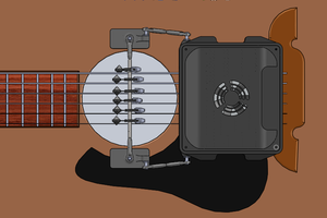
 Joe
Joe
 Peter Wasilewski
How are you going to measure the position of the ball? Some sort of capacitive sensing?