 Rob Ward
Memory was expensive in the days when the Sym-1 was released. The boards were shipped with 1kB of RAM (2 "2114" of 4bits by 1024), but could have another 6 of 2114s to be plugged in without any extra hardware required. The memory chips were not only expensive but the extra hardware of the PCB and sockets etc ramped up the price very quickly. I dutifully bought some 32kB Static RAM chips in 28pin DIL format and was setting about making a memory expansion board that could also accommodate 2764's to provide 8kB EPROM sockets, again 28DIL packages. I was half way through failing on this when I found this site Corsham Technologies where a full 64kB of RAM could be bought in a plug in and go format for the Sym-1 (and AIM and KIM). It could be paged in or out in 4kB blocks with a 16bit DIP switch, to work around where the SBC's existing RAM, ROMS or I/O were paged in. This was simply amazing!! I ordered one and it is the most highly recommended and easiest part of this project to complete. Just buy it, flick some DIP switches and plug it in. Bob Applegate has a fantastic design here. Using this I could soft load ROM images such as MS BASIC ($C000-DFFF) and RAE (Resident Assembler and Editor) ($B000-BFFF, $E000-$EFFF) into RAM and begin to feel I had a really worthwhile project on my hands.
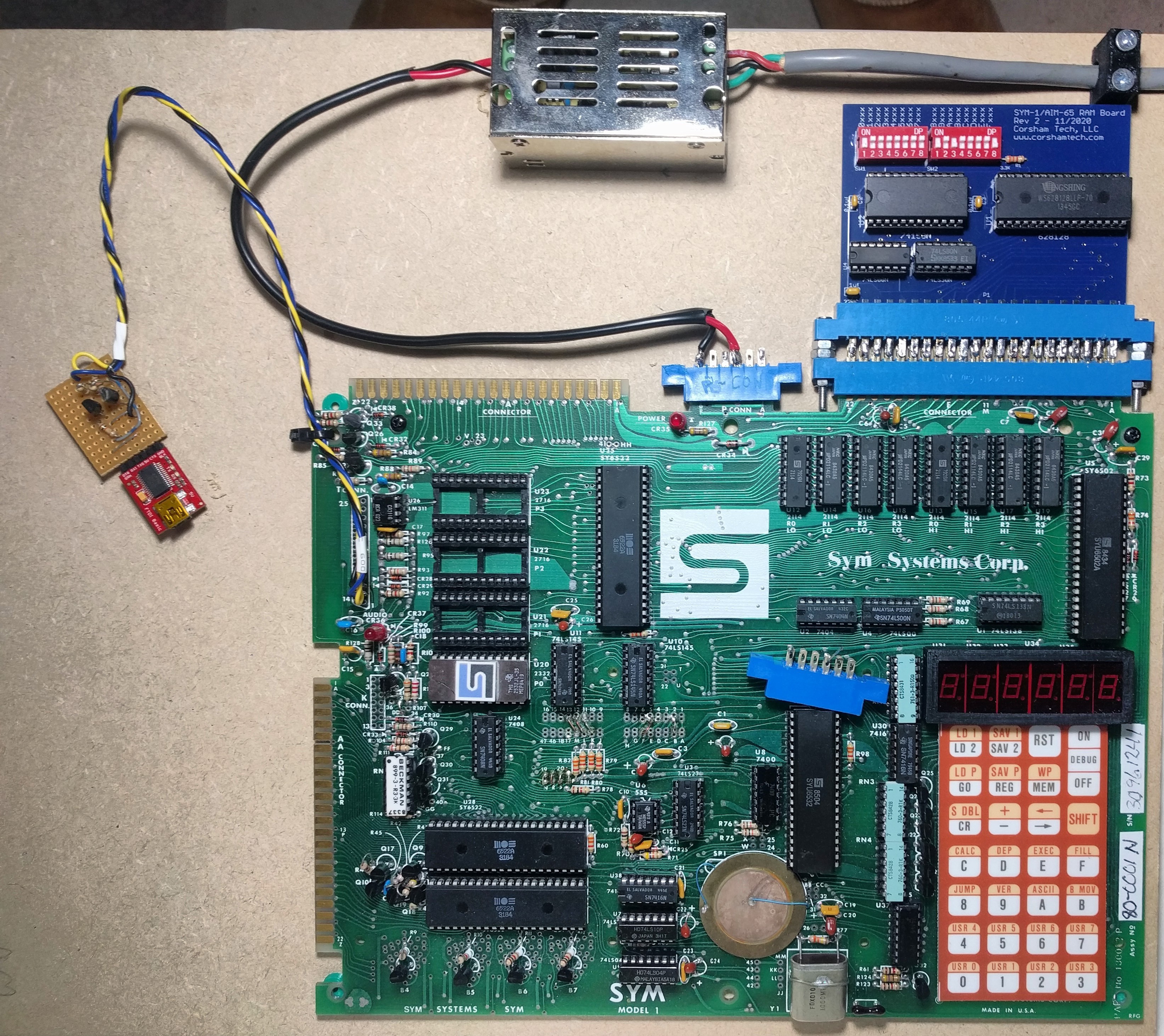
This is the board attached to the expansion E-Connector (raw Address and data bus etc). The onboard 4kB of RAM is still plugged in and the expansion RAM is switched out of that range. I have used two sockets here back to back only because I had them. I originally wanted to build a back plane for my expansion boards to plug into. So I asked Bob not to solder the connector socket onto the board as he normally did. However when I thought it through, while I could flip the board over for a back plane insertion, unless it was also upside down, the connections were mirrored :-( So I soldered two plugs together as Gender Bender hack to preserve Bob's beautiful board, but still able to connect it up. Son't much around and follow Bob's full design and just buy with the socket soldered on.
Synertek used a Paper Tape format to store data to a 1" wide paper tape punch. These could be found on the side of ASR-33 Teletypes along with a paper tape reader. These machines were a hackers delight in the day, and were treasured. However they also ran at 300baud, or about 30 character a second, so the Synertek system was able to run at 300Baud, but sadly no faster. The format had a checksum at the end of each line and most likely while the 6502 can calculate and check the checksum at 300Baud, it could not cope if the baud rate was any higher. So when I got my expansion RAM and wrote a Python script to turn Binary images into Paper Tape format, and tried to load the paper tape versions 8kB ROM images from Sym Resources at http://6502.org/trainers/synertek/ I found the speed was really painful. The 300Baud was bad enough, but because each byte was sent as two hexadecimal charcters, it made it twice as hard to bear. The second problem was the GTK-Term program that had served well up until then could not stream that many characters as characters and would always stall mid load. The answer was to use the MiniTerm Serial program that is found in the Python suite. Here is the command to trigger it off
First of all install the following:
sudo apt-get install python-serial
and then begin the TTY session with:
python3 -m serial.tools.miniterm /dev/ttyUSB0 300
This did not stall on loading the Paper Tape files at 24,576 bytes long. (Nearly 3 times longer than the original ROM image!!!). Once the Python terminal was running and the Sym-1 prompt initialised at 300Baud (reset and press Q), LP could typed and it would be expecting the paper tape reader to begin feeding in the data. To get the Python terminal to send raw bytes from the <ROM>.ptape, CTRL-T was pressed and then CTRL-U, which prompted for the filename. Press the Enter key and go away for 20-30 minutes while it loaded. At the end G C000 would start BASIC or if you loaded RAE, G B000. One neat thing about the Paper Tape format was that each line contained the address for where the following (up to 16) bytes were to go. So while the RAE ROM is split over 2 of 4kB blocks, they are not contiguous. So half of it loads into $B000-BFFF, and the second half loads into $E000-EFFF. As long as the paper tape is configured properly, this jump is taken care of automatically. However when I was burning this into an EPROM, I found there is more to add to this story. (Memory Allocation)
Another major hurdle was getting the 28pin EPROMs to work with the 24pin sockets on the Sym-1. Synertek had envisaged using 8kB ROMs, and with one chip enable, there is enough pins in a 24 DIP socket to handle 8kB. However an EPROM needs a programming pin and pin to supply the programming voltage, in this case 12.5V. So and 8kB EPROM is usually fitted into a 28pin package. I wanted to have RAE in ROM on the board, so I really wanted to be able use those 2764 EPROMs.
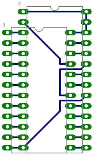
I found an image of how to map 28pin EPROM to 24pin ROM and made one up using perf-board (Vero) and some thin wire-wrap wire. There a few tricks to making these boards that I will pass on shortly...
For the project overview and support files Project Page Sym-1 A 6502 Phoenix!
Discussions
Become a Hackaday.io Member
Create an account to leave a comment. Already have an account? Log In.