-
NASA Orion and Artemis heat shields
10/25/2020 at 20:39 • 0 comments![]()
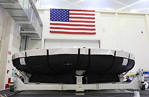
The 16.5 foot diameter Artemis heat shield (Image from NASA/Glenn Benson)
I had visited NASA’s Kennedy Space Center (KSC) in Florida where I had the pleasure of touring the Thermal Protection System Facility (TPSF) Annex run by Jacobs Space Operation Group. Martin Wilson gave me a guided tour. Wilson has a wealth of experience working with a variety of materials that were used on NASA’s Space Shuttle fleet which last flew in 2011.
Wilson, working in this field since the early 90s, has also developed thermal protection for the Orion spacecraft as well as the Artemis program. Advanced heat resistant materials are needed to protect the space vehicles upon re-entry back into the Earth’s atmosphere.
A lightweight surprise
The Space shuttle heat protection tiles weighed approximately 9 pounds per cubic foot. In his lab, Wilson picked up an Orion heat shield tile and said “catch” while he tossed it to me. I braced myself to catch a heavy tile, but when I caught it, the tile was as light as a piece of Styrofoam! Wilson was able to creatively manufacture these new tiles which would add far less weight than previous designs.
![]()
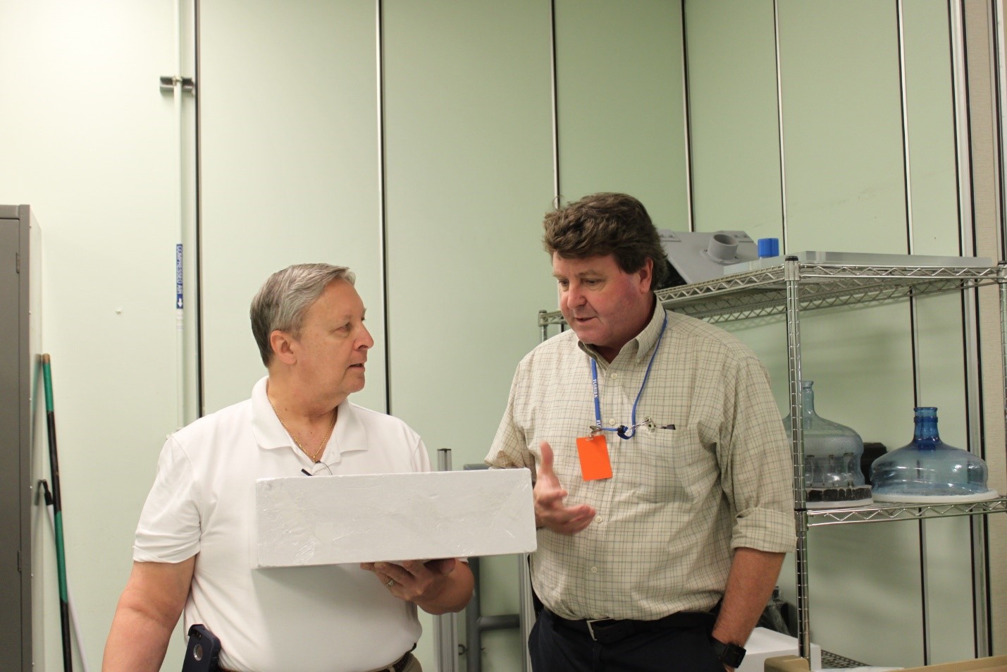
Figure 1 Thermal protection expert Martin Wilson is shown here on the right and Steve Taranovich is on the left of this photo holding a surprisingly lightweight Thermal demo tile that will be shaped to fit on the sides and top of the conical Orion spacecraft. (Image from Loretta Taranovich)
The Space Shuttle heat shielding
During re-entry, the Space Shuttle endured temperatures as high as 3,000 degrees F (1,650 degrees C) into Earth’s atmosphere.
The Space Shuttle tiles varied in thickness from 1 inch (2.54 centimeters [cm]) to 5 inches (12.7 cm) depending on the heating to which they would be subjected. The silica tile material is referred to as LI-900. It insulates heat so well that tiles can be held bare-handed on one side even while the opposite side is still red hot. LI-900 has a density of 9 pounds per cubic foot (144.2 kilograms per cubic meter [kg/m³]). They are made from pure silica glass fibers, but 94 percent of the volume of each tile is pure air, making each tile fairly light and strong!
Approximately 24,300 tiles were installed on each Space Shuttle, and each tile was designed to survive 100 trips to space and back.
Orion’s heat shield takes the brunt of the heat upon re-entry
In a new process, several large blocks of an ablative material called Avcoat, which is licensed from Boston-based Textron Systems, were produced at the Michoud Assembly Facility in New Orleans by Lockheed Martin. These blocks were shipped to Kennedy Space Center, where Lockheed Martin technicians machined them into more than 186 unique blocks and bonded them to the heat shield's surface.
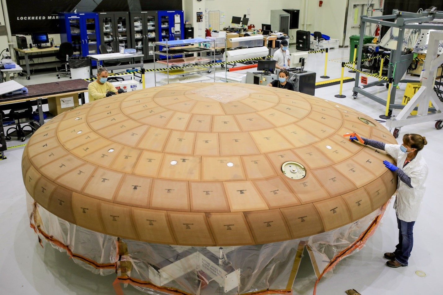
The ablative material known as “Avcoat” were machined into 186 unique smaller blocks, and then applied by technicians onto the 16.5-foot-diameter (5-meter) heat shield’s underlying titanium skeleton and carbon-fiber skin.
![]()
Figure 2 Orion's new heat shield, for the Artemis-2 mission, is the largest of its kind developed for missions that will carry astronauts. The heat shield base structure has a titanium truss covered with a composite substrate skin composed of layers of carbon fiber material. (Image from NASA)
To fill tiny gaps between these blocks, the seams needed to be filled with a mixture, which over time, would become solid. Technicians then applied a coat of white epoxy paint to the heat shield's surface and also applied aluminized tape after the painted surface dried. The tape provides surface resistivity and will absorb solar heat and infrared emissions.
NASA chose an ablative heat shield which will slowly burn off since it is able to handle higher temperatures than the Space Shuttle tiles which were re-usable.
Unlike the Space Shuttle and other low-Earth-orbiting vehicles, which begin their entry into the atmosphere at close...
Read more -
NASA “Tipping Point” technology
10/18/2020 at 21:39 • 0 comments![]()
Early in 2020, NASA’s Space Technology Mission Directorate (STMD) prioritized funding opportunities for public-private partnerships to achieve goals that would expand capabilities and opportunities in space. This effort will increase collaboration with the commercial space sector to leverage emerging markets and meet NASA's strategic goals. NASA's investment in industry partnerships will reduce development costs and accelerate the deployment of emerging space system capabilities.
Just recently, NASA selected 14 companies to develop varied technologies to foster a sustainable Artemis program on the Moon by 2030. One of these companies is called Astrobotic Technology which was given $5.8M. The company will demonstrate a fast, wireless charging system that will address the challenges associated with using that technology on the Moon. The effort will build and deliver flight units for potential use on commercial robotic landers. Astrobotic will collaborate with NASA Glenn and has teamed with WiBotic of Seattle to begin developing this technology.
Wireless charging in space and on the Moon involves wireless transmission for power systems whose mechanical connections, if used, would be prone to getting clogged with lunar dust. Wireless systems never mechanically wear out! Figure 1.
![]()
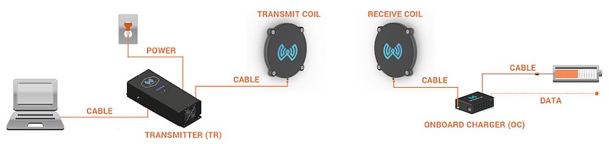
Figure 1 WiBotic wireless charging systems consist of four primary hardware components: Transmitter Unit, Transmitter Antenna Coil, Onboard Charger Unit, Receive Antenna Coil (Image from WiBotic)
For the system to deliver wireless power, the Transmitter will first check to be sure a robot is within range. The system is so flexible that even robots with completely different battery voltages can share the same Transmitter Unit. It automatically recognizes each robot and adjusts charge parameters accordingly.
The components allow for extremely effective charging station deployment. The stations deliver power opportunistically to keep robots topped off and operating for long periods. This is much better than the outdated “full drain and recharge strategy” seen elsewhere.
WiBotic will deliver the power behind autonomous vehicle operations on the Moon. These rovers can get a fast wireless charge when near any number of wireless charging stations situated around the Moon’s surface. Rovers do not have to mechanically connect to these stations, the wireless proximity charging allows rovers to get a quick charge for maximum rover uptime or a longer charge when needed so that they will be able to perform their tasks almost continuously around the clock (i.e. the Lunar clock)
Applications for wireless power on the Moon
Applications that will need proximity chargers on the Moon include the marsupial roving missions, for robotic systems that have no onboard nuclear or solar power generators, charging toolkits on crewed lunar terrain vehicles, and powering the heaters of critical devices to survive the cold, cold lunar night. Temperatures on the Moon are very hot in the daytime, about +100 degrees C. At night, the lunar surface gets very cold, as cold as -173 degrees C. Figure 2.
![]()
Figure 2 NASA's Axelrover is a whirling robot designed for the very challenging terrain on the Moon and beyond. NASA refers to a robot like the Axel rover as a 'tethered marsupial rover' because it would spend most of its time attached to a larger vehicle (Like a baby kangaroo in its mother’s pouch) until it is needed. (Image from NASA/JPL)
Here is a video of an older Astrobotic rover for the Moon at NASA’s Glenn research center. It is an old 2013 video but it gives a great example of what these rovers can do.
Astrobotic is basically developing custom designs, sensor systems, and rovers for planetary surface missions on the Moon, later on Mars and maybe even an asteroid or two. These rovers will autonomously explore, engage in site preparations, as well as resource extraction. The rovers will have co-location technology...
Read more -
NASA water recycling on the ISS can help people on Earth too
10/14/2020 at 00:36 • 0 comments![]()
A difficult problem NASA has faced since the early days of space travel is the need to efficiently filter water. There is a huge cost to carry water into space: When blasting off from a Kennedy Space Center launch pad, the rocket must overcome and escape Earth’s gravity pull. Every pound counts and contributes to more rocket fuel needed to break free of Earth’s gravity pull. Water costs $10,000 per pound and one gallon of water weighs 8.33 pounds! Since astronauts are limited to three gallons a day that costs $249,000 each day---per astronaut. To mitigate this problem, all types of moisture must be recycled into drinking water aboard any spacecraft.
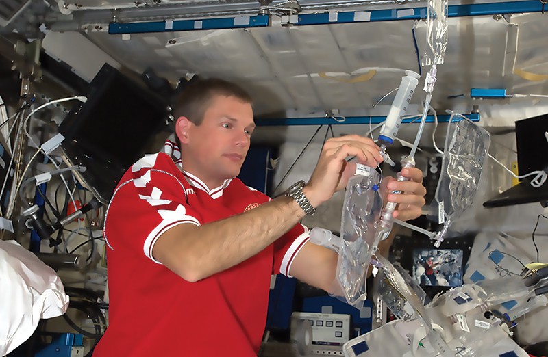
I met an astronaut at NASA Ames Research Center in California during a visit to a laboratory there working on a unique water filtration system. The astronaut met me with a beacon of urine in one hand and a cup of coffee in the other. His comment, with a big smile was, “On the International Space Station (ISS), tonight’s urine is tomorrow morning’s coffee!”
On the ISS, every drop of moisture, from humidity to urine, is filtered, purified, and reused. However, the current system depends heavy upon specialized filtration beds that weigh down resupply missions and need to be swapped out every 90 days. This system unfortunately fails to filter out certain semi-volatile contaminants.
The Advanced Water Recycling group at NASA’s Ames Research Center, developed a possible unique solution which does the job and can ultimately lead to a smaller, low-cost, light weight solution for the ISS and other future endeavors to the Moon and Mars and beyond. Figure 1.
![]()
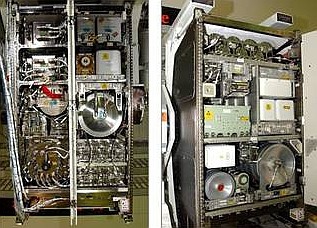
Figure 1 The water recovery component of the Environmental Control and Life Support System or ECLSS (Image from NASA)
There are two key components which make up the ISS Regenerative ECLSS: The Water Recovery System, or WRS, and the Oxygen Generation System, or OGS. The WRS conducts the water purification and filtration process in the ECLSS. From this WRS, commercial companies accessed this technology from NASA and began to adapt it to a simpler Earth-based water treatment system for areas around the world with no access to drinkable water.
NASA's previous research provided the Microbial Check Valve, or MCV, an integral component of the purification and filtration process. This is an iodinated-resin which provides a basic means of controlling microbial growth in water without using any power. By dispensing iodine into the water, an important secondary nutritional function for the populace is an added benefit. This chemical, when added to the diet, is known to promote proper brain functions and maintain bodily hormone levels to regulate cell development and growth. Children who lack iodine in their diets can exhibit growth mental retardation.
There are many, many other people around the world who are forced to use water contaminated by livestock that they sift through a cloth fabric to remove dirt and debris. Clean water, for many people, is too far away from villages which makes transporting that water to their village virtually impossible. See Figure 2.
![]()
Figure 2 Shown here are volunteers installing and testing a water purification system in Kendala, Iraq. The Microbial Check Valve is in action here (Image from Concern for Kids)
Mimicking human kidneys
Peter Holme Jensen, CEO and cofounder of the company Aquaporin A/S, commented “Nature is our biggest R&D lab. Whatever discoveries nature has made, they’re quite efficient.” Jensen met Michael Flynn, the lead for the Advanced Water Recycling group at NASA’s Ames Research Center. Flynn introduced a possible solution on which he and his NASA colleagues had been working.
The project was to develop a water filtration system based on aquaporins—the proteins that all living cells use to transfer water through their membranes. Aquaporins enable plant roots to absorb water from soil and also for human kidneys, to filter about 45 gallons of...
Read more -
Firing a laser beam to the Moon and back to Earth
10/01/2020 at 22:56 • 0 comments![]()
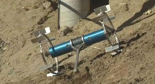
During the Apollo 11 Moon mission in 1969, astronaut Buzz Aldrin placed two experiments on the moon during an extravehicular activity. See Figure 1.
![]()
Figure 1 In astronaut Buzz Aldrin’s left hand is a seismic experiment, and in his right is a laser-reflecting panel (Image from NASA)
The reflectors on the Moon’s surface are the last working science experiment from the Apollo program. Each of these reflectors contain cubes created from the corners of glass cubes which function like mirrors reflecting light back in a multi-directional manner.
Why did NASA do this experiment?
This was a fairly straightforward experiment: Just aim a beam of light at the reflector and clock the amount of time it takes for the light to return to Earth. Decades of making this one measurement has led to major discoveries.
One of the biggest discoveries is that the Earth and Moon are slowly drifting apart at the rate which our fingernails grow, or 1.5 inches (3.8 centimeters) per year. This widening gap is the result of gravitational interactions between the two bodies of the Earth and the Moon.
The older, larger reflectors on the lunar surface are sending weak signals, which are only able to return about a tenth of what NASA had expected. Scientists think that this might be due to dust which has collected on the five panels over time. These reflectors are only the size of a paperback novel about 240,000 miles (385,000 kilometers) away from Earth. Figure 2.
![]()
Figure 2 A reflector placed on the Moon during the Apollo 14 mission in 1971 (Image from NASA)
Mostly, dust particles are due to micrometeorites frequently impacting the Moon’s surface, sending up dust that then settles back down on the surface of the Moon and on the mirrors as well. Dust will not only block light from the mirrors, but can act as an insulating layer which will cause the reflectors to overheat.
Testing the signal strength of the pristine reflector on NASA's Lunar Reconnaissance Orbiter can help scientists determine what is happening with the reflectors on the Moon’s surface. Thus far, the science team isn't sure if it is dust. But this successful signal is only a beginning to learning what is happening on the Moon's reflectors.
Erwan Mazarico, a planetary scientist at NASA’s Goddard Space Flight Center in Maryland said “Laser-ranging science is a long game.”
There is also a reflector mounted on the Lunar Reconnaissance Orbiter (LRO), a spacecraft that has been studying the Moon from its orbit since 2009. Engineers placed the reflector on the LRO because it was a pristine target to help test the reflecting power of those panels left on the Moon’s surface about 50 years ago. This reflector is smaller than the reflectors on the Moon and since it is on the LRO moving much faster than the Moon, the chance of hitting it and receiving a signal back is even smaller.
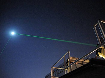
Scientists at NASA's Goddard center were finally successful once they collaborated with French researchers on the Géoazur team at the Université Côte d'Azur. NASA used the laser station in France to send a laser of infrared light, which passed through Earth's atmosphere more efficiently.
This effort received 200 photons back out of the tens of thousands sent to the LRO over a few days in 2018 and 2019.
The success of this experiment may lead to future reflectors that will be placed on the Moon, along with development of facilities with infrared lasers and more accurate measurements of the Earth and the Moon that may reveal mysteries of the Moon's past.
References
1 Mazarico, E., Sun, X., Torre, J. et al. First two-way laser ranging to a lunar orbiter: infrared observations from the Grasse station to LRO’s retro-reflector array. Earth Planets Space 72, 113 (2020). https://doi.org/10.1186/s40623-020-01243-w
-
NASA humanoid robot working with astronauts in space
09/25/2020 at 23:42 • 0 comments![]()
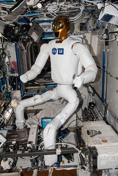
Robonaut 2 (Image from NASA)
Robonaut 2 (R2) is a humanoid that is helping astronauts with various tasks on the International Space Station (ISS). It is able to grasp objects, flip switches, and even to give a high-five to ISS crew members after successfully performing tasks.
R2 was originally designed and developed by NASA, in conjunction with General Motors, with assistance from Oceaneering Space Systems engineers to accelerate the development of the next generation of robots and related technologies for use in the automotive and aerospace industries.
NASA is using Robonaut as a test-bed to develop future robotics technology for space outposts on the moon and eventually on Mars.
In 2018, R2 had been on the ISS since February 2011. All was well until NASA attempted to install a pair of legs in 2014, on the torso-only robot, which ended in an intermittent power problem that plagued its operation on the ISS.
Once R2 returned to Earth, the problem was diagnosed and solved. NASA found that R2 was missing a ground path, so the computer chassis [in its stomach area] did not have the correct path to return its current; the electronics was finding sneak ground paths. The sneak path ultimately caused more damage than engineers had expected, so it took eight months to correct it.
Now, the certification unit needed to be made identical to the flight unit. NASA then decided to go through and assess and mitigate some other problem areas. This was not a complete redesign but there was a relatively large amount of electrical reworking. The same printed circuit boards remained in place, performing the same original functions. The major change was moving some power component locations around.
R2’s legs are key to all of NASA’s research objectives once it returns to the ISS. Since the NASA Gateway has become a program, with a planned space station in orbit around the moon, one of the key systems on board Gateway is going to be intravehicular robots. They’re not going to exactly look like R2, but they will have some of the same functionality. These robots will be mobile, able to carry payloads from one part of the module to another, doing some dexterous manipulation tasks, inspecting behind panels, and more. The legs are a key to being able to push the readiness level of some of the pieces of technology NASA has been demonstrating on the ground for the past three to five years.
![]()
R2 on the ISS with new legs (Image from NASA)
R2 will be mobile! On the ISS, there are a series of blue handrails that the crew uses to either stick their feet under to stay stationary, or to move through the labs. R2’s feet will grip those, and NASA has been working to have R2 put together multiple steps. Theoretically R2 should be capable of doing what it could do on the ground, which is, take two or three steps completely unassisted. R2 will only be in one lab on the ISS, since it will have a [power and communications] tether, but NASA says that it will be able to show quite a bit of good performance.
![]()
R2 strength (Image from NASA)
R2 is a state-of-the-art, highly dexterous anthropomorphic robot. R2 is capable of handling a wide range of Extravehicular Activity (EVA) tools and interfaces; however, R2 is a significant advancement over its predecessor R1. R2 is capable of speeds more than four times faster than R1, is more compact,...
Read more -
California’s burning fires monitored by NOAA/NASA’s Suomi NPP Satellite
09/11/2020 at 23:29 • 0 comments![]()
Image from NASA
Human health and welfare depends partly on our ability to understand and adapt to environmental changes; severe forest fires like those occurring in California today are a stark example. Viewing these fires from space are a great help to understanding and fighting the fires.
NOAA/NASA's Suomi NPP satellite observes the Earth’s surface twice every 24-hour day, once in daylight and once at night. In its orbit NPP flies 512 miles (824 kilometers) above the surface in a polar orbit, and circles the planet roughly 14 times a day. NPP sends its data once each orbit to the ground station in Svalbard, Norway as well as continuously to local direct broadcast users.
A stunning 3.1 million acres have burned this year in California alone (per CAL fire); this is up from a total of 2.5 million acres as of Wednesday, September 09, 2020. In addition, 805,314 acres have been lost in Oregon (State of Oregon Fires and Hotspots Dashboard, as of 9:30am EDT Sep. 11) and 500,000 acres (Northwest Interagency Coordination Center) in the state of Washington. Winds blowing through the west have been stoking fires and aiding the quick spread as can be seen in the growth of over a half million acres in less than two days. There have been 12 wildfire-related fatalities this year. Records have been shattered during this fire season and experts continue to blame drought, excessive heat and strong winds for this terrible life-threatening situation.
Earth’s climate continues to change and many scientists believe that these types of fire events will not only continue but will worsen. A predictive meteorologist for the National Interagency Fire Center, Nick Nausler sent this out on Twitter: "Multiple fires made 20-plus mile runs in 24 hours over the last few days in California, Oregon and Washington. Such distances traveled so quickly may not be all that rare in grassland fires. However, most of these fires are making massive runs in timber and burning tens of thousands of acres and in some cases 100,000-plus acres in one day. The sheer amount of fire on the landscape is surreal."
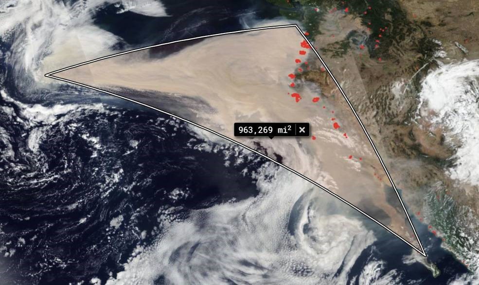
![]()
California’s fire seen from space: The square miles of smoke in the image below totals 963,269. That estimate has been computed using the measurement within the NASA Worldview application tool (Image from NASA Worldview)
NOAA/NASA's Suomi NPP satellite captured a series of images (made into an animated GIF) showing the winds changing direction on Sep. 06, 2020 when choking clouds of brown smoke began to billow and cascade into the Pacific Ocean. By September 10, these clouds of smoke had traveled over 1,300 miles.
Suomi NPP — the National Polar-orbiting partnership between NASA, the National Oceanic and Atmospheric Administration, and the Department of Defense -- is the first of a new generation of satellites that will observe many facets of our changing Earth, the satellite collects critical data to improve scientists’ understanding of long-term climate change and short-term weather conditions. With this satellite, NASA continues many important data records initiated by the agency's Earth Observing System satellites, monitoring changes occurring in the atmosphere, oceans, vegetation, ice and solid Earth. NASA's Earth Observing System Data and Information System (EOSDIS) Worldview application provides the ability to interactively browse over 700 global, full-resolution...
Read more -
NASA Ion Propulsion rocket engines
08/22/2020 at 22:30 • 0 comments![]()
NASA’s Dawn spacecraft with its Ion Propulsion engine (Image from NASA JPL)
This article is not about Dilithium crystal-powered engines boosting rockets to multiple Warp speeds, but I will introduce you to the realities of NASA’s Ion Propulsion rocket engine efforts. This is advanced rocket science at its best with NASA’s next generation Ion Propulsion Engine technology research.
The first spacecraft using an ion propulsion engine was Deep Space 1, that did a fly by of asteroid 9969 Braille and the comet Borrelly. The fuel used by Deep Space 1 was Xenon. The Dawn spacecraft followed this successful effort.
NASA’s Dawn spacecraft orbited Vesta, a protoplanet, on July 15, 2011. This was the first probe ever entering the large asteroid belt between planets Mars and Jupiter. The spacecraft used its ion propulsion engines to travel as low as 130 miles searching for moons. The mission was a success and ended on November 1, 2018.
Dawn’s ion propulsion system enabled it to be the first spacecraft with the ability to orbit two extraterrestrial destinations---Vesta and Ceres.
The method of Ion Propulsion
Ion engines rely on two principles, which Isaac Newton first described in 1687, that led to the development of Ion Propulsion. That first ion propulsion principle led to the Ion engine design idea of a positively charged atom (ion) being pushed out of the engine at a high velocity. Newton’s Third Law of Motion states that for every action there is an equal and opposite reaction, this enables a small force pushing back on the spacecraft in the opposite direction – to move forward!
According to Newton’s Second Law of Motion, there is a relationship between the force (F) exerted on an object, its mass (m) and its acceleration (a). The well-known F=ma equation describes that relationship, and says that the small force applied to the spacecraft by the exiting atoms provide a small amount of acceleration to the spacecraft. If we can push enough atoms out, we will be able to get enough acceleration to speed the spacecraft up.
A spacecraft powered by ion engines is able to attain speeds of up to 90,000 meters per second (more than 201,000 mph!)
As for fuel efficiency, ion engines are able reach more than 90% fuel efficiency, while chemical rockets are only able to attain 35% percent efficiencies.
Ion engine thrusters are fueled via inert gases. Most ion engines use Xenon, a non-toxic, chemically-inert (meaning no risk of exploding), odorless, tasteless and colorless gas.
Ion propulsion could be used to boost the International Space Station or even NASA’s Gateway into higher orbits and will most likely be a part of many future missions exploring our solar system and beyond.
Meeting a rocket scientist
During a behind-the-scenes visit to NASA’s Jet Propulsion Labs (JPL), founded and run by California Institute of Technology (Caltech) in Pasadena, CA, I met a NASA chief engineer John Brophy. Figure 1.
![]()
Figure 1 John Brophy, Chief Engineer for the Asteroid Re-direct Mission (Image from Loretta Taranovich)
Brophy discussed the Solar Electric Propulsion (SEP) program which is the development of the next-gen Ion Propulsion engine. This effort will enable a high thrust-to-power ability for the ion engine.
I was able to get a peek inside the large vacuum chamber, simulating the cold void of space, while the new ion engine was firing with a blue/white plasma emanating out of the back of the engine. Figure 2.
![]()
Figure 2 Looking through the small, thick glass portal to the vacuum chamber. The Ion engine can be seen with its circular plasma glowing white and ions emanating from the center of the engine towards the left side of the chamber. (Image from Loretta Taranovich)
Presently, NASA Ion thrusters are powering over 100 geosynchronous satellites, orbiting the Earth, keeping them in their desired locations. There were also three NSTAR ion thrusters...
Read more -
NASA Gateway
08/07/2020 at 21:05 • 0 comments![]()
SpaceX Dragon XL simulation of the journey to the Gateway (Image from SpaceX)
The final manned Moon landing and expedition, by Apollo 17, lasted from December 7-19, 1972. Lunar Module Pilot, Harrison Schmitt was a member of the three man crew; see this hackaday article
“The last men on the Moon: Helium 3”
We now embark upon a journey with NASA’s Artemis program (See “NASA: From the Moon to Mars”) along with NASA’s “Gateway” program, a very important aspect of deep space exploration that will land the first woman and the next man on the Moon by 2024. The Space Launch System (SLS), the most powerful rocket ever built, and the Orion program are also key elements in this plan to travel where no human has ever traveled before.
SpaceX has the first Gateway Logistics Services contract to deliver supplies to the first lunar outpost. The SpaceX Dragon XL is a key component here; astronaut pilot Victor Glover and crew will fly the second mission later in 2020.
![]()
NASA Gateway has power and propulsion, a habitation and logistic component, and logistic supply capabilities (Image from NASA)
The Gateway is essentially a planned outpost that will orbit the Moon and provide critical support for astronauts’ sustainable and long-term return to the surface of the Moon. NASA will be able to have new efforts on, as well as orbiting, the Moon that will prepare NASA to ultimately send astronauts on a long journey to explore Mars as we explored the Moon in the late 60s and early 70s.
The Gateway is planned to be a port for deep space travel for spacecraft traveling far beyond the Moon and Mars as well.
There is a Gateway Power and Propulsion Element (PPE), a Habitation and Logistics Outpost (HALO), and logistics needed for Earth explorers to fly beyond Earth’s confines into places where humans only dreamed about----until now!
Power and Propulsion Element (PPE)
The PPE is composed of a high power, 60kW solar electric propulsion spacecraft which will power high-rate communications equipment, attitude control systems, and orbital transfer missions. Maxar Technologies will develop, build and support the PPE. Maxar also developed the robotic arm for the Perseverance Rover just launched towards Mars in July 2020.
![]()
Deep Space Gateway PPE showing the concepts for solar arrays (Image from NASA)
Habitation and Logistics Outpost (HALO)
HALO is the crew cabin that astronauts will utilize upon their arrival, on the Orion spacecraft, to the Gateway. HALO provides life support to the astronauts as they prepare for their departure to the lunar surface. HALO will also provide control and data handling, energy storage and power distribution, thermal control, communications and tracking capabilities, and environmental control/life support for the Orion spacecraft and its crew. HALO also has docking ports for other future visiting vehicles and storage space for science.
As for the logistics, for astronauts getting ready to travel to the surface of the Moon from Gateway, deliveries of critical, pressurized as well as unpressurized cargo, science experiments and supplies will be brought up from Earth by SpaceX. Commercial Lunar landers will deliver NASA-provided payloads for performing unmanned science investigations as well as demonstrate advanced technologies on the lunar surface, thus paving the way for NASA astronauts from Gateway to land on the lunar surface by 2024.
-
NASA Atomic Oxygen method: Decontamination of COVID-19
07/19/2020 at 23:34 • 0 comments![]()
Shown here is Atomic Oxygen (O) created in a lab by separating Oxygen (O2), which occurs naturally in Earth’s atmosphere, into O, known as Atomic Oxygen (containing only one atom of Oxygen) (Image from NASA)
NASA Glenn Research Center has embarked upon an effort to decontaminate personal protective equipment (PPE), for health personnel, in the war on COVID-19.
Atomic Oxygen
The method of using Atomic oxygen, an elemental form of oxygen that does not exist in Earth's atmosphere, is at the heart of NASA’s COVID-19 research efforts. This all began, years ago, when NASA performed extensive research into the damage to satellites caused by atomic oxygen in low Earth orbit, which had also led to a new way to restore damaged artwork.
NASA has a team of researchers who were able to use this method to benefit the health workers, the public, or nation and the world. Atomic oxygen decontamination is a viable method presently being evaluated for decontamination. The Food and Drug Administration (FDA) has been reviewing another method as well, peracetic acid, which has proven to work for five cycles of decontamination. The FDA is reviewing this method for emergency use authorization. Figure 1.
![]()
Figure 1 N95 masks are shown here being disinfected in a decontamination room, at University Hospitals (UH), using the peracetic acid method (Image from University Hospitals on NASA’s website)
Prevalent in low-Earth orbit, these single oxygen atoms can remove organic materials that can’t easily be cleaned by other methods. On Earth, NASA creates atomic oxygen by adding ozone (O3) in a chamber and heating it. The ozone will then decompose into atomic oxygen (O); it can then kill organisms such as viruses. Ozone diffuses very well through and around objects; this makes it promising for sterilizing inside an N95 mask filter or loosely stacked masks, and may possibly sterilize without leaving any residue. The process can be scaled up to treat multiple batches of PPE or can be made portable for small hospitals in rural areas. No liquid chemicals are needed, only oxygen and nitrogen gas.
Glenn research engineers, along with physicists from the Science Applications International Corp (SAIC), have now developed a process and hardware to decontaminate medical masks using atomic oxygen. Testing is ongoing to ensure that multiple decontamination cycles will not damage the PPE.
An independent lab has also recently performed filtration tests which have demonstrated that N95 masks had filtered well and passed acceptance testing after 20 minutes of atomic oxygen treatment. In early May, NASA provided a prototype for UH to test on N95 masks. Early results confirm that the method deactivates the virus; continued testing will determine the minimum ozone concentration and exposure time needed for disinfection.
Peracetic Acid
Peracetic acid is a chemical disinfectant typically used in the health care, food, and water treatment industries and is one other option for decontaminating PPE. This disinfecting method will kill 99.9999% of viruses as well as highly resistant bacterial spores from contaminated N95 masks with no detectable loss of filtration, structural integrity, or strap elasticity for up to five decontamination cycles. The Department of Medicine at UH Cleveland Medical Center believes that the peracetic acid disinfection method is the quickest method for mass-decontamination of N95 respirators presently available.
Stay tuned for more on this research study which will bring space research to Earth in order to help stem the Corona virus and protect our brave healthcare provider heroes.
-
NASA Launch Control: The Apollo Program leading to the Artemis Program
07/03/2020 at 19:14 • 0 comments![]()
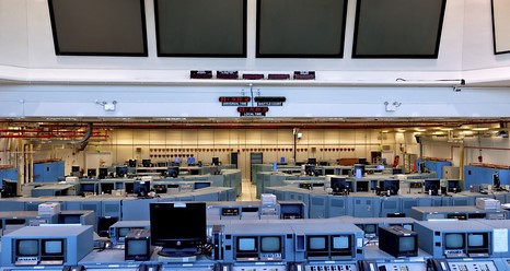
Present day Firing Room at Kennedy Space Center (Image courtesy of NASA)
NASA’s Launch Control Center (LCC) has been the hub of launch operations at Kennedy Space Center (KSC) in Florida since the days of the 1960s Apollo program.
This four-story building is located at the southeast corner of the huge Vehicle Assembly Building in the Launch Complex 39 area, only a few miles from Launch Complexes 39A (Space-X launches from here) and 39B ( NASA Mars Orion/SLS will launch from here as well.
I was up on the third floor where there are four multi-level firing rooms in which the final checkout of each launch vehicle, that would carry astronauts, was conducted. At the point that the vehicle receives a ‘go’ for launch, the firing room teams became responsible for the control and supervision of the vehicle and liftoff until it cleared the launch pad towers. At that point, all operations were handed over to Johnson Space Center in Houston which housed the Mission Control teams.
![]()
Launch Director (only in his imagination), Steve Taranovich, announces ”We are go for launch—-T-minus 30 seconds and counting…29….28….27….”. This is the actual LCC Launch Director desk for the Apollo launches in the 1960s to early 1970s. (Image courtesy of Loretta Taranovich)
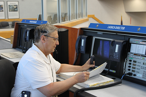
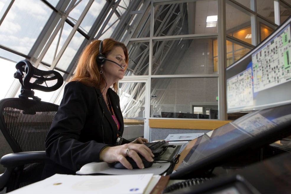
Launch Director, Charlie Blackwell-Thompson, is NASA's first female launch director. She will lead the countdown when the Artemis mission propels the next American astronauts to the moon – including the first woman.
![]()
Here is a real Launch Director, Charlie Blackwell-Thompson, working at her console in Firing Room 1 at KSC. All activities at the launch pads can be run from a firing room (Image courtesy of NASA)
![]()
This is the view I had, of Launch Complex 39B, while looking out one of the view windows on a third floor firing room in the LCC. The LCC is a reinforced concrete building designed in that way to provide optimal acoustics from the massive launch sound and vibration from Launch Complex Pad 39B. The massive, double-paned windows, of which I am looking out, are made of a special shock- and heat-resistant glass that extends across the full width of the East wall of the four firing rooms with an amazing view of launch pad 39B. (Image courtesy of Loretta Taranovich)
The LCC was originally constructed for checkout and launch functions of the Apollo program. When Apollo ended, the LCC was updated for duty to provide the checkout and launch functions for every Space Shuttle mission until the last one on July 8, 2011.
![]()
The present day LCC ready for 21st century launches (Image courtesy of NASA)
Firing Room 1 (FR1), in the LCC, called the Young-Crippen Firing Room, has been completely renovated and functioned as NASA's firing room for launches of the Space Launch System (SLS) and will also serve the Orion spacecraft on exploration missions. This room was dedicated in honor of the crew of mission STS-1, Commander John Young and Pilot Robert Crippen. These two astronaut test pilots were launched on the first shuttle mission on April 12, 1981, aboard Space Shuttle Columbia from firing room 1 at KSC.
This NASA Launch Control Complex will be handling the upcoming Artemis Moon launches and Orion program. Stand by for more on these historic scientific and engineering exploration adventures here on hackaday.io
-
The last men on the Moon: Helium 3
06/21/2020 at 22:25 • 0 comments![]()
Apollo 17 astronaut Harrison Schmitt (left) and Steve Taranovich (right) during a meeting we had at the Long Island Cradle of Aviation. (Image from Loretta Taranovich)
Apollo 17 carried the last astronauts to the Moon on December 10, 1972 (I had just graduated with a Bachelor’s in Electrical Engineering degree that May from New York University School of Engineering & Science). The Crew consisted of:
Eugene A. Cernan, Commander Harrison H. Schmitt, Lunar Module Pilot Ronald E. Evans, Command Module Pilot
The lunar landing site chosen for this last mission was the Taurus-Littrow highlands and valley area. That site was picked as a location because that was where both older and younger rocks than those previously returned from the other Apollo missions. Scientific objectives of the Apollo 17 mission included, geological surveying and sampling of materials and surface features.
It was no coincidence that they had an astronaut on board who had a Ph.D. in Geology----Dr. Harrison H. Schmitt. One of the key elements he found in the Lunar Regolith was Helium-3. Dr. Schmitt told me that if we could fill an area the size of the old Space Shuttle bay with Helium-3, bring it back to Earth, and use it in a Fusion Reactor, we could power the United States for a year. As a plus, the by product of Fusion is NOT radioactive! Only one metric Tonne (2200 pounds) of Helium-3 fused with Deuterium, a heavy isotope of Hydrogen, will have enough energy to supply a city of ten million with a year’s worth of electricity! Proposed fusion reactors generally use hydrogen isotopes such as deuterium and tritium, which react more easily than hydrogen to allow them to reach the Lawson criterion requirements with less extreme conditions.
There is a great deal of excellent information on Helium-3 and many other experiences as to why we need to get back to the Moon, in Schmitt’s book entitled, “Return to the Moon”---it’s a real page-turner!
Mining the Moon will be a key effort for success, see my hackaday.io article “NASA: From the Moon to Mars” and a NASA JPL discussion on How Moon mining could work. NASA’s Artemis program discusses returning to the Moon on their site. NASA also has an excellent article on Harnessing power from the Moon.
![]()
Here is how Astronaut Harrison Schmitt signed my copy of his book “Return to the Moon“ (Image from Loretta Taranovich)
One of the stumbling blocks for using Helium-3 in a Fusion reactor is that we have no fusion reactors except in university and research stages. Naysayers claim that this will never happen. Well, people said that man could never fly, or how can we ever get to the Moon? That’s impossible!
Well, it will probably be well into the late 2020/early 2030 timeframe before we will be looking at mining Helium-3. A company named Fusion Reactors is saying that they can develop a fusion reactor that could deliver energy to the grid by the end of 2032. With NASA and the US government help, this can be a reality. Then there is ITER, a 35 nation collaboration effort to build a fusion reactor.
Fusion power is a proposed form of power generation that would generate electricity by using heat from nuclear fusion reactions. In a fusion process, two lighter atomic nuclei combine to form a heavier nucleus, while releasing energy. Devices designed to harness this energy are known as fusion reactors.
As a source of power, nuclear fusion is expected to have several advantages over fission. These include reduced or no radioactivity in operation and little or no high-level nuclear waste, ample fuel supplies, and increased safety.
Check out this Facebook Fusion Reactors site and the World Nuclear Association. There is also a good article on bigthink.com
-
NASA Vehicle Assembly Building (VAB)
06/13/2020 at 22:01 • 0 comments![]()
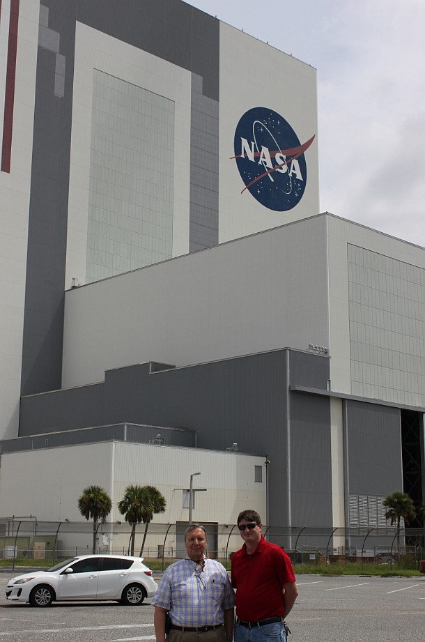
Author Steve Taranovich (left) and my NASA guide Matthew Miller (right) in front of NASA’s Vehicle Assembly Building (VAB), the only building to assemble a rocket that carried humans to the surface of another world. (Image courtesy of Loretta Taranovich)
I visited NASA Kennedy Space Center (KSC) in Florida, behind the scenes, and while I was there I had the pleasure of visiting the massive Vehicle Assembly Building whose sole purpose is to assemble rockets and payloads for their missions. This building is especially busy nowadays since commercial spaceflight has made Kennedy Space Center a Spaceport. This means KSC is no longer solely for NASA use but also accommodates Space-X, Blue Origin, Boeing, and more commercial efforts to come.
The VAB serves as the central hub of NASA’s multi-user spaceport, which is able to host several different kinds of rockets and spacecraft at the same time, both manned and unmanned. Some of these rockets and spacecraft will launch payloads into Earth orbit and many will be sent, first unmanned and later manned, to the Moon, Mars, and into deep space. The VAB has the infrastructure to prepare these varied missions for their exciting journeys.
![]()
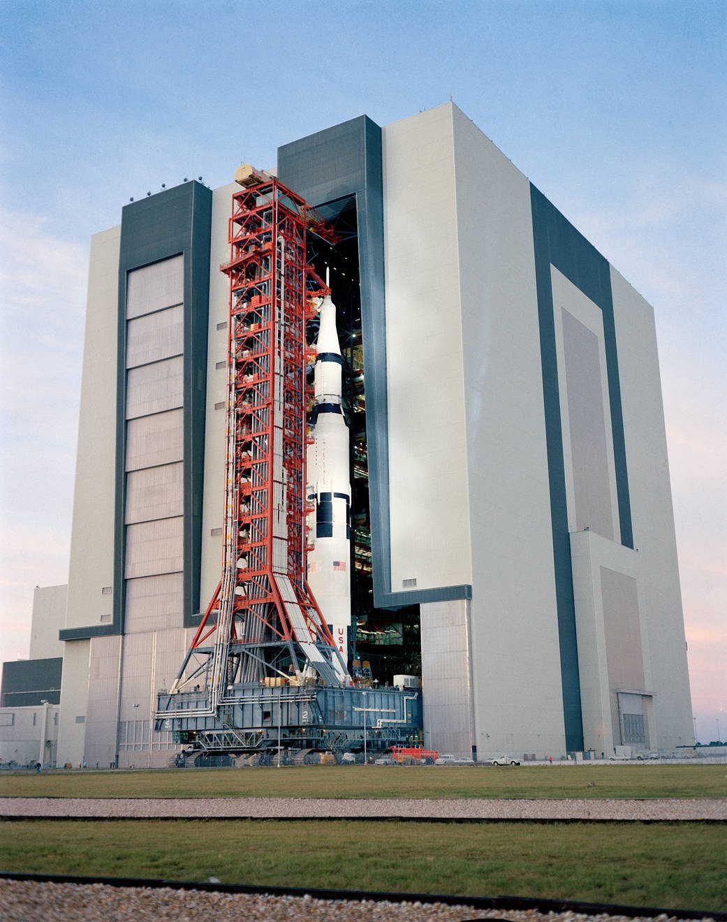
This photo was taken on November 9, 1970, with a ground level view at Launch Complex 39, Kennedy Space Center, with the Apollo 14 (Spacecraft 110/Lunar Module 8/Saturn 509) space vehicle exiting the Vehicle Assembly Building. The Saturn V stack and its mobile launch tower, atop a huge crawler-transporter, were being rolled out to Pad A. (Image courtesy of NASA)
The VAB construction began with machines driving the first steel pilings into the ground, as part of the foundation, on Aug. 2, 1963. This effort was during NASA's early days focused upon sending astronauts to the moon for the Apollo Program by the end of the 60s decade. In total, 4,225 pilings were driven down 164 feet into bedrock with a foundation consisting of 30,000 cubic yards of concrete. Construction of the VAB took 98,590 tons of steel. The building was completed in 1965, and was one of the largest buildings in the world with 129,428,000 cubic feet of interior volume. The structure covers eight acres, soars 525 feet tall and is 518 feet wide. To accommodate moving, processing and stacking rocket stages, 71 cranes and hoists, including two 250-ton bridge cranes were installed.
On the east and west sides of the building there are four high bay doors, each was designed to open 456 feet in height to allow the rollout of the Apollo/Saturn V moon rockets mounted atop launch umbilical towers. These doors are the largest in the world and take about 45 minutes to completely open or close.
NASA had an American flag painted onto the VAB in 1976 for the Bicentennial Exposition on Space and Technology.
![]()
Shown here is the largest American flag, a 209-foot-tall, 110-foot-wide star spangled banner which is painted on the left side of the VAB (Image courtesy of NASA/Bill White)
The Exploration Ground Systems Program is leading an extensive refurbishment of the VAB to prepare it for the next chapter in human exploration. The modernization calls for a flexible setting rather than configuring the whole building toward supporting one design.
Old communications, power and vehicle access resources are being replaced with modern, efficient systems. Some of the utilities and systems scheduled for replacement have been used since the VAB opened in 1965. Apollo-era water, sewer and drainage piping is being replaced, and installation of a new fire protection system is just about complete.
![]()
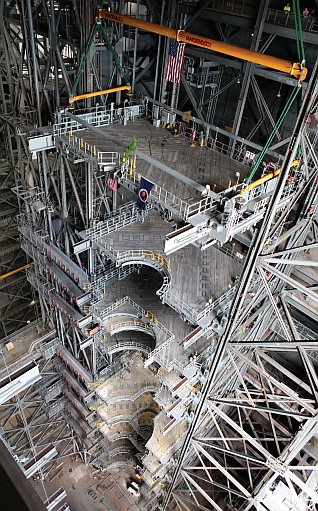
Up towards the top interior of the VAB, a crane is shown here lowering the final work platform, ‘A north’, for installation in High Bay 3 on Jan. 12, 2017. In view below platform ‘A’, are nine previously installed levels of platforms. They will surround NASA’s Space Launch System (SLS) rocket and the Orion spacecraft to enable access during processing for missions, including the first uncrewed flight test of Orion atop the SLS...
Read more -
Mars 2020 Perseverance: Drone helicopter in a CO2 atmosphere
06/06/2020 at 23:10 • 0 comments![]()
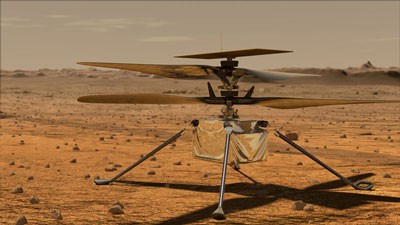
(Image from NASA)
Leonardo Da Vinci once said, “When once you have tasted flight, you will forever walk the earth with your eyes turned skyward, for there you have been, and there you will always long to return.”
![]()
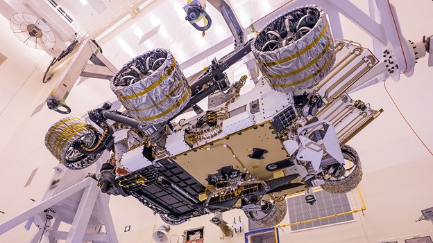
The Mars 2020 Rover Perseverance with its helicopter, Ingenuity, cocooned in the lower center of the Rover getting ready to launch in July 2020 (Image from NASA-JPL-Caltech)
In my previous article on hackaday.io, entitled Mars 2020 Rover: Perseverance, I outlined the instrumentation on the Mars 2020 Rover. In this article I will highlight the Mars helicopter. Meet Ingenuity, a four pound helicopter drone with four foot diameter, twin counter-rotating, propellers.
The name ‘Ingenuity’ was submitted by an Alabama 11th grader Vaneeza Rupani, as part of NASA's "Name the Rover" contest for Mars 2020.
After landing on Mars, at the time Ingenuity is ready to fly, Perseverance will move 100 meters on the Mars surface and will perform a systems check on the helicopter. After this, the helicopter will have an initial flight test for as much as 30 days. The Mars atmosphere is very thin: less than 1% the density of the Earth’s. Once the helicopter is detached from the Rover, it will use its own solar panel, situated above its propellers, to generate its electrical power independent of the Rover. Figure 1.
![]()
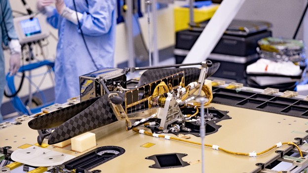
Figure 1 The Mars Helicopter Ingenuity is shown here, in the assembly area at Kennedy Space Center, mounted to the bottom of the Rover (Image from NASA)
Why a drone helicopter?
Ingenuity flies pretty independently, without human control. It will take off, fly, and land with minimal commands from Earth sent in advance.
Because of the absence of global positioning systems for Mars, dead-reckoning methods like Wheel Odometry (WO) and Visual Odometry (VO) are the major sources of localization on Mars for the Rover.
Ingenuity has the ability to fly and explore larger Mars surface areas with down-facing cameras which will provide high resolution data to assist the Rover to identify small hazards like steps and pointy rocks.
Ingenuity is much faster than the Rover; however, its operation time is limited to only one 90-second flight per day due to the severe power constraints. The helicopter can fly up to 90 seconds after it takes off from the Rover’s body, to distances of about 980 feet (300 meters) at a time, and about 10 to 15 feet above the Mars surface. An on-board solar panel charges Lithium-ion batteries which in turn will provide Ingenuity with 350W of average power energy during flight.
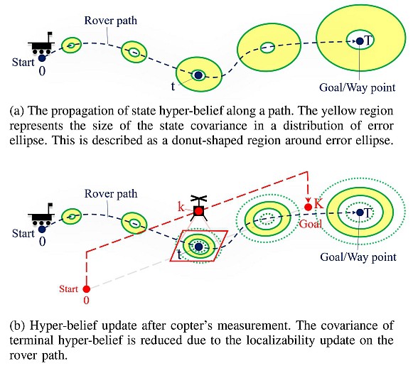
The mission concept has the copter as a scout to collect data before the beginning of Perseverance’s traverse on each Martian day. The Rover will plan an optimal path that avoids critical terrain hazards and regions with low localizability using the updated map information provided by Ingenuity.
The localizability map is first initialized with satellite measurements, and then dynamically updated by Ingenuity. Figure 2.
![]()
Figure 2 A hyper-belief propagation in the Rover’s state estimation (Image from Reference 1)
Ingenuity’s observation has higher resolution and fidelity than satellites, but the scope is smaller than the entire map.
Rover safety
Ingenuity adheres to the safety of the Rover by constantly keeping a certain, pre-determined distance from the Rover.
Challenges of a drone helicopter on Mars
The main challenge of a powered flight on Mars is the generation of lift in the very thin Mars atmosphere. At the surface level of Mars, the average air pressure is just 6 mbar, that is, 0.6% of the air pressure at sea level on Earth. A very high copter rotor speed between 2,300 and 2,800 r/min is needed. This is five to 10 times faster than the rotor speed of an average helicopter in Earth’s atmosphere. The mass of Ingenuity is limited to 1.8 kg to meet mission requirements. Lightweight foam-filled, 1.1-m-in-length carbon fiber rotors are used to generate the required lift while minimizing weight....
Read more -
Mars 2020 Rover: Perseverance
06/01/2020 at 19:37 • 0 comments![]()
NASA and Space-X just successfully launched the Crew Dragon space capsule to the International Space Station (ISS). SpaceX’s Dragon also marks the first time a commercial aerospace company has carried humans into Earth's orbit. NASA astronauts Bob Behnken and Doug Hurley were on this first manned launch from US soil in nine years! Congratulations to all involved!
Next, we are looking forward to the launch of the Mars 2020 Rover to Mars.
![]()
At NASA’s JPL facility, I had the pleasure of meeting Soren N. Madsen, Mars 2020 Payload System Manager and Ann Devereaux, Lead Flight System Engineer at NASA JPL/Caltech. In this photo they are standing in front of a Mars 2020 Rover model. They are two key members of an extremely talented team of engineers and scientists that are ultimately paving the way to a manned mission on Mars. (Image courtesy of Loretta Taranovich)
The Perseverance Rover is scheduled to launch sometime between July 17, 2020 and August 5, 2020. The first launch opportunity will be on July 17, 2020 at 9 AM EDT.
![]()
I stood in front of the Mars Curiosity Rover, the one presently roaming Mars, in the Mars Yard at NASA Jet Propulsion Lab (JPL) at Caltech in Pasadena, CA. The Rover is about the size of a Humvee with an offset ‘head’ atop a mast whose ‘eye’ is the Mastcam-Z (Image courtesy of Loretta Taranovich)
Mars 2020 Rover Perseverance
![]()
Here, at Cape Canaveral Air Force Station, Florida, we see the Crawler moving towards Launch Complex 41 at 1 mph. The Perseverance Rover sits in an enclosure atop an Atlas V-541 rocket. (Image courtesy of NASA)
See the simulation for Entry, descent, and landing on Mars on NASA’s website.
Perseverance instrumentation
![]()
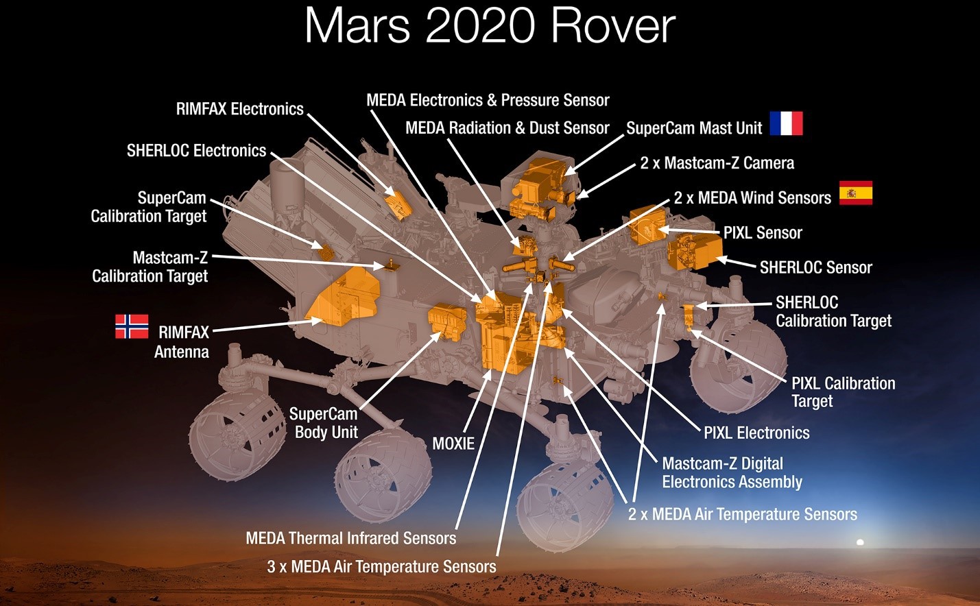
The Mars 2020 Rover Perseverance is chock full of science instruments that will examine the geology on Mars as well as acquire information on atmosphere, environmental conditions, and possible biosignatures! (Image courtesy of NASA)
NASA has announced the actual final payload of science instruments as seen above. Here are some details about each device:
The Mastcam-Z: The Rover’s eyes
I am proud to say that James Bell was the principal investigator for this device. Bell is from the Arizona State University, Tempe, AZ right across town from where I live.
The Mastcam-Z (The ‘Z’ is for Zoom) is a mast-mounted camera system equipped with a zoom function mounted on the ‘head’ of the Rover. Mastcam-Z cameras can zoom in, focus, and take 3D pictures and video at high speed for detailed examination of distant objects. This device helps determine which rocks might preserve signs of past life and signs of existing water or ancient water features. It can see a house-fly at a distance of the length of a soccer field!
Mars Environmental Dynamics Analyzer (MEDA)
![]()
MEDA has sensors located on the Rover’s mast ‘neck’ and on the deck, front and interior of the Rover’s body seen circled in yellow in this image. (Image courtesy of NASA/JPL-Caltech)
This device was developed by Jose A. Rodriguez Manfredi, Principal investigator, Centro de Astrobiologia, Instituto Nacional de Tecnica Aeroespacial, Madrid, Spain, and makes weather measurements of wind speed and direction, temperature and humidity, and also measures the amount and size of dust particles in the Martian atmosphere. The device can also help predict weather, measure radiation and water vapor.
Here is an instrument which is my favorite on the Rover:
Mars Oxygen ISRU [In-Situ Resource Utilization] Experiment (MOXIE)
![]()
MOXIE will produce Oxygen from the Martian atmospheric Carbon Dioxide (Image courtesy of NASA/JPL-Caltech)
Michael Hecht is the Principal Investigator from the Massachusetts Institute of Technology, Cambridge, Massachusetts. He says, "When we send humans to Mars, we will want them to return safely, and to do that they need a rocket to lift off the planet. Liquid oxygen propellant is something we could make there and not have to bring with us. One idea would be to bring...
Read more -
The ‘Behemoth’: NASA’s 6.6 million pound Crawler/transporter
05/23/2020 at 21:49 • 0 comments![]()
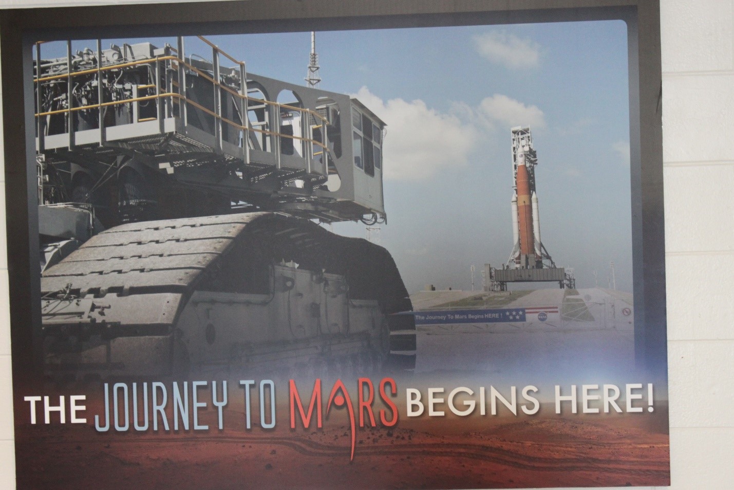
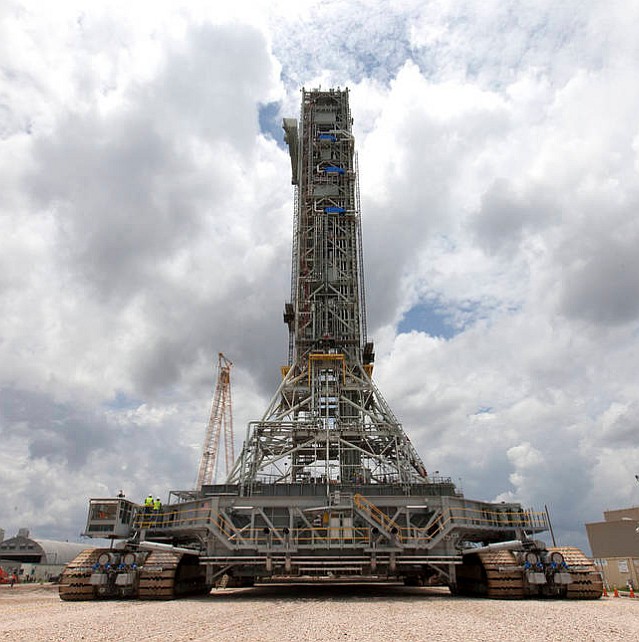
Figure 1 The Mars Orion Spacecraft will be perched atop the mighty Space Launch System (SLS) that will travel from NASA’s Vehicle Assembly Building to Launch Complex 39B via a massive Crawler-Transporter 2 moving at the speed of a sloth---one mile per hour. Artemis I will be the first launch towards our goal to land astronauts on Mars. (Image at NASA Kennedy Space Center [KSC] courtesy of Loretta Taranovich)
![]()
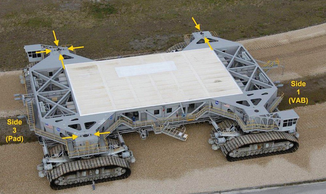
Figure 2 The crawler-transporter 2 has four pickup points (shown in yellow) that will be used to lift the mobile launcher (See Figure 3) with NASA’s SLS and the Orion spacecraft on top of the Crawler for its eight hour trip to Launch Complex 39B (Image courtesy of NASA)
The Crawler is 131 feet long and 113 feet wide.
![]()
Figure 3 The Mobile Launcher shown here sitting atop the Crawler-transporter 2. The vehicle’s Control Room cab can be seen on the left side just above the treads. (Image courtesy of NASA)
Some crawler history
There were two of these behemoth machines, called crawler-transporters, that have carried rockets and spacecraft to launch pads for more than 50 years at NASA’s Kennedy Space Center (KSC) in Florida. Each of these crawlers span the size of a baseball infield diamond and are powered by locomotive and large electrical power generator engines.
These crawlers were built in 1965 to move the massive Saturn V rocket, which carried the Apollo Moon spacecraft, from Kennedy Space Center’s Vehicle Assembly Building (VAB) to Launch Complex 39. After the Moon landings and Skylab programs ended, the crawlers continued to take the many space shuttles to their launch pads for the next 30 years.
After the shuttle fleet retired in 2011, the crawlers became critical elements of future launch operations at Kennedy. Crawler-Transporter 2 will be integral to the Artemis program, sending the first woman and the next man to the Moon
Crawler Facts from NASA
Weight: Approximately 6.6 million pounds (or the weight of about 15 Statues of Liberty or 1,000 pickup trucks).
Height: Varies from approximately 20 feet to 26 feet, based on the position of the jacking, equalization and leveling cylinders.
Load Capacity: Able to transport 18 million pounds (or the weight of more than 20 fully loaded 777 jet aircraft).
Aug. 26, 1967 – The first Saturn V rocket was moved to the launch pad for the unmanned Apollo 4 mission.
May 1, 1979 – A crawler transported space shuttle Enterprise, with external tank and two inert solid rocket boosters, to Launch Pad A for a fit check.
Nov. 16, 2011 – Moved Space Launch System’s (SLS) mobile launcher from the park site beside the Vehicle Assembly Building (VAB) to Launch Pad 39B.
![]()
Figure 4 A crawler could potentially lift and move the St. Louis Gateway arch weighing more than 34 million pounds! (Image at NASA KSC courtesy of Loretta Taranovich)
The newly installed generators in the crawler can each produce 1500 kW of power---that’s enough to power 17 International Space Stations (ISS)
NASA tells us that Phase I Crawler modifications, for the Artemis program, were replacement of existing roller assemblies and bearings with redesigned, upgraded assemblies and bearings which have a greater load capacity. An expanded and uprated lubrication system was added to service the new assemblies. The jacking, equalization and leveling system cylinders and piping were all replaced with redesigned and upgraded versions implemented during Phase II modifications.
Twenty-year-service life extension modifications were made, according to NASA, including a complete upgrade and modernization of the vehicle’s control room, an expanded strain and temperature system, a new condition monitoring system, two new Cummins 1,500-kilowatt AC generators, redesigned and uprated parking and service brakes, control system modifications, ALCO diesel engine refurbishments, a complete reconditioning of all gear cases and gears, and a new...
Read more -
NASA: From the Moon to Mars
05/16/2020 at 22:55 • 0 comments![]()
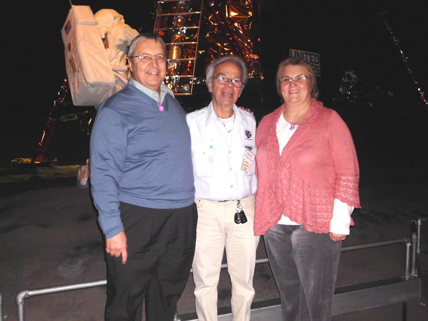
Left to right are Steve T (author), Ross Brocco (a 30+ year veteran Structural engineer for Grumman), and my wife and photographer Loretta. We are standing in front of an actual Grumman Lunar Module (LM) at the Cradle of Aviation Museum in NY circa 2012. This LM 13 was last in the series and never flew; its mission (Apollo 18) was cancelled to move on to the Space Shuttle program.
Ross Brocco is featured in my upcoming copyrighted book “Guardians of the Right Stuff”. He was at Grumman for 30+ years as a Structural Engineer on the Apollo Lunar Module program. Ross was responsible for the mechanical design of the front door hatch on the LEM and various other mechanical components.
![]()
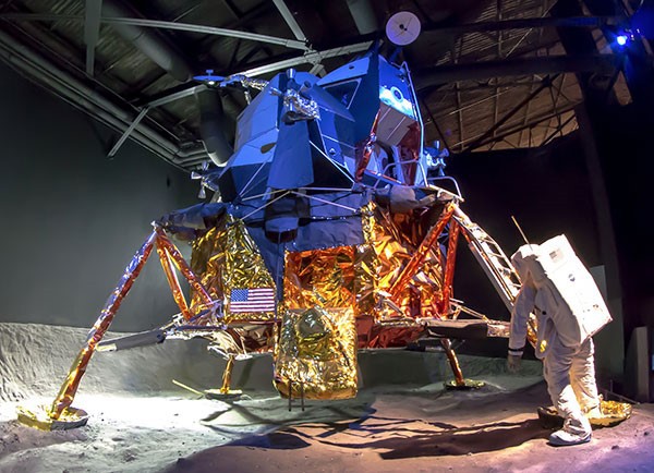
The Lunar Module was a true engineering marvel. Even to present day, it is the only crewed transport vehicle designed to function solely in the vacuum of space. It was expertly designed by Grumman Corp. on Long Island, NY. The LM's main purpose was to land men on the moon and return them safely to the Command Module orbiting the Moon. The LM was never actually flight tested because the Lunar environment could not be replicated. During the span of the Apollo program in the 60s and early 70s, 13 Lunar Modules were built by Grumman Aerospace Corporation (now the Northrop Grumman Corporation). Only six of those made manned lunar landings.
Fast forward to the present day efforts by NASA in their “Moon to Mars” program known as “Artemis” named after the sister of Apollo. This program will take astronauts back to the Moon.
On April 30, 2020 NASA chose Elon Musk’s SpaceX , Jeff Bezos’ Blue Origin, and a third party led by Dynetics of Huntsville, Ala. for initial design development work over the next 10 months for the next Lunar Landing system.
I met with former astronaut Lee Morin, MD, PhD. Dr. Morin explained the difficulty of bringing materials and supplies to the Moon to establish a base there which eventually will enable a Moon-to-Mars manned excursion instead of a direct Earth-to-Mars trip. The Rocket equation stands in our way!
![]()
M = Instantaneous Mass of the rocket, V = velocity, ISP*g = exhaust velocity
There is an excellent treatment of the Rocket Equation on Medium.com with “Rocket Science 101: The tyranny of the rocket equation”
The Apollo program only delivered a crewed payload of 6,900 kg to the surface of the Moon (It is a fact that in six Apollo Moon landings we only delivered a mass of about one fully-loaded van!). How are we to send such things as an earth-mover like a hydraulic excavator at 35,100 kg, or something like a habitat to work like US Lab Destiny at 14, 000 kg? The answer: convert resources already on the Moon for our needs of a crewed base there using Lunar Regolith, sunlight in a Vacuum with a three second delay in communications to Earth.
The best way to do this is “telepresence” or Robotic remote control in early missions with a payload of 1,000 kg to the Lunar surface. Probably a robotic rover that can dig and remove regolith and process it in a lab that needs to be built with an In Situ Resource Utilization (ISRU) Material Processing Lab on the Moon.
The ISRU Lab will ultimately be a place to assemble, manipulate, and repair apparatus. There will be a Solar Furnace to bake and fuse regolith (Regolith is not soil. Soil has organic content, and the moon's regolith has none. Volcanic soil is fertile, because of the nutrients in it). In this way Moon glass and ceramic materials can be made which will be 50x stronger than Earth glass.
Thin Film Deposition in the Lunar vacuum can create mirrored coatings on Moon glass-----this leads to solar cell manufacturing!
Extracting of metals like FeO and then using electrolysis in regolith melt can yield Oxygen.
![]()
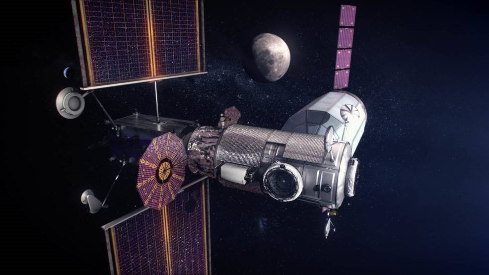
NASA's Phase 1 Gateway will include a Power and Propulsion Element, Habitation and Logistics Outpost and logistic supply that is a Lunar outpost orbiting...
Read more -
The Gerber Scale helped get us to the Moon
05/09/2020 at 23:54 • 0 comments![]()
Steve Taranovich examining an Apollo Service Module Engine at NASA White Sands. The Gerber Scale sped up designs like this to meet President Kennedy’s goal to get a man on the moon by the end of the 60’s decade (Image courtesy of Loretta Taranovich)
Back in the 60s, the Gerber Scale was quite a unique engineering instrument that enabled a new idea in the field of computation before computers came onto the scene. This was a manual and mechanical device that helped engineers immensely in that era.
The Gerber scale would perform computations directly on graphs and curves. The device was critical for reading, plotting, and interpolating on a graph in the days when plotter/paper graph printouts were popularly used.
During the birth of the space program at NASA, there were no computers of calculators available for engineers to simplify their calculations and charts/graphs. NASA engineers used the Gerber scale in the 60s for such things as pressure ratio from navigation, center of gravity, spacing rivets, laying out an airfoil section, and the power ratio of two curves, just to name a few.
Multiplication and division of a length by a number can be done as well as finding the peak of a curve. See the original Gerber Scale Application and Instruction Manual by Joseph Gerber, Chairman, Gerber Scientific for many more uses.
Ray Melton, an engineer who worked at NASA White Sands in the early days of the space program, used the Gerber Scale in his Rocket Engine-related work. Figure 1.
Figure 1 Ray Melton used this Gerber Scale for his work in the Rocket engine area at NASA White Sands Test Facility (WSTF) back in the early 60s. (Image courtesy of Loretta Taranovich)
The Gerber variable scale has a slider and a logarithmic scale is imprinted on its baseplate. The uniqueness of this amazing tool is a ‘CPU-like’ device in the form of a triangular shaped spring which has 100 calibrated coils, of which every fifth is blue-green in color, every tenth is red, and all others are white. Figure 2.
Figure 2 The Gerber variable scale resembles a slide rule, but the similarity is only superficial, since the basic principle behind the two is pretty much completely different. Although this variable scale does have computational capability, it functions more like a divider, so it would be more appropriate to be placed in the category of a measuring device. (Image courtesy of Loretta Taranovich)
There is an indexed round coil spring that enables easier reading of the coils of the triangular spring. One end, of the two springs, is attached to the slider while the other end is attached to the left block of the baseplate. These will simultaneously extend when the slider moves from left to right and also will contract when moving back to the left as can be seen below in Figure 3.
There was a hex wrench included with the Gerber scale to adjust the friction between the slider and the sliding rail which prevents being pulled back from the desired stop position by the force of the spring. These linear springs follow Hooke’s Law; the coils will be equally spaced with respect to a slider stop position as shown in Figure 3.
Figure 3 These linear springs follow Hooke’s Law; the coils will be equally spaced with respect to a slider stop position (Image courtesy of Loretta Taranovich)
The Gerber Scale was used by engineers for linear interpolation/extrapolation of plotted data points without the need for any time-consuming computations. The base plate has a logarithmic scale which enables this device to be used on graphs or plots that have logarithmic coordinates. The Gerber Scale can also be used for a precision spacing divider for up to one hundred points!
Back in the 60s, many time curves were plotted, but needed to be re-plotted as a family of curves or a curve family multiplied by constants. Figure 4.
Figure 4 Curve “a” is drawn and the Gerber Scale plots a family of curves with values of 0.2a,...
Read more -
NASA White Sands Test Facility
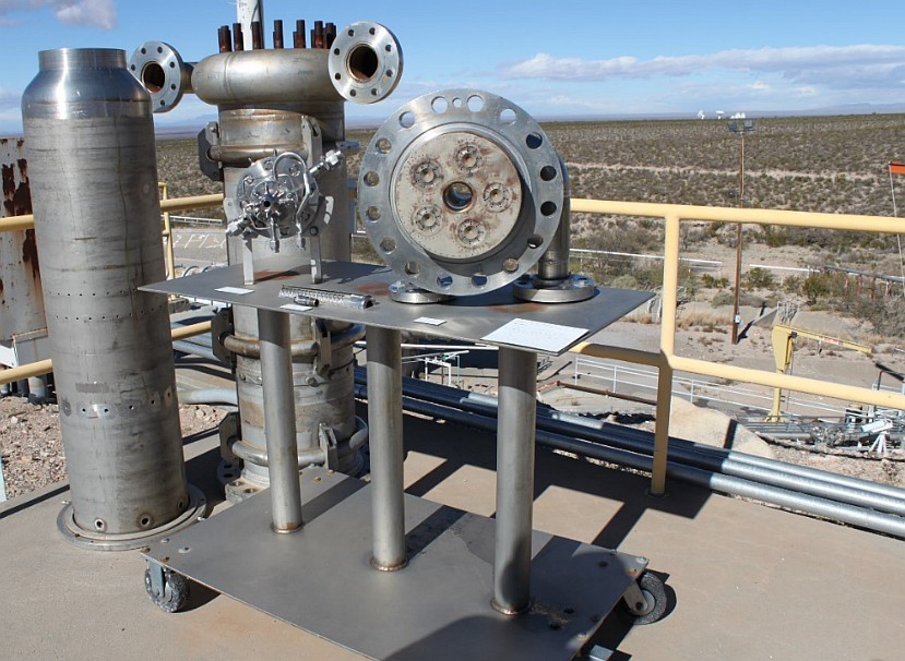
05/02/2020 at 21:45 • 0 commentsI had the exciting experience of a behind-the-scenes tour of NASA’s White Sands rocket engine Test Facility in Las Cruces, NM. The most notable engine tests were on the Apollo Command Module rocket engine and the Lunar Module (LM) Ascent and Descent engines in the 60s.
![]()
The first rocket engine test occurred here on September 22, 1964; this NASA facility in Las Cruces, NM has performed development and certification testing of space propulsion systems for manned and unmanned spacecraft in the cold void of outer space. (Image courtesy of Loretta Taranovich)
During my exclusive tour, I was able to experience what it was like there in the 1960s when the Apollo program was in full swing. Later, I also experienced the present day rocket engine test facilities and actually got a chance to go inside one of the Test Stands (TS) where active rocket engine testing under a vacuum is performed today for NASA and its contractors.
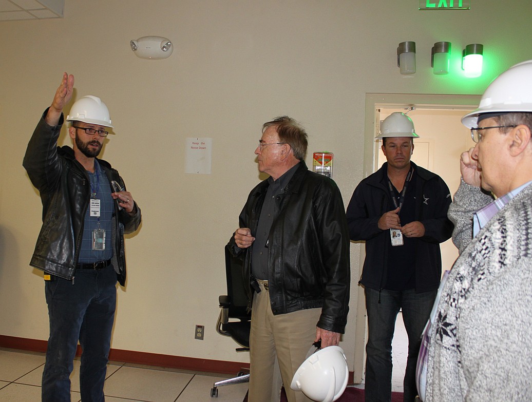
![]()
My guided tour of the test facility; Ray Melton, NASA retired engineer, is second person from the left (safety helmet in hand) and I am the fourth person on the far right side of the image. Melton was part of the NASA and contractor team at White Sands Test Facility (WSTF) working on the spacecraft propulsion systems that enabled the Apollo 11 lunar module (LM) to land on the Moon July 20, 1969 (Image courtesy of Loretta Taranovich)
![]()
One of the Test Stands (TS) is shown here with the domed top cover. That dome cover is lifted by crane so that the rocket engine under test can be lowered inside the dome via another crane and set into place for testing. (Image courtesy of Loretta Taranovich)
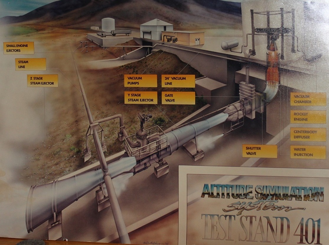
![]()
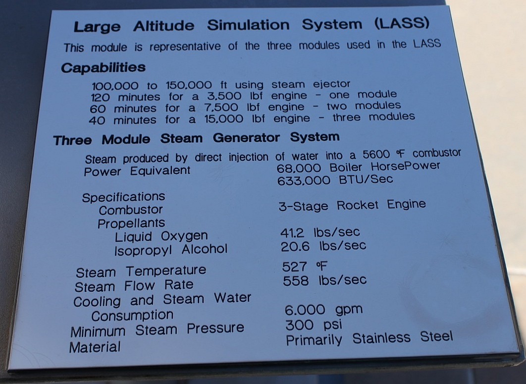
The Large Altitude Simulation System (LASS) specifications (Image courtesy of Loretta Taranovich)
This system provides a start altitude of about 35,000 m (115,000 ft) and maintains Test Stands (TS) 401, 403, or 405 at greater than 30,500 m (100,000 ft) during rocket engine firing. TS-405 can support even higher thrust levels when testing solid rocket motors.
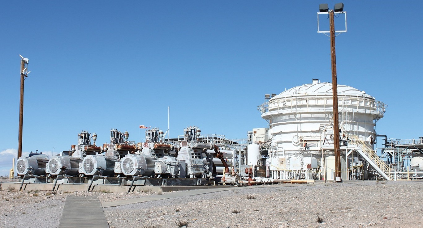
![]()
This photo shows components of one of three-module chemical steam generators that power large, two-stage ejector sets of the LASS. (Image courtesy of Loretta Taranovich)
NASA’s vacuum test stands simulate a propulsion system’s intended operating environment. This enables engineers/scientists to verify how a particular propulsion system will operate when it is put into service at a particular altitude level, even in the cold void of space. When a propulsion system is installed inside one of these enclosed test stand chambers, the chamber is evacuated to simulate altitude conditions. A vacuum is maintained during rocket engine firing within a sustained pressure environment of that which the spacecraft will experience in space.
![]()
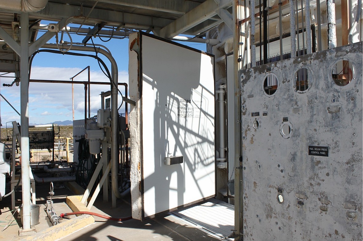
One of the Test Stands (TS) with the massive, thick electro-mechanical door that enables access to test personnel and later seals shut, tightly sealing the chamber preparing for evacuating the air inside and test firing an engine. (Image courtesy of Loretta Taranovich)
![]()
The NASA Cassini spacecraft is shown here, inside one of the WSTF Test Stands, firing its propulsion engines (Image courtesy of NASA WSTF)
I also had the neat experience of traveling below ground under the rocket test and monitoring facility. We journeyed down and were transported back in time as we walked across this lower level floor, passing by a 1960s set of vintage test racks and into a tunnel that had numerous cables running from the data monitoring and control facility to the rocket engine Test Stands.
The Fallout Shelter sign, in this lower level, brought me back to the 50s and 60s during my days in grammar school when we had air raid drills that prepared us to take shelter in the case of a nuclear attack by Russia.
![]()
A former Fallout Shelter was a remnant of the Cold War (Image courtesy of Loretta Taranovich)
As we walked on, I noticed a small round marking on many of the old floor tiles. Ray Melton explained that under those designated, marked...
Read more -
NASA lightning sensor network preventing a launch disaster
04/24/2020 at 21:14 • 0 commentsIn 2017 I visited NASA Kennedy Space Center, not the tourist center (Which is a very educational site as well), but a visit behind the scenes where not many non-NASA people venture.
One of the areas I asked to be taken was Launch Pad 39B. This was one of two Space Shuttle launch pads---the other was right nearby, at Launch Pad 39A, which is being leased by Space X.
I toured that Launch Complex 39B site which was being totally renovated for the Mars Orion program. The most powerful rocket in the world, NASA’s Apace Launch System (SLS) Block 2, will sit atop this trench behind us in Figure 1. The flame and exhaust from the four RS-25 engines will provide 11.9 million lbs. of thrust!
![]()
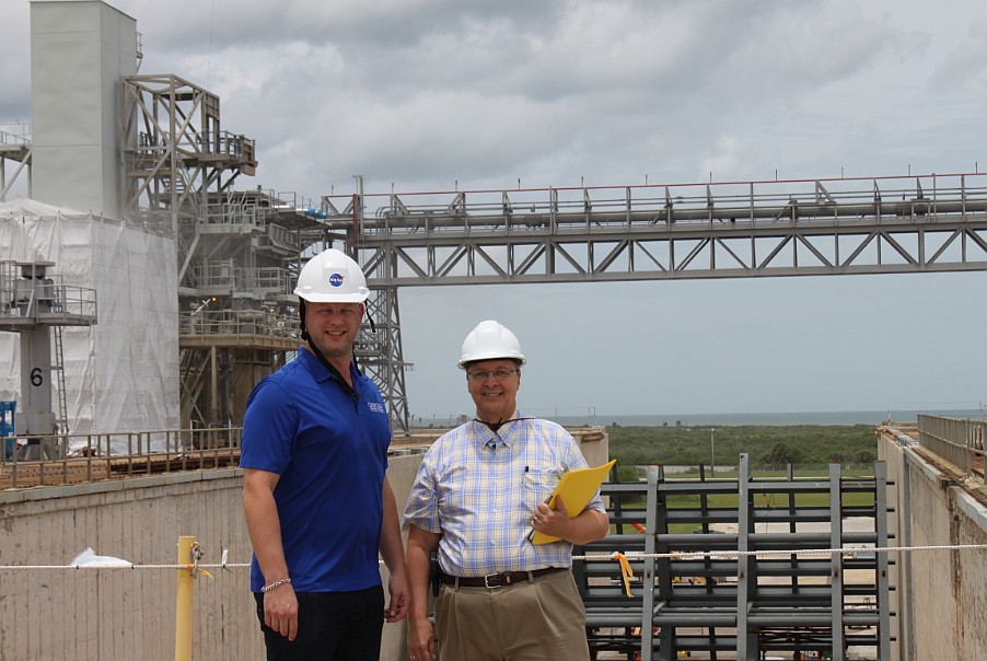
Figure 1 Nick Moss (left), Pad Deputy Project Manager, and me (right) are at Launch Pad 39B in front of the Flame Trench which is 490 feet long, 58 feet wide, and 42 feet deep. This launch pad was under major renovation for the Mars Orion program whose SLS rocket will launch astronauts to the Moon and Mars. (Image courtesy of Loretta Taranovich)
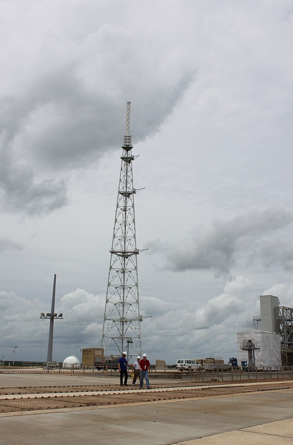
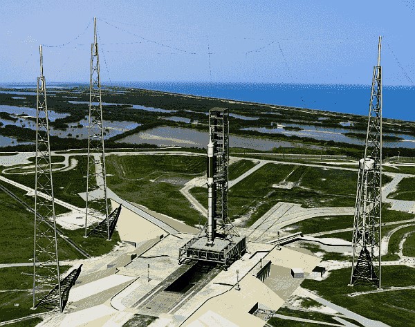
One area really caught my eye, that of the three large Lightning Arrestor towers (Figure 2) which prevent a spacecraft from being struck by Florida’s frequent, and sometimes dangerous, thunderstorms. A strong lightning strike to a spacecraft could wreak havoc on the electronics and end in disaster.
![]()
Figure 2 Three of these towers surround Launch Complex 39B connected at the top to each other with stainless steel cables arranged in a pattern (See Figure 3). The construction of the foundation of these towers includes 216 concrete pilings under the ground as far as 55 feet—that’s a solid ground that a lightning bolt will be happy to enter. (Image courtesy of Loretta Taranovich)
There are three tall steel masts with down conductors which will divert the surging electrical current from a powerful lightning strike safely away from the rocket and into the very excellent ground. The three towers are all connected at the top to each other with stainless steel cables arranged in a pattern. See Figure 3. The large stainless steel cables are strung between three, 594-foot tall, towers constructed of steel and fiberglass. This is known as a catenary wire system. The construction at the foundation of these towers embeds 216 concrete pilings under the ground extending as far down as 55 feet. Alltec Global Systems explains this lightning arrester technique best here.
![]()
Figure 3 The spacecraft, atop the Launch System rocket, will fly through an opening in between the stainless-steel cables tightly strung above and connected to three masts. (Image courtesy of Loretta Taranovich)
The towers are not simply to divert a lightning strike, but are also equipped with weather monitoring systems which can help predict weather and the likelihood of lightning occurrences. Each tower has four arms containing weather instruments at different height levels on these masts. At each level wind velocity and direction, relative humidity, and temperature is measured and that data is sent to operators monitoring and analyzing that information before launch. You would be surprised how different weather conditions can be at each different level on the mast; those four arms, at each increasing height level on the tower, give a more complete picture of how the weather patterns are behaving at any instant in time.
Also, in the event of a severe tropical storm and the area may have been evacuated, computers in the Pad Terminal Connection Room (PTCR), in a basement area below the Launch Pad surface, will store all of the data for future analysis. Weather prediction is a critical element in modern launches.
Finally, the perimeter of the Launch Pad contains nine down-conductors and also four B-dot (The time-derivative of an Inductive magnetic field or dB/dt) and five D-dot (The time-derivative of electric flux density or dD/dt) stations that will identify when and where lightning has struck,...
Read more

Steve Taranovich's pages
I am an engineer and tech writer. I have traveled behind the scenes to many NASA locations for articles and my book. I'm a 'Geek


