Daren Schwenke
-
Maple syrup anyone?
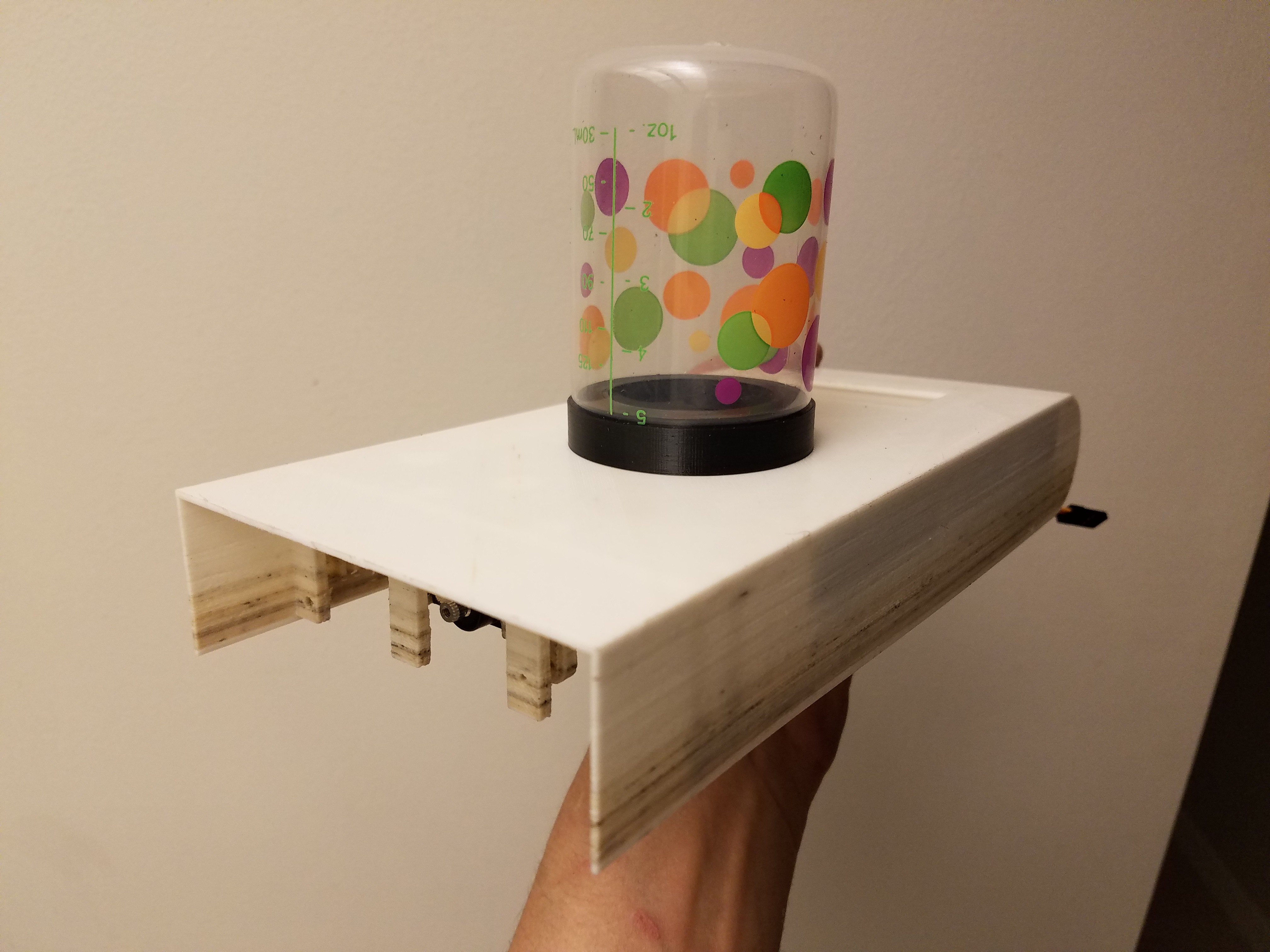
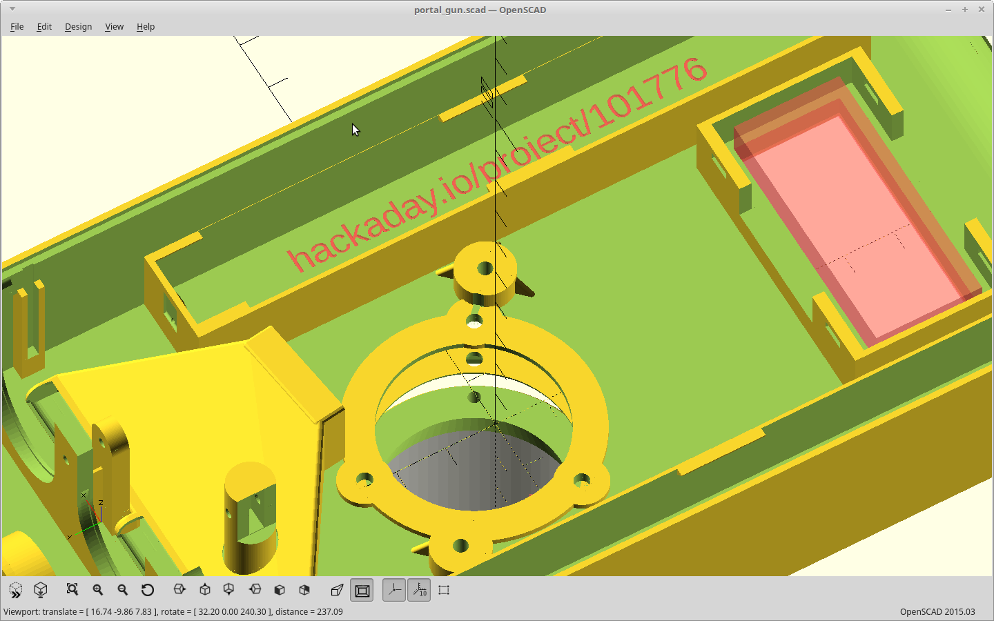
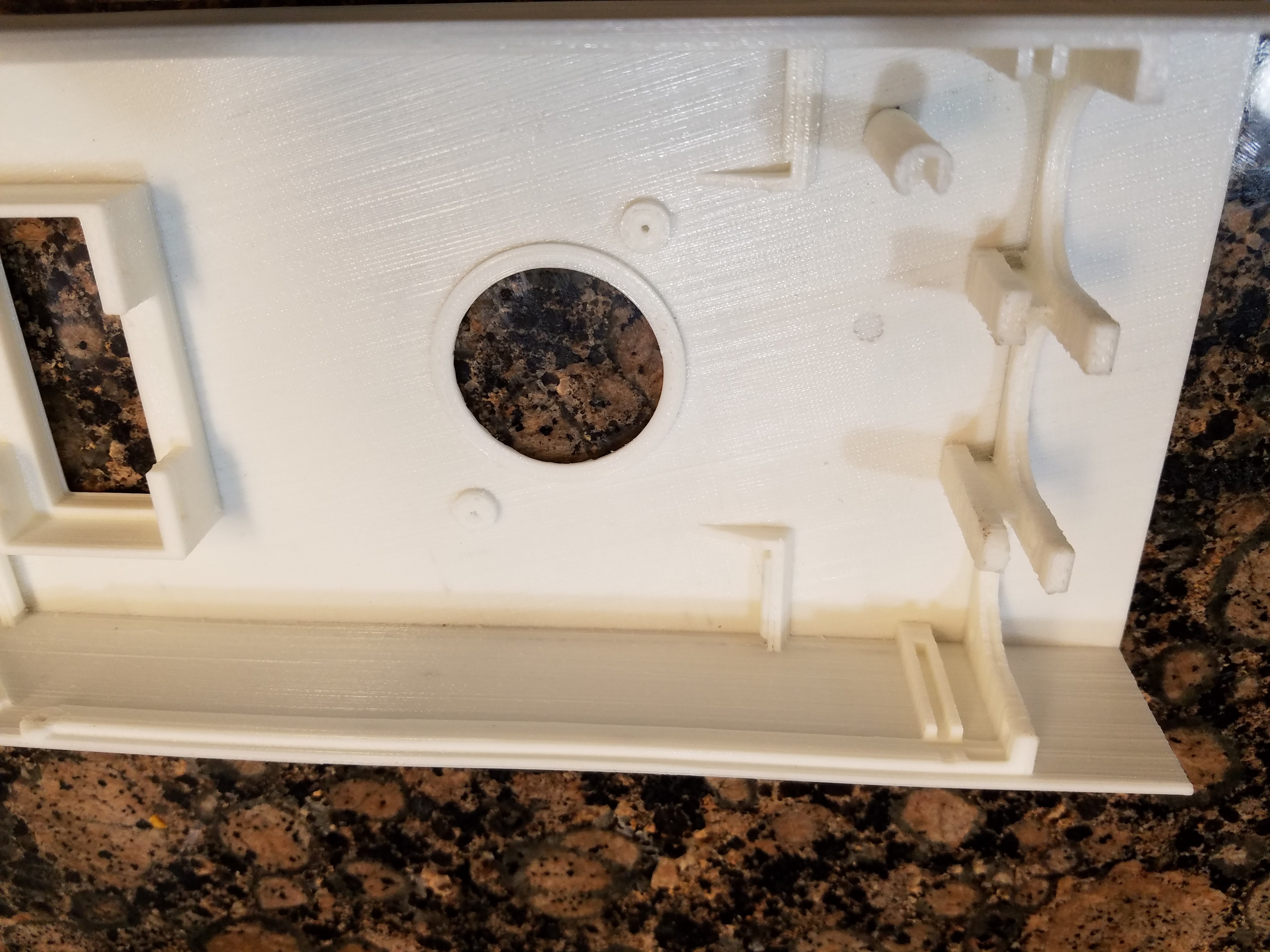
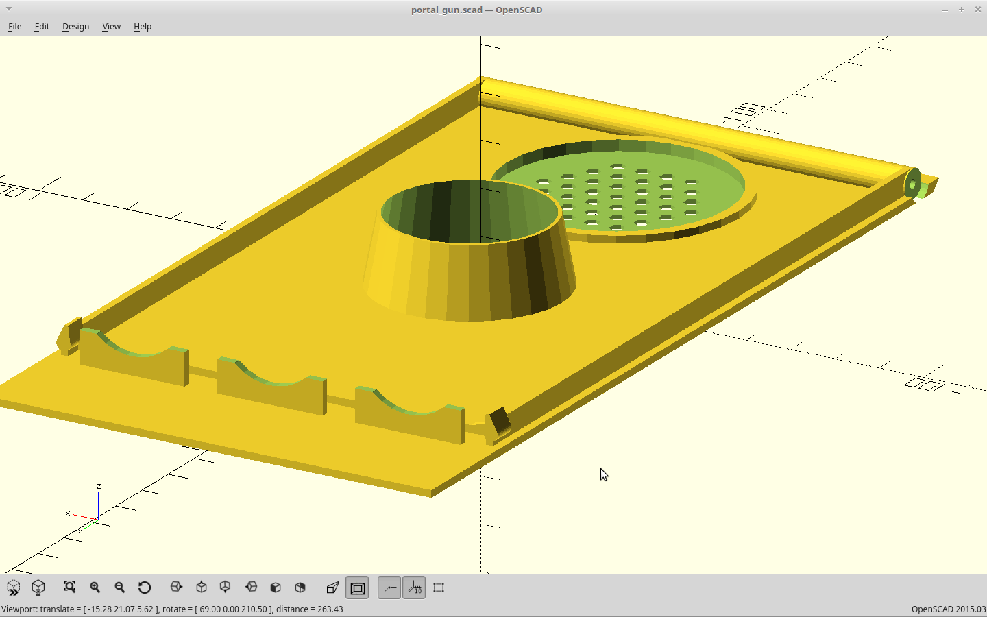
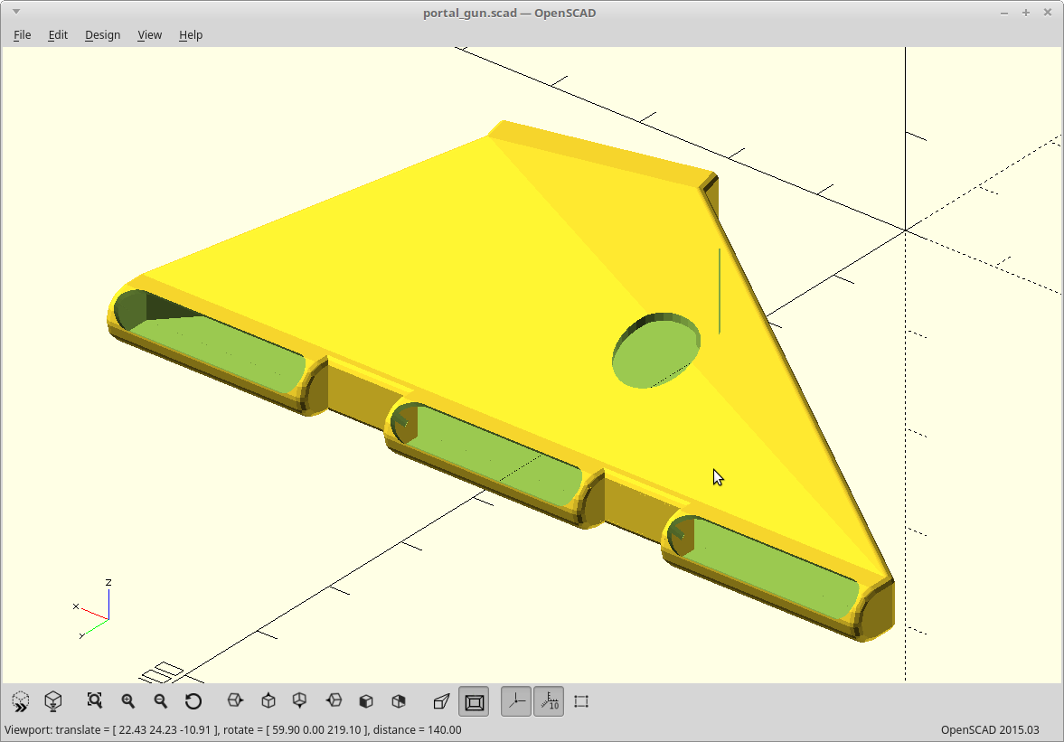
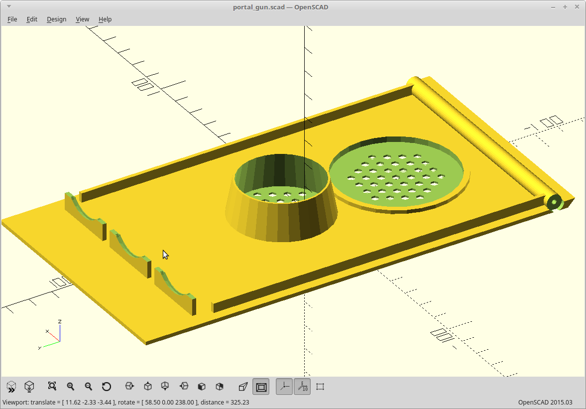
04/11/2018 at 04:24 • 3 commentsIt finished. I realized at 99.9% done I just could have lowered the set point and had the same effect as increasing the speed. Duh. Now the whole area smells a lot like burning maple syrup, but at least I have a print for testing how things fit.
I have a polka-dot portal fluid container stand-in as I destroyed the original trying to make the top bulge out evenly.
![]()
The fit looks pretty good though. I still tweaked the clearance a bit so the inside ring will sit lower. I also realized I put the portal fluid LED recess on the outside instead of the inside of the body. It would be rather difficult to hold that ring in place with the LED in the way. Fixed.
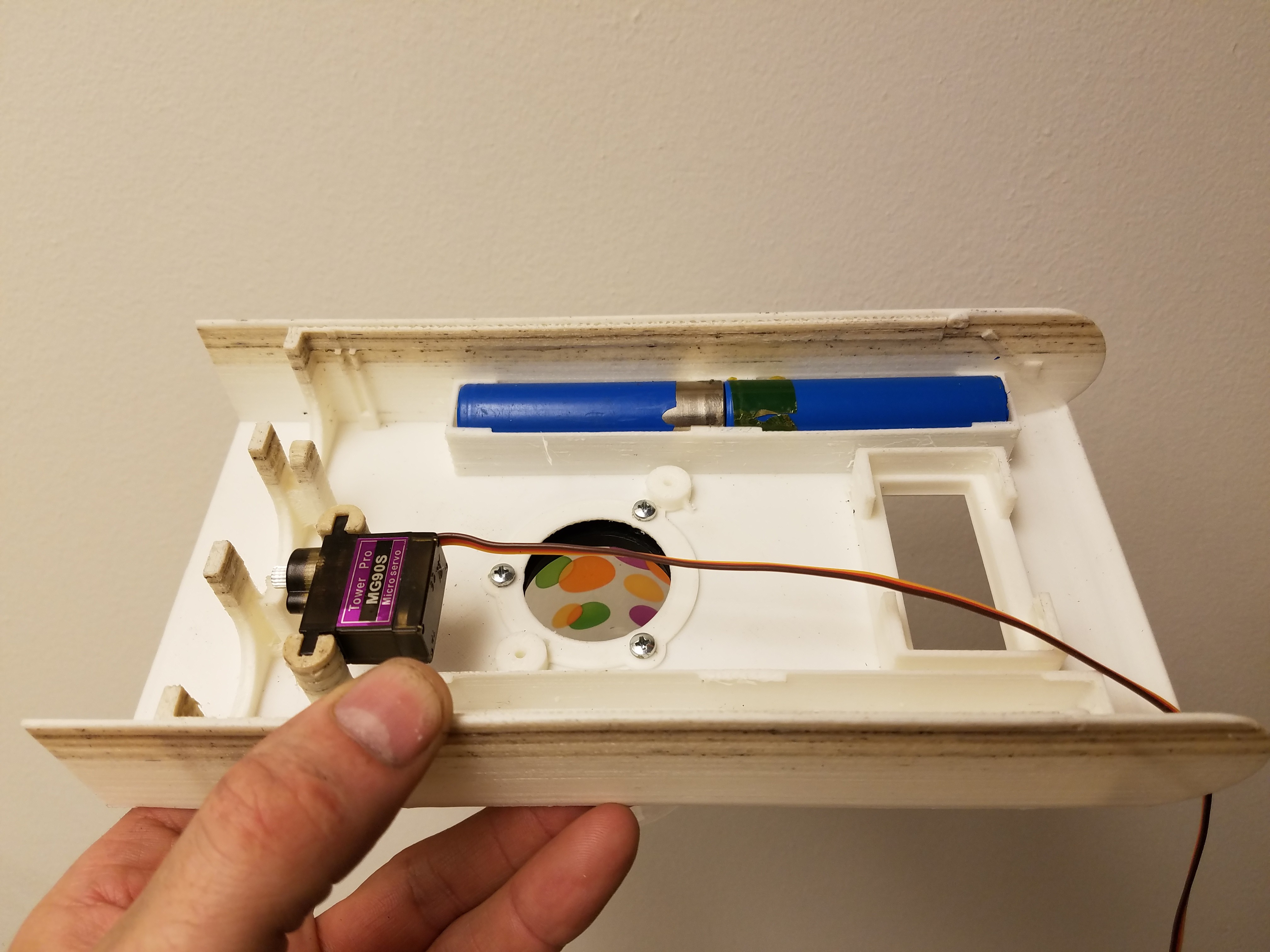
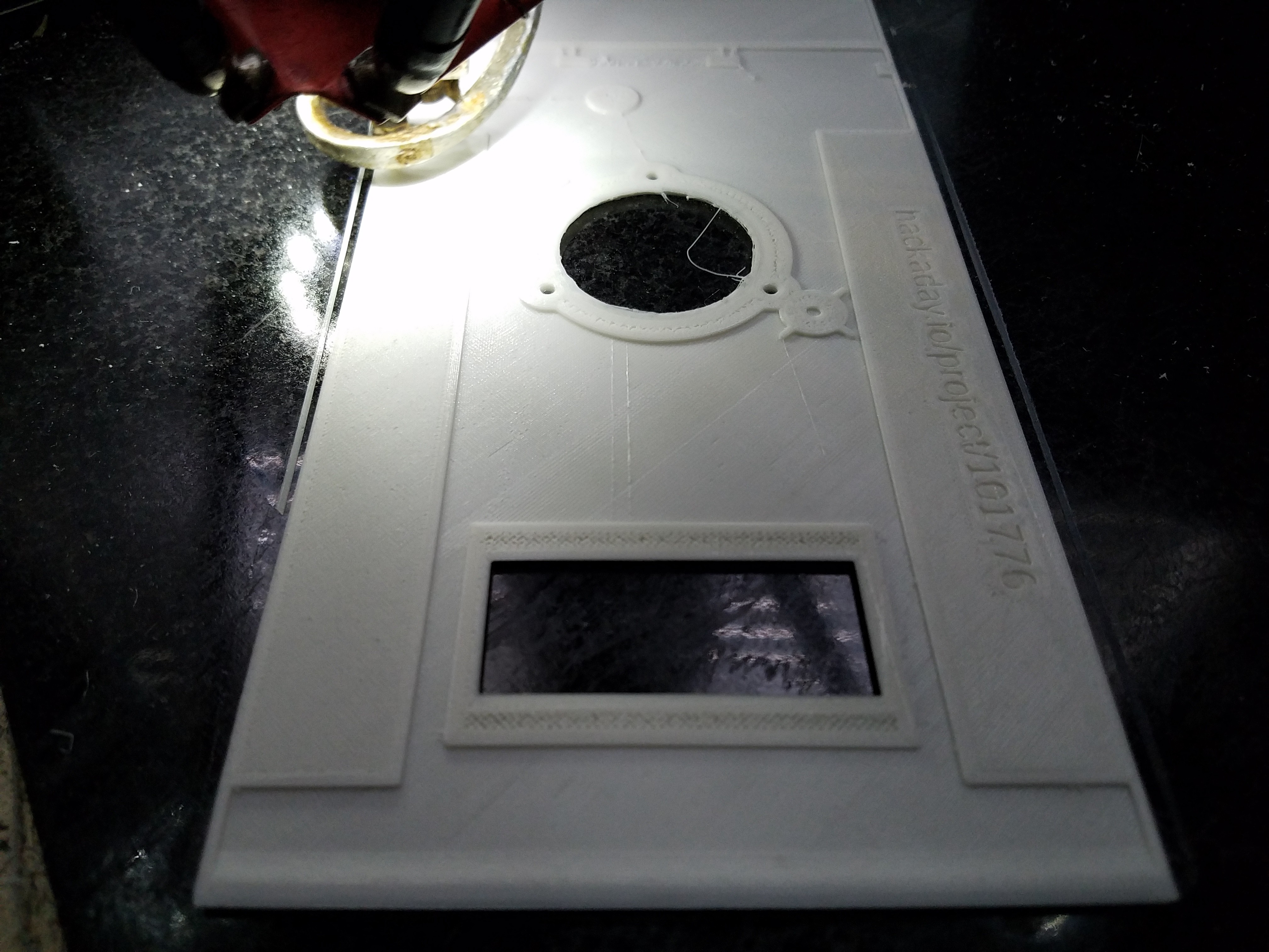
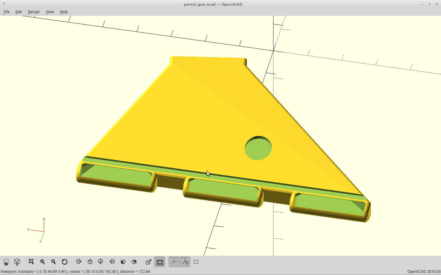
I made the battery holders part of the body now as it saves a bit of plastic. The length is perfect. The diameter is like .25mm off.
![]()
Well it turns out my 18650's are exactly 65mm long, but are actually ~18.3mm in diameter. Measure twice, print once I guess.
It occurred to me I could use the 3xAAA battery holders from my discarded flashlights instead here, but I don't think they would stand up to the current demand for very long. The whole gun will come in somewhere around 3.5 Amps draw.
Servo mount looks good.
Printing again..
-
Temperature regulation, by extrusion rate.
04/10/2018 at 23:40 • 0 commentsWell I have a little unintentional experiment running.
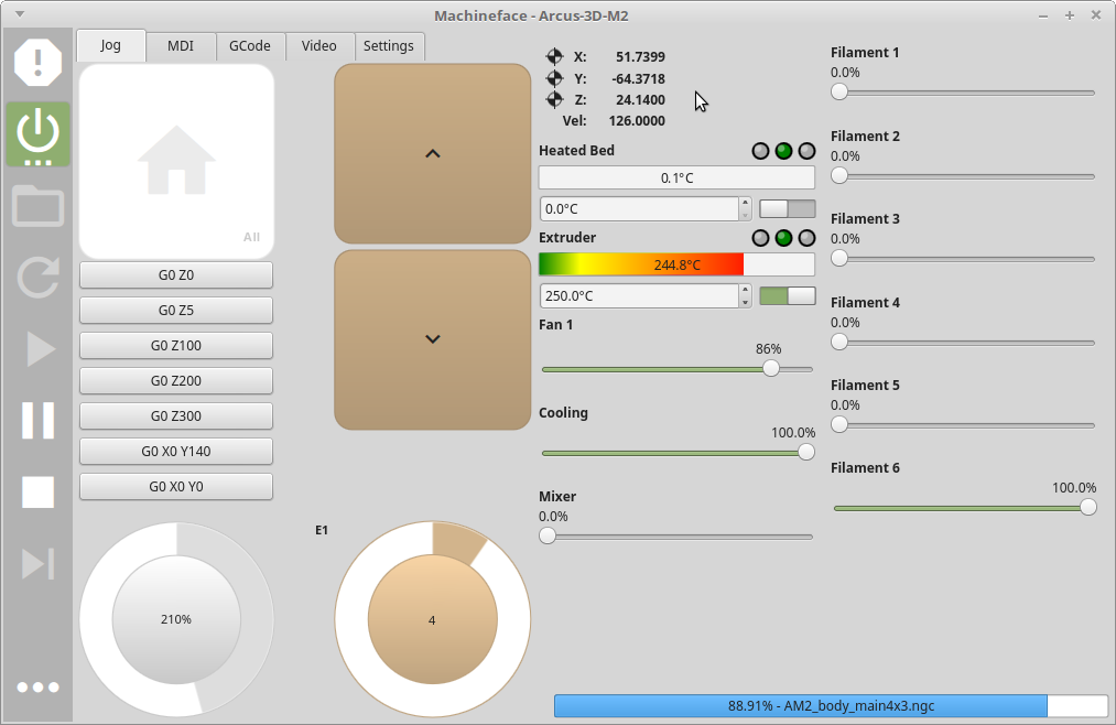
The printer started to smell a little stronger than usual, so I looked at it. The thermistor code has stopped reporting, so it is now running locked to whatever PWM rate it was feeding the extruder heater at that moment.
As luck would have it, the PWM rate it got stuck at is a little hot, but almost right.. So I've increased the print speed to 125%, and now the temperature is within range. :)
The print is 3/4 done, so it would be a shame to stop this 17 hour print now.
We'll see if this works..
EDIT: Temp was creeping up. More detail in upper layers = less extrusion. I'm now at 185% to maintain temp, but it's working..
EDIT: Now at 210%...
![]()
EDIT: Now at 265%. Infill is at ~160mm/sec and perimeters are at 80mm/sec. 9% left to print....
-
Fluid retention, of the portal kind.
04/10/2018 at 18:02 • 0 commentsMade a two part retainer for the portal fluid container. It fits inside the lip left when you cut the top off the baby bottle, and bolts through the body.
![]()
![]()
So... I've made enough changes that I'm reprinting everything.
I've worn out my last .4mm nozzle. The prints were getting pretty sloppy looking when I did the handle print, so that leaves pretty much every other size from 1.0mm to 0.1mm in my supply bin. I mainly use 0.4mm.
I went with 0.3mm and changed the <nozzle_dia> in my source so my wall thicknesses are all exact multiples of this, re-rendered, re-sliced, and I'm re-printing. Slowly...
About 10 hours into the first 17 hour print.
![]()
-
Printed, changes needed.
04/09/2018 at 21:05 • 0 commentsPrinted it out. The handle fits the body perfectly and hides the seam pretty well. The V notch I put in the ends lines everything up for you.
![]()
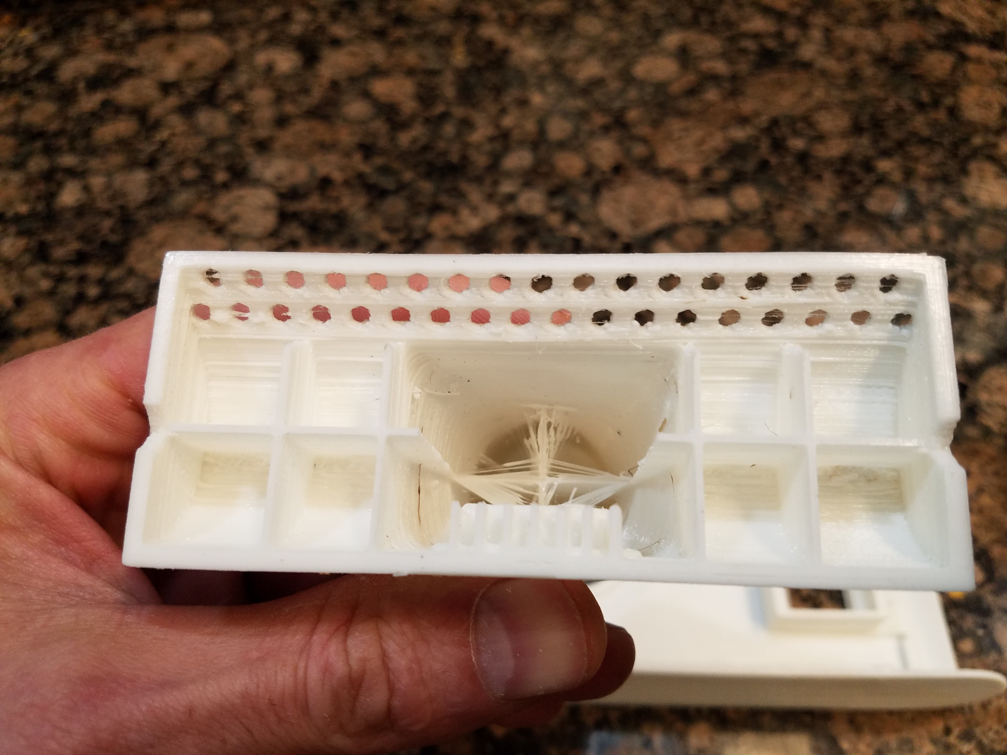
The bottom looks great too. The hexagons filled in a bit though. I may change them back to cylinders so I can drill them out after.
![]()
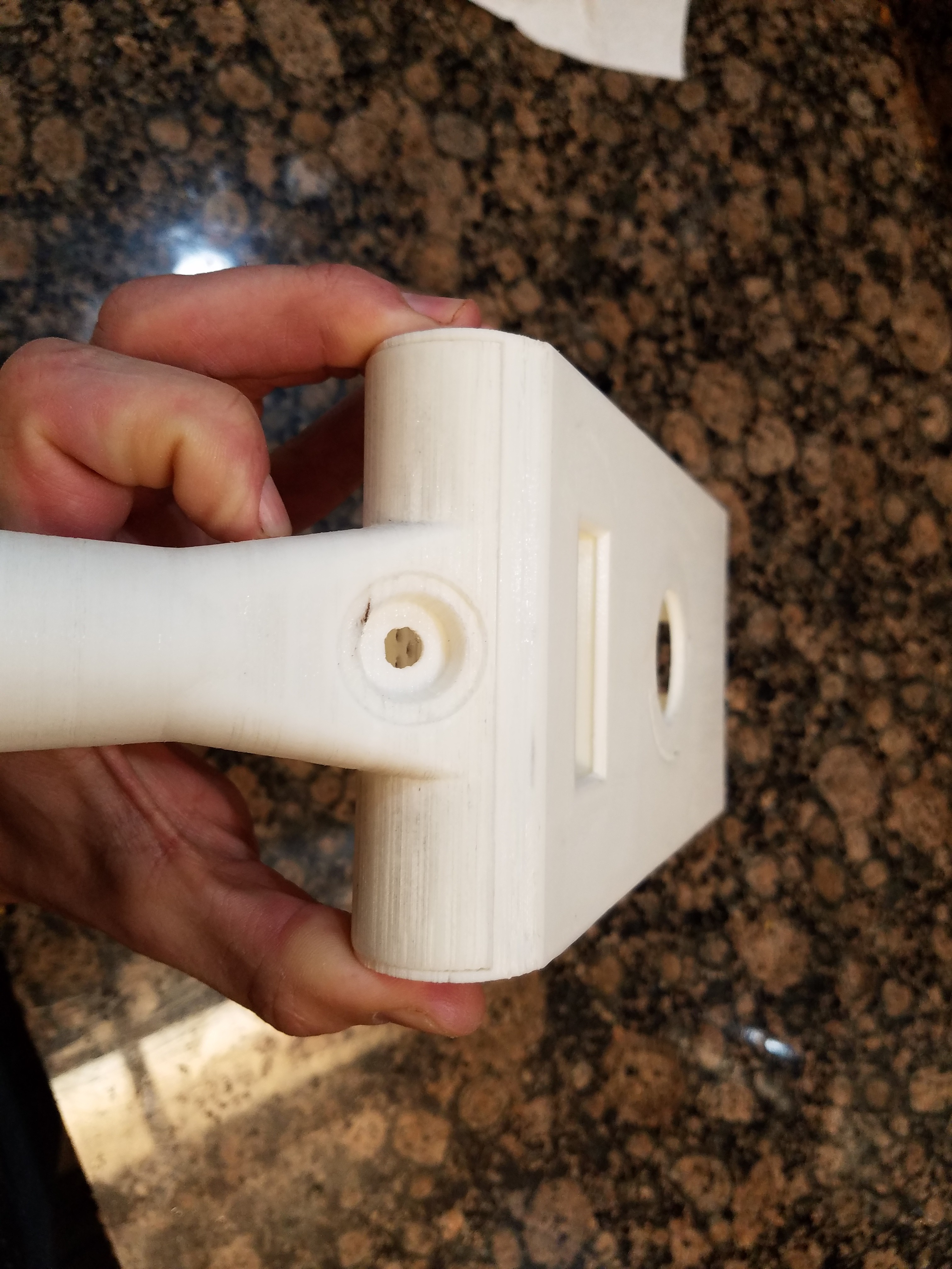
The handle is also plenty strong, and so should withstand some abuse.
![]()
But, I snapped off both fan mounts and one servo mount in about 3 hours of handling it.
![]()
I printed this at 90mm/sec, 2 walls, and 50% infill so it's kinda my fault. They may have survived at 4 walls, but I think I'm going to move the fan up slightly and go back to using screws to mount it.
The servo studs have been modified and are now 10mm instead of 7mm. That should do it.
-
Modeling, done.
04/07/2018 at 06:07 • 0 commentsFinished the remainder of the modeling work.
![]()
Battery mounts, encoder knob, encoder mount, fluid globe, display mount, and cover snaps done.
The handle got a recess so the encoder doesn't make the knob stick up.
![]()
The body had the battery mounts moved to the edges, and now I'm using 4 18650s.
![]()
I sized the display cutout for a 4 digit .54 in LED display.
The top cover got it's snap closures and the speaker moved back a bit.
![]()
The fan duct got improved flow.
![]()
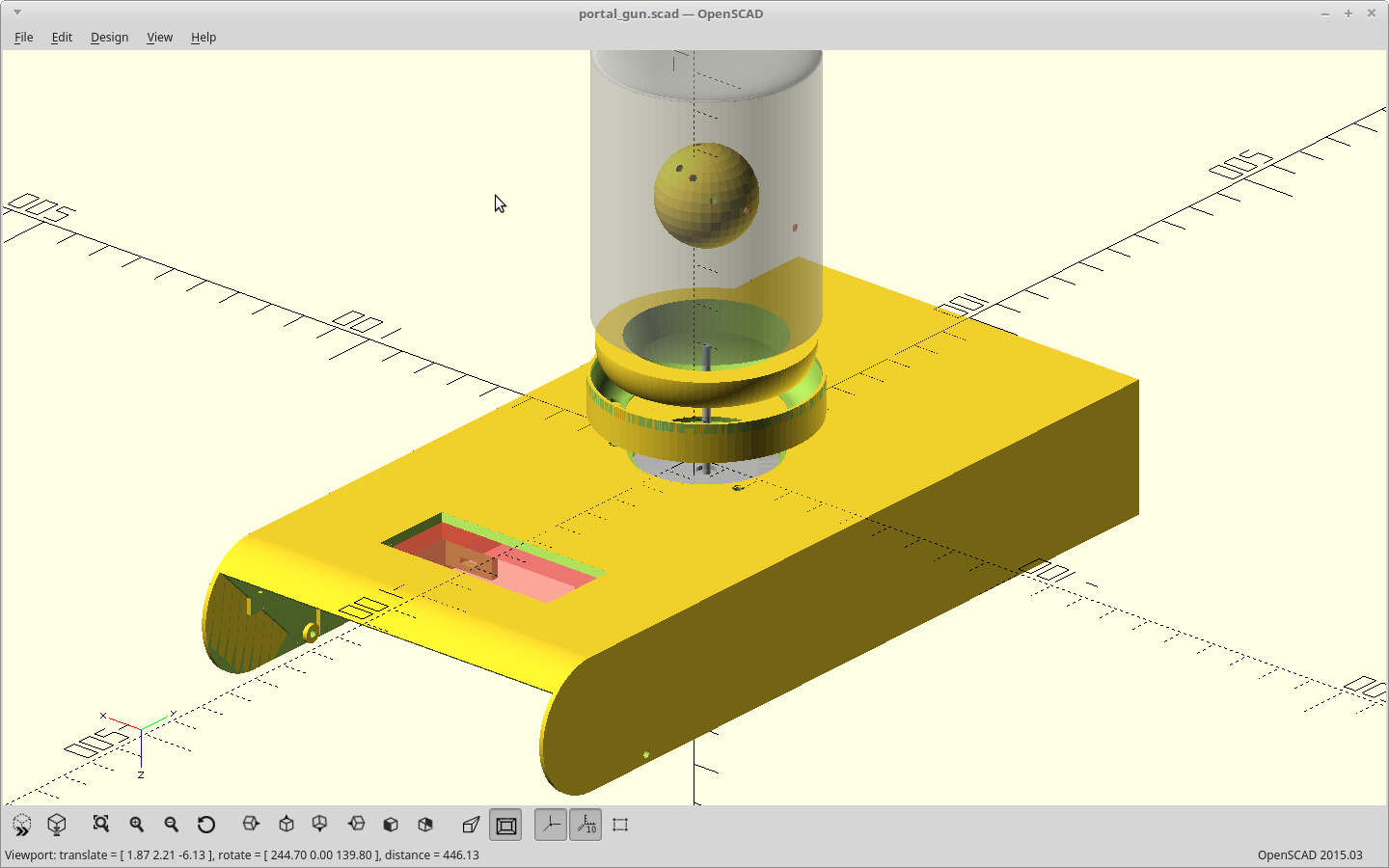
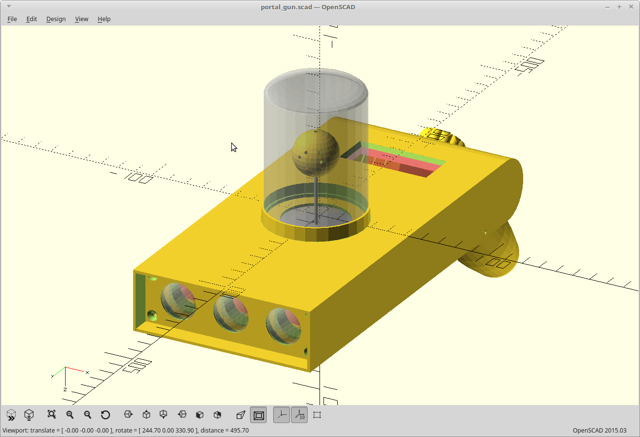
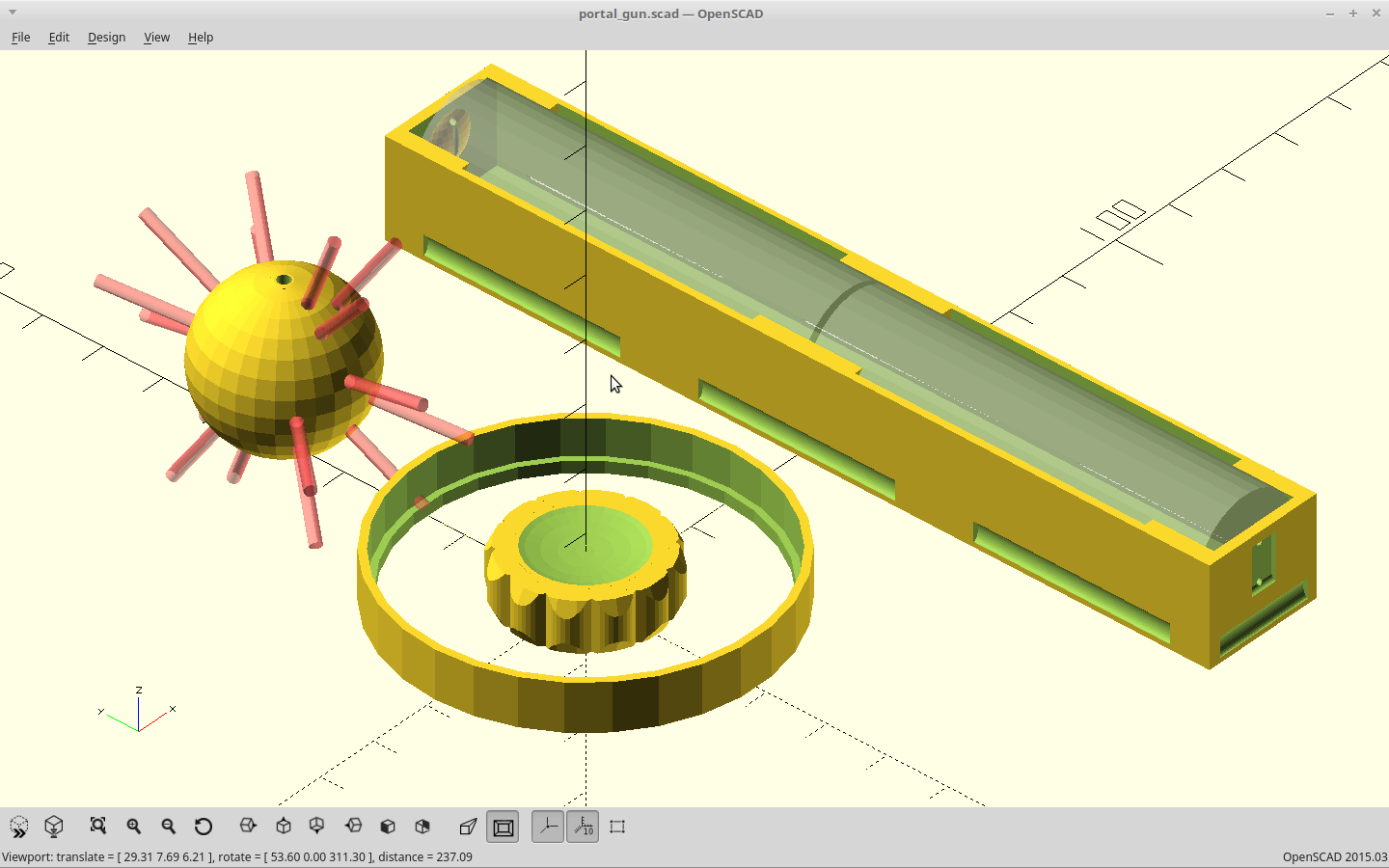
And.. the remainder of the parts with changes.
![]()
The spiky thing is the globe for the fluid simulation, the ring is the retainer for the fluid bottle, and the knob... well... is a knob now.
The battery carrier is now a 1x2 and I'll be using two of them, instead the old layout of a single 3x1 carrier. It fits better that way and leaves the middle largely open for the Arduino and mosfets.
Time to start printing, and on to the electronics.
-
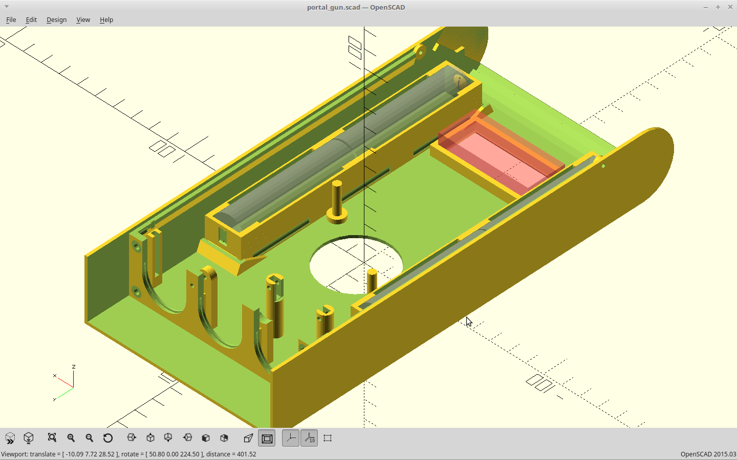
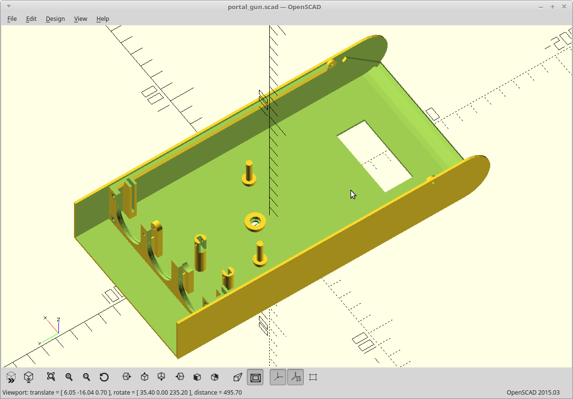
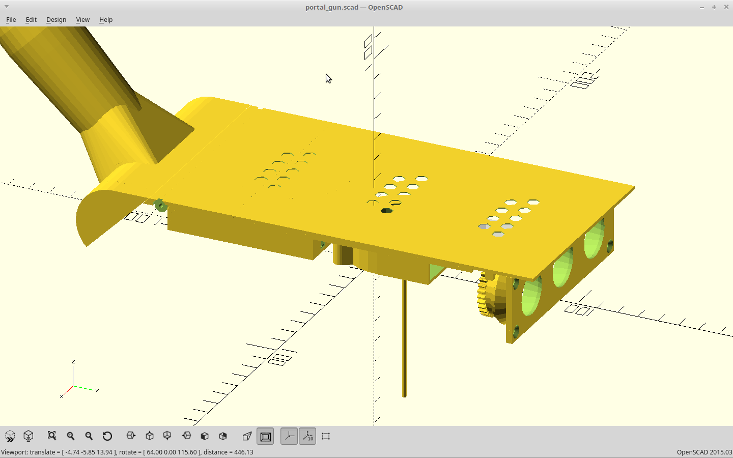
Show me your body.
04/05/2018 at 18:34 • 0 commentsWell here it is.
![]()
The fan mount got changed to studs, the servo mounts were changed to posts and moved up, and the mounting slot for the LED PCB was added.
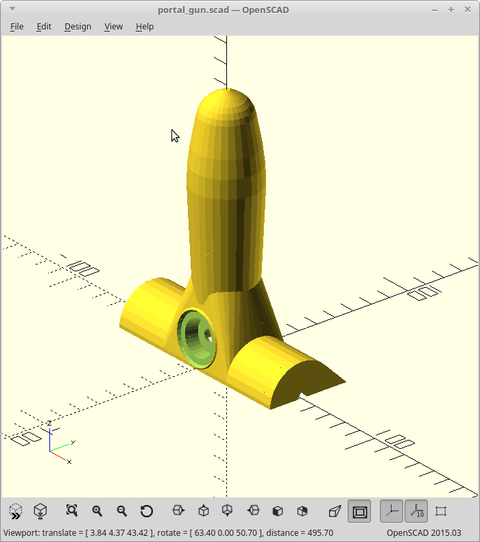
Next, the handle, which is sized to permanently glue to the body.
![]()
The center two ribs are break away, while the remainder support the rounded edge during printing for clean bridging. I also moved the cooling exhaust to the handle bottom I'll get less light leakage than having it right below the LED PCB, and perhaps the front to back circulation will cool the entire body then. We'll see just how hot the exhaust from the LEDs gets when it's blowing on your hand..
The fan duct.
![]()
It routes the cooling air between the LED PCB and the image discs, which should keep them both cool enough. I broke down and used minkowski() for this one. Minkowski is powerful, but must be used sparingly. Notice the hole for passing the servo stud through, which is why they are round now.
And the cover.
![]()
Center is the duct to the fan, right is the speaker mount. It's still missing the battery mount and tabs for snapping it closed. The battery will mount over the speaker, and the tabs will go between the end of the stiffening rail and the gear retainers.
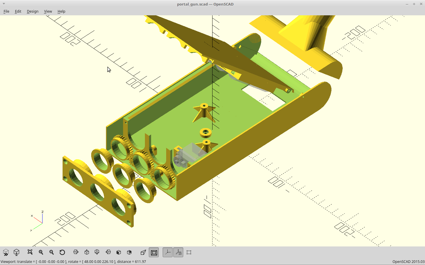
What it looks like from the outside.
![]()
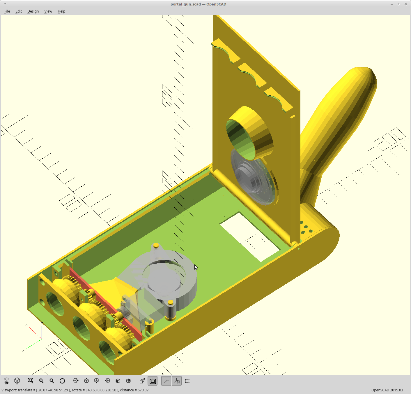
And, all together.
![]()
The red panel is the stand-in for the LED PCB.
Almost there...
-
Let it flow.
04/05/2018 at 08:47 • 0 commentsMoved some stuff around and changed the cooling to flow from top to bottom between the LED's and image discs. This should keep both of them from melting down.
Generated the matching cooling duct and added the exhaust holes for this change.
![]()
I also decided to switch to making a PCB for the LED's. I think that will be easier than modifying the existing boards and since I'm blowing across the front of them, I hope I can get away with less copper and no heat sink. We'll see.
So for modeling, all that I can think of left to do is...
- Cover snaps
- Display bezel (I have yet to pick a display)
- Battery carrier mount/snaps
- Fine tune the control knob design, and maybe make it an encoder.
-
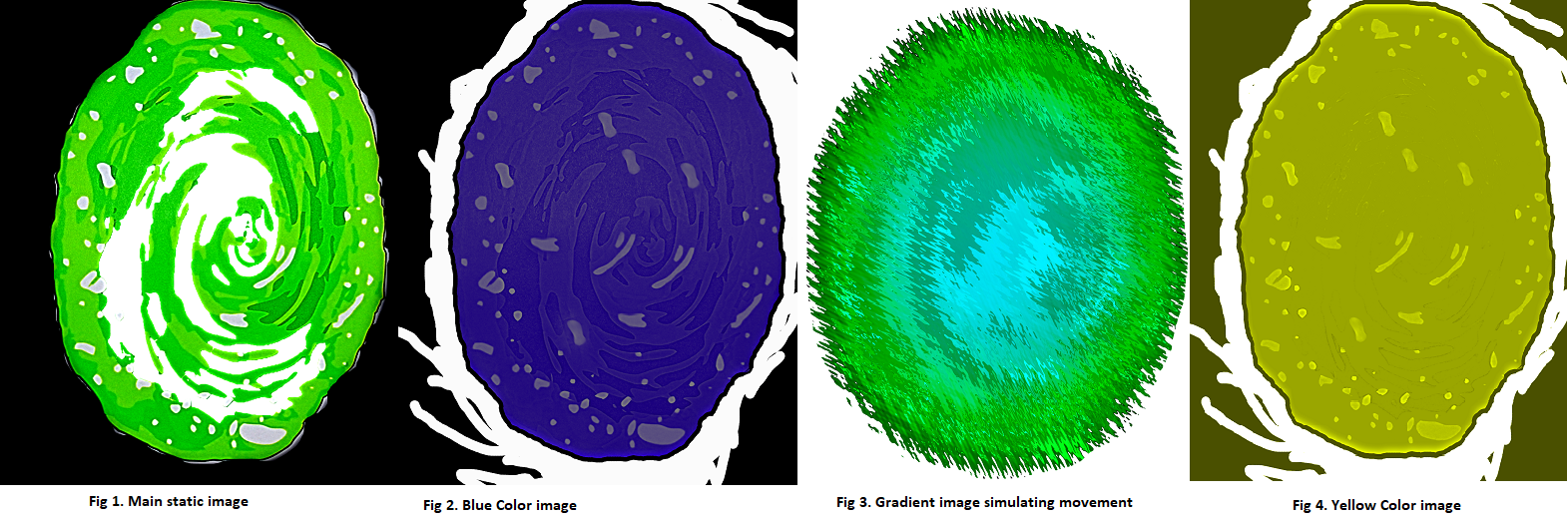
Making a Vortex In Photoshop...
04/02/2018 at 18:54 • 0 comments*UPDATE* 4/03/2018
2 more possibilities:
![]()
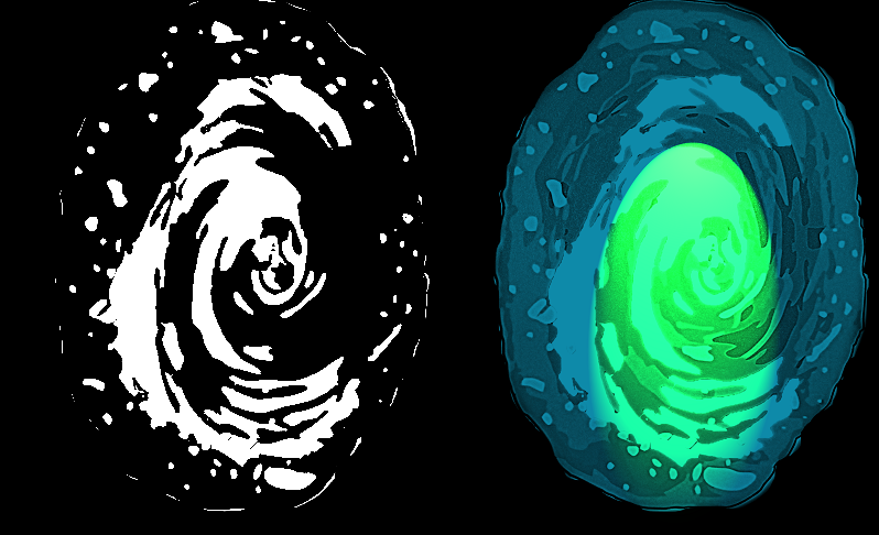
Well, I'm still working on several concept proofs, but I've learned quite a bit about the "real" power of Photoshop, I thought I knew it...Huh, was I wrong, I've only scratched the surface of it's capabilities. So here are some more ideas I had using different layers and color schemes and effects:
![]()
Image 1 and image 3 would go together as image 1 is cut like a stencil so image 3's motion and color spin mainly through the stencil openings. Images 2 and 4 are for color mixing and contrast.
Now indulge me for a second here, I came up with my interpretation of an Interstellar vortex type blackhole engulfing an entire star system, these are 2 GIF images (with motion,) 1 image is only 400 x 400 pixels, the other is 2500 x 2500 (HDTV size and quality!)
![]()
Huh, I'm going to have to upload the HDTV GIF as a Zipfile...too big to upload here :)
-
Speak and breathe.
04/01/2018 at 07:25 • 0 commentsI need to let air in and out for cooling my LEDs, and let the sound from the speaker out. This means holes... but I don't really want them.
So far I've been able to maintain the dimensions of the original gun and it would be a real shame to mess with that too much.
I think I can keep all the holes I need on the bottom panel though.
I could probably get away with not cooling the LEDs externally as long as people don't try to use this as a flashlight, but you know someone is going to do it and then it will melt down.
So for cooling, either the intake or exhaust needs to be ducted to the outside. It's a lot easier to duct the intake here as the exhaust has gears and such moving it it, so that's what I'm doing.
For the speaker, it needs to mount directly to some panel to isolate the two sides of the speaker from each other. If you don't do this, you lose like 80% of your volume and pretty much all of your bass response.
Problem is, I'm pretty much out of room if I want to keep my scale dimensions. If I put the speaker in the center, it intersects the fan duct. Moving it forward, there isn't enough room between the fan duck and the gearing. Moving it back, I got the battery.
So I toyed with making the top panel really thin and letting the speaker try to transfer through. A quick experiment told me that sucked. Virtually all the high frequencies were gone.
So I think I'm going to raise up the battery carrier and mount the speaker under it.
Here is about what the holes I need will look like.
![]()
Left is the speaker, middle is the air intake, right is exhaust.
I am going to get a lot of light leaking from the forward set of holes, but I think I can fix that.
Working on it.
EDIT: We took a couple days off here to enjoy our new toy and take in the Falcon 9 launch, but now back at it.
I've settled on smaller holes and more of them. They still occupy a hexagonal pattern and have an even multiple of <nozzle_dia> between them. This lets the slicer trace a nice continuous path with no gaps when routing the walls. I also corrected the fact that I forgot to rotate the hexagons 30 degrees so the edges line up.
The overall size was adjusted with the height now being 34mm for less plastic and better scale for the front bezel. As every dimension not tied to components scales with the height, the whole thing is smaller now. This puts the largest component at < 200mm so pretty much anyone can print this now.
-
Split.
04/01/2018 at 02:49 • 0 commentsI decided to split the handle from the body. This will let smaller 3D printers "handle" it. :)
It also avoids having to printing the bottom rounded edge as a bridge as the seam to the cover mates with the handle, which is now printed standing up.
![]()
Interdimensional Portal Gun
A 3D printed portal gun, which projects animated portals.