Close
0%
0%

Pony Bot

A robo-pet

Similar projects worth following
Put servos on a cutout of a pony. Add ESP8266 for moving them. Try to figure out how to make it do something funny.

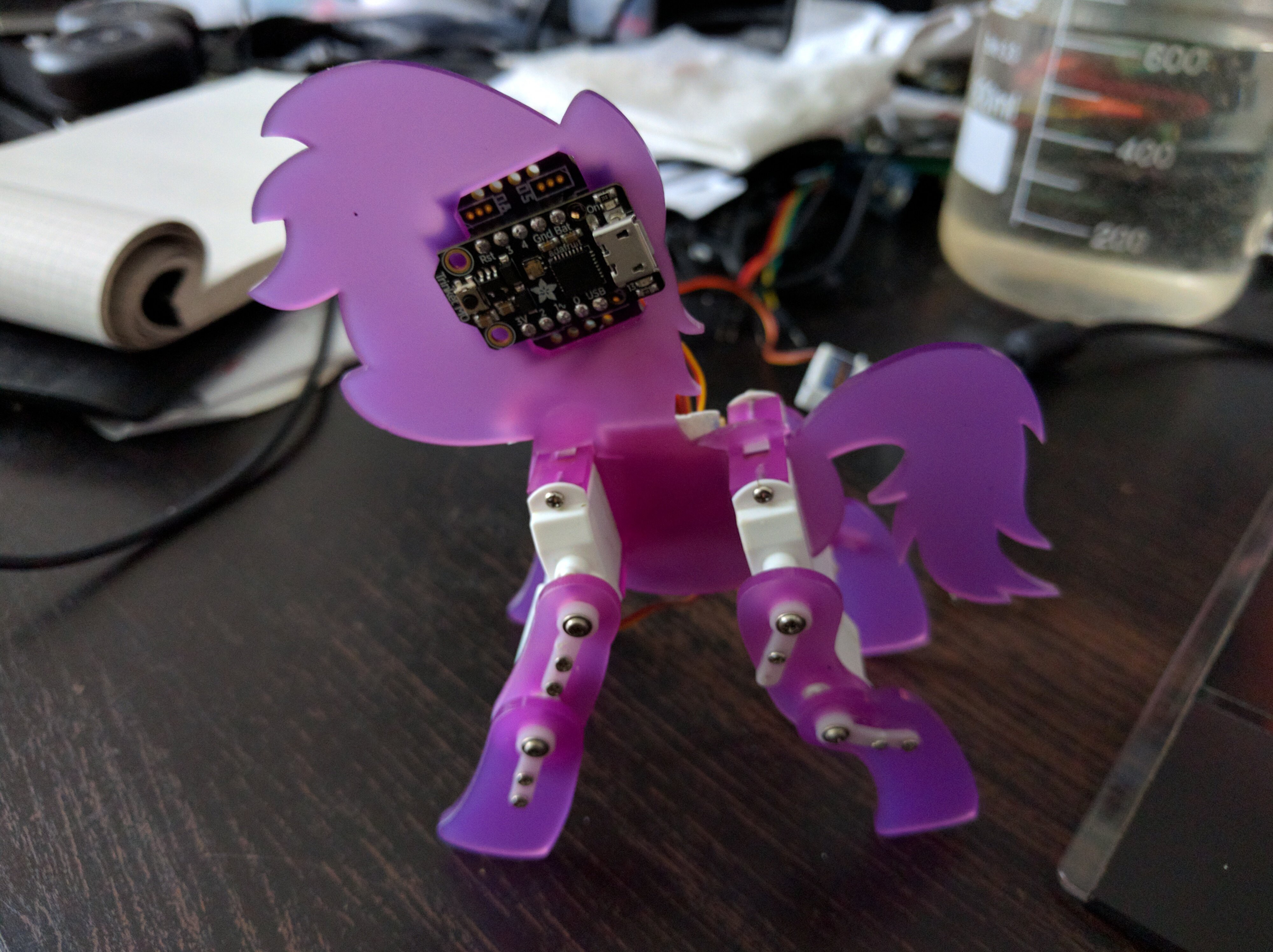
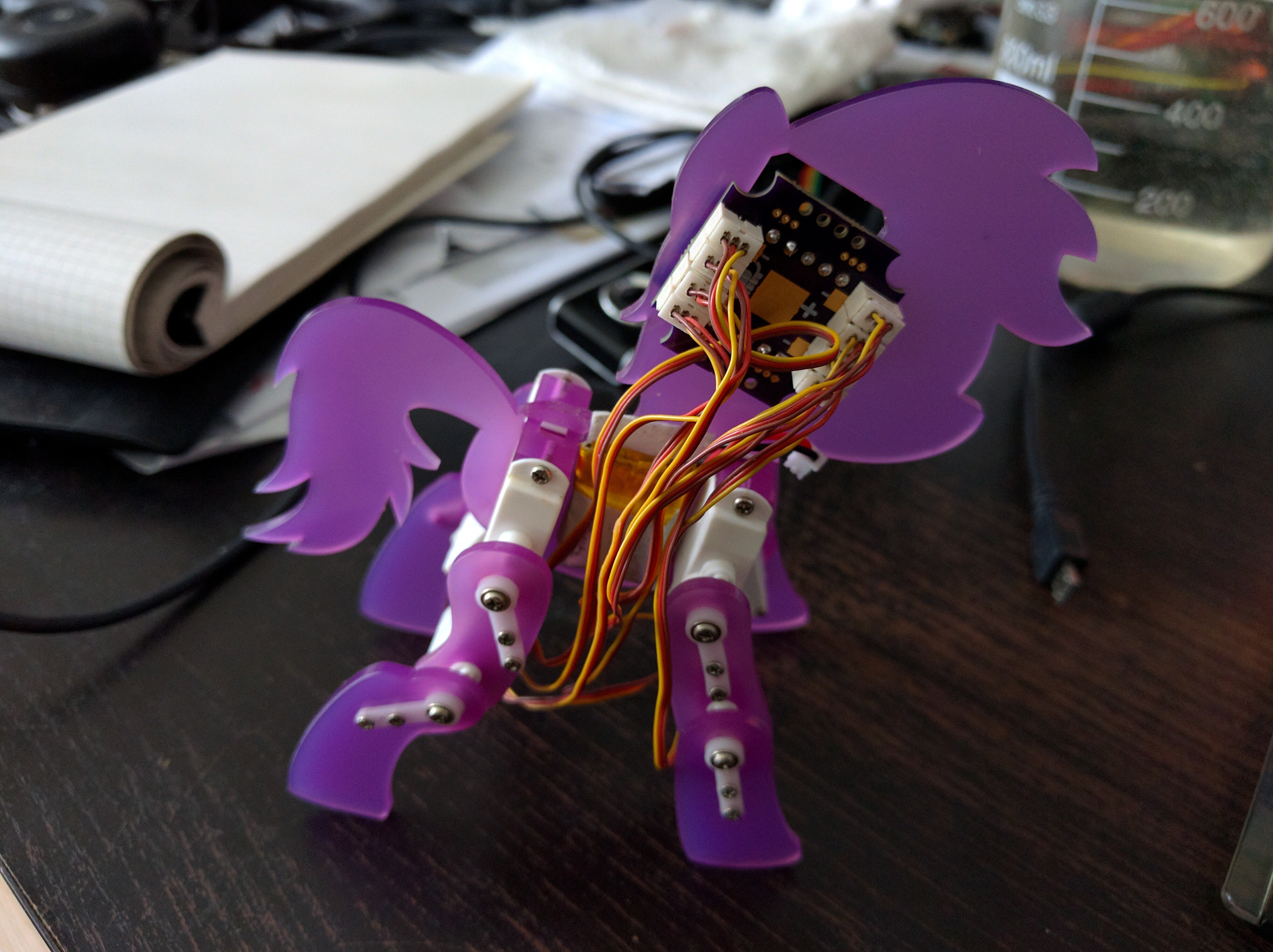
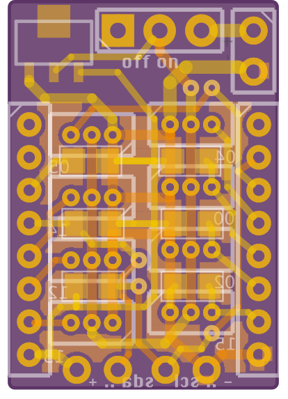
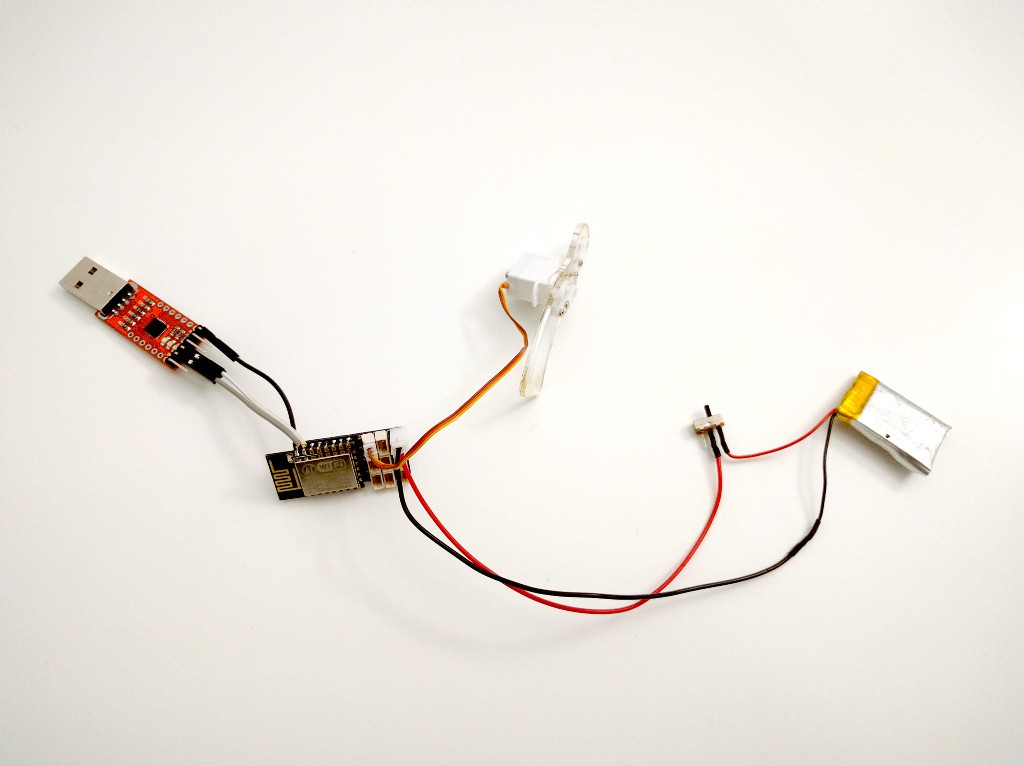
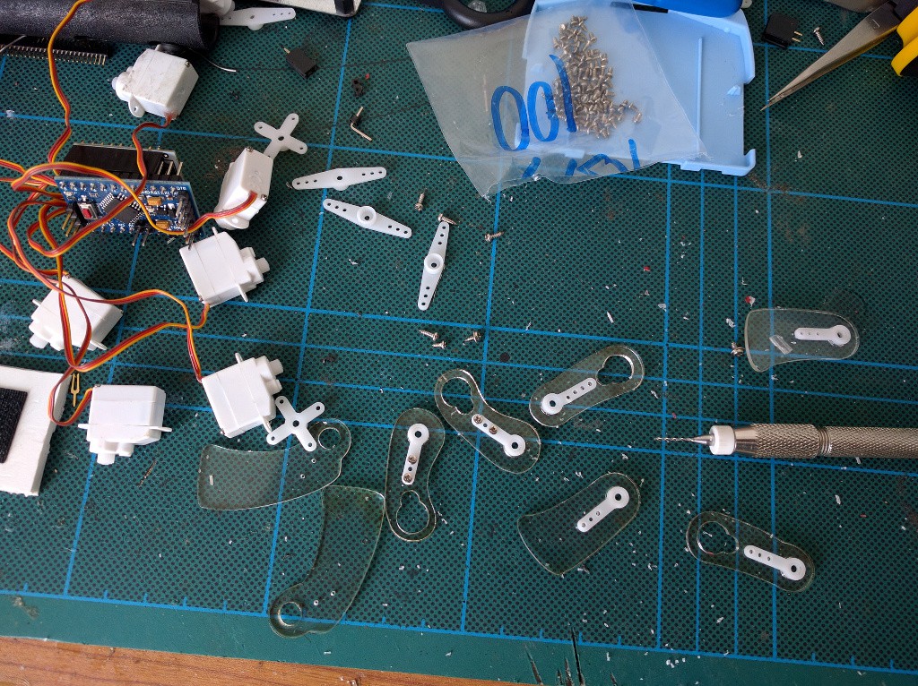
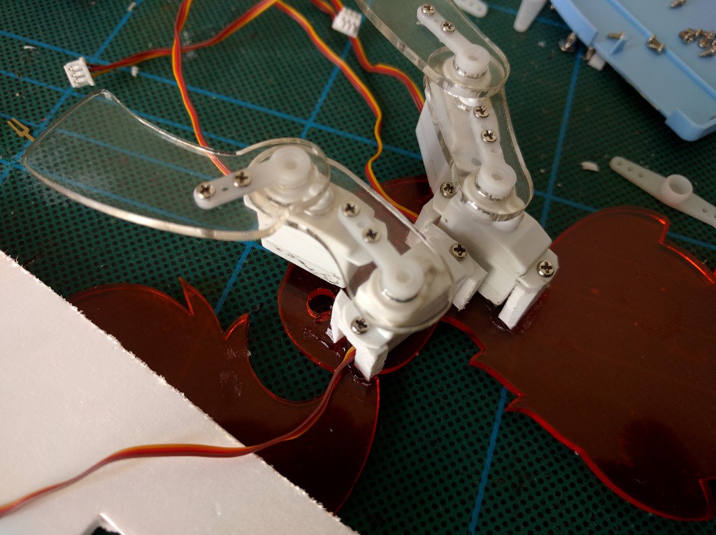
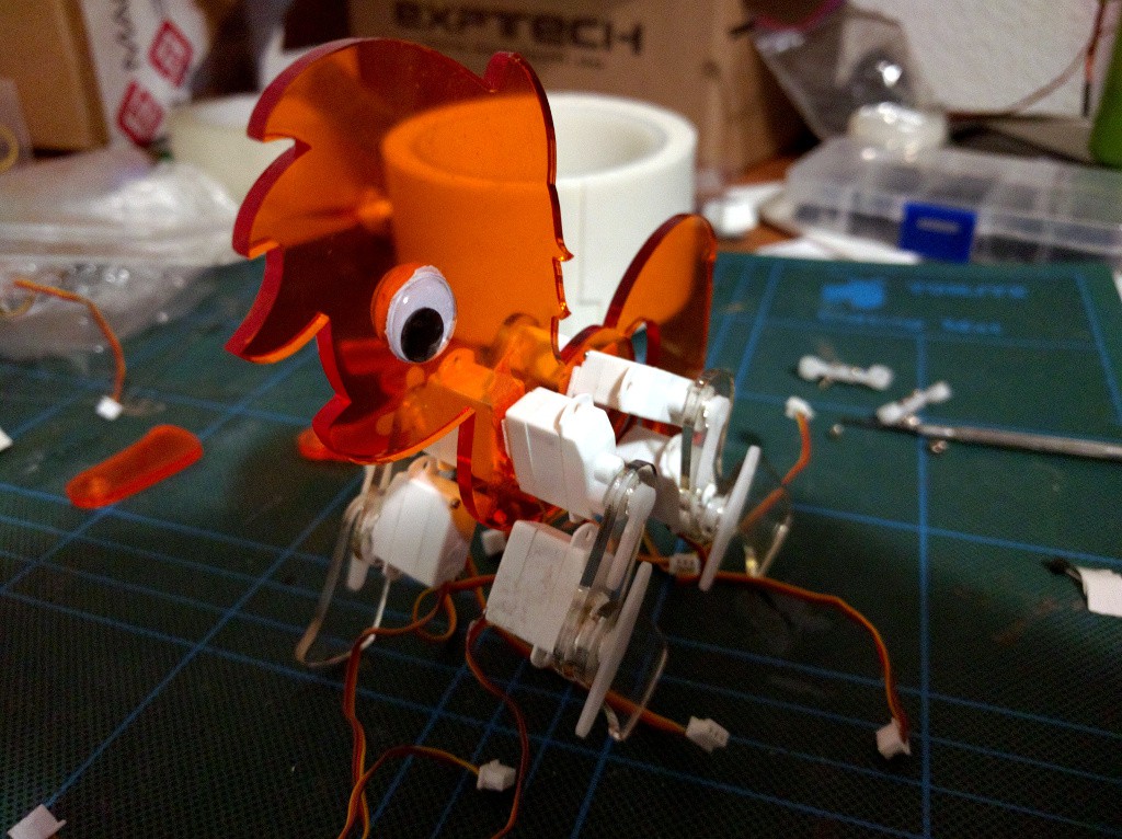
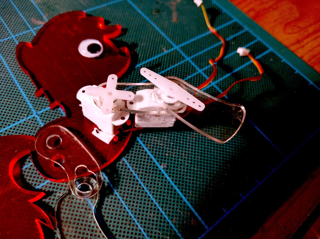
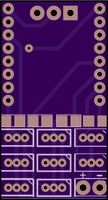
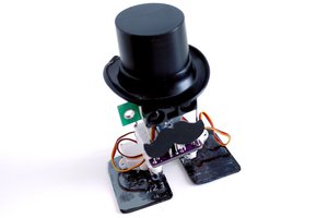
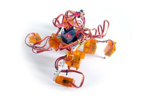
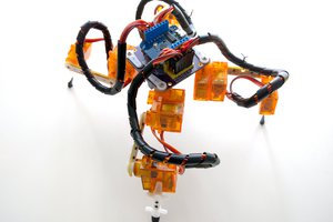
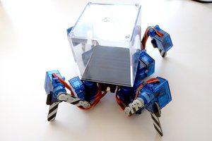
This is yet another attempt at a 8-servo walking robot, similar to #Katka and #µKatka. Except this time I want it to be a cute robot pet, so I had to choose a cute shape for it. I will need to make yet another breakout board for the servos (the one I used on µKatka has some flaws) and this time I will need some sensors -- not sure what yet.

svg+xml - 12.62 kB - 03/31/2016 at 18:59

Download

Adobe Portable Document Format - 4.48 kB - 03/31/2016 at 18:59

Preview
Download

  • Trinket M0

    deʃhipu09/19/2017 at 21:44 0 comments

    I recently dug out this robot for the maker faire (after seeing similar laser-cut ponies on the first day), and when I made the pwm shield for the Trinket M0, I decided that it would be the perfect brains. Using the ESP8266 alone with its 8 free pins all used for servos, with its software PWM kinda felt too hacky. I might still go back to an ESP87266 with a PCA9685 chip, we will see. For now, I'm using a Trinket M0 with a shield:

    I will also need to think a bit about cable management:

  • Better Servo Mounts

    deʃhipu09/19/2016 at 13:54 0 comments

    The new laser-cut body arrived, so I moved the servos to it. Among other things, it has the new servo mounting pieces that I came up with:

    The screw holes are a little bit hard to drill in the edge of the 2mm acrylic, and it's almost impossible to slide the servos on both sides in at once -- I will need to extend the slots to make it possible to slide them in place. Other than that, the whole thing looks much better:

    I now kinda regret putting that hole for the brains in the head, because it turns out that the board would fit between the servos on the body (and then the battery could go on the other side. I guess I will need one more prototype at some point. For now I want to get it to walk, though.

  • New Brain

    deʃhipu09/12/2016 at 20:07 0 comments

    Working on the code for walking, I managed to somehow damage the ESP-12 module I was using -- it would get in a boot loop, and refuse getting into the right boot mode even with the GPIO2 held down. After checking everything, I removed the board from the robot, checked everything once more, made a couple of measurements with the multimeter to make sure there are no shorts or breaks, and, running out of ideas, left it there for some time. Then I tried once more time, and it worked this time -- I could flash it again. However, I decided that I'm not going to rely on this module anymore (it's not an original one), and since the PCB I used had a number of mistakes that I had to work around, I decided to make a new board (I will still work on the program using the old one, while the new one is getting fabricated).

    So here it is:

    This time the PCB is exactly the same size as the ESP12 module. I managed to squeeze all the servo sockets and the resistors in there, and then decided to also add a voltage regulator (who knows, maybe the old module died because of wrong voltage) and some room for the power switch. Since there wasn't really any room for those, I put them under the wifi antenna of the module. Yes, I know that it will lower the range of the module and possibly introduce some interference. In the worst case I will redesign it again. The challenge was squeezing an additional power line in there (the servos still use the un-regulated power straight from the battery), but I managed to do it with just a couple of vias. The boards are ordered, should arrive in a couple of weeks.

    Once I had that done, I started to think about where it would be best to put that board on the pony itself. So far it has been strapped to the tail, because that was the largest free area, but it didn't look right. Finally, I decided to put the brain in the head, roughly in the same place where the real brain would be in a real pony. So I went to the design files, and made a hole in the head to hold that PCB. I also made some additional holes for the servo holders, and added the holders to the design file (with a hole in the middle for the wires):

    And I sent that to fabrication too. This time in a nice violet color, and in 2mm thick acrylic.

  • Some Code

    deʃhipu09/10/2016 at 12:33 0 comments

    I worked a little bit more on this robot today. Nothing exciting -- adjusted the servo angles in the inverse kinematics, upgraded to the newest version of MicroPython, recharged the dying battery, mapped the servos to the right joints on the right legs, etc. I also published the code and design files in a repository -- link on the left side, under the photos.

    This is really taking so much time mostly because I had so many other things to do in the mean time. Hopefully the robot will walk soon.

  • Schematic

    deʃhipu05/07/2016 at 12:46 0 comments

    I did some more assembling and programming, and I have a full control of all the eight servos now. With Python. Over w web-based console. How cool is that?

    Anyways, I realized that I never talked about the actual connections needed to get this to work, so let's talk about this for a moment. The ESP-12 module that I'm using has 11 GPIO pins available for use, not counting the pins broken out at the bottom of the module, which are used to communicate with the flash memory chip and shouldn't be touched. Micropython lets me do PWM output on 8 of those pins, because it assumes GPIO1 and GPIO3 are used for the serial, and GPIO16 is kinda special case in the code. That is quite lucky, because I need exactly 8 servos to make the pony walk.

    However, there is a small problem. Pins GPIO0, GPIO2 and GPIO15 are used to select the boot mode of the board. Connecting a servo to them makes them effectively pulled down -- which is fine for GPIO15, which I want pulled down, but not for GPIO0 and GPIO2, which I want pulled up. Fortunately, the servo will work quite fine with a signal that doesn't quite go all the way to 0, as long as it passes a certain threshold. So I determined experimentally, that pulling those two pins up with 10kΩ resistors makes them pulled up at boot, but still lets them drive the servos.

    The resulting schematic below:

    That still leaves the three GPIO pins and one ADC pin for my use. Since Micropython now has web-based REPL console, I can use the serial pins for other things. I would be most happy to use them for driving two of the servos, thus leaving the pulled-up GPIO0 and GPIO2 for I²C communication (they need to be pulled up for that anyways), alas, Micropython doesn't support PWM on those two pins. I also didn't find a way to disable the serial output on the TX pin, so for now the plan is to use the RX and GPIO16 pins for I²C communication with the sensors, and leave the TX pin for debugging. The ADC pin will probably be connected to a voltage divider to monitor the battery voltage.

  • Brains

    deʃhipu05/05/2016 at 22:02 0 comments

    The PCBs finally arrived, of course while I was travelling. I'm finally back, and I assembled the PCB. Of course, since they were designed in a hurry, there is a number of mistakes.

    • somehow I managed to swap the RST and ADC pins with TX and RX,
    • there is a short circuit right next to the battery connector,
    • I didn't leave any room for I²C pullup resistors,
    • I forgot to add room for the power switch.

    The short circuit was fixed with an x-acto knife. I'm not really using the RST and ADC pins, so I left them unconnected. For the serial connection, I also left the pins unconnected and soldered wires directly to the pads on the module. The power switch for now is on the battery cable, and I will see about the pullup resistors later. So I got the board working.

    Next, I flashed Micropython on the ESP8266 and did a quick test to see if the PWM signal for the servos works on all the pins -- including the ones that are pulled up or down for the board to boot in the right mode. For once it all worked great -- so that's one stone off my heart.

    Next, I'm going to make a nice servo library for the Micropython on ESP8266 (using the available PWM class, just wrapping it a bit for convenience) and see if I can get the gesture/distance sensors to work.

  • Servos, Horns and Screws

    deʃhipu04/14/2016 at 18:40 0 comments

    I'm taking this slow, figuring things as I go. Since my other projects went bad recently (I literally fried a PCB in one, and the other is drowned in instant glue), I decided to do anything with this one. So I went and screwed the servo horns to the legs properly:

    As a side note, I really love this drill handle I got at some RC model fair. It's perfect for making small, precise holes in delicate things, where a dremel wouldn't work so well. So some drilling and some M1.5x3 screws, and the horns are all properly attached.

    Next, I figured a way to attach the servos. I have some of those foamed plastic sheets, and they are perfect for prototyping -- soft enough to cut with a knife, but sturdy enough to build something out of them. I initially wanted to make the whole robot from it (like I did with #µKatka), but I wasn't sure what plastic it is exactly and if I can safely put that into the laser cutter, without damaging the lens with the fumes. Anyways, I cut some squares of that, cut an additional hole for the cable in them, and glued them to the body with instant glue. Then I simply used the screws that came with the servos to attach them to that. Looks better than I anticipated:

    One mistake I made, and I'm going to correct that in the "clean" version -- I put the servos too high. But that should be fine for testing.

  • Attaching Servos to the Body

    deʃhipu04/14/2016 at 08:17 4 comments

    So while I'm waiting for the PCB, I mock-assembled the remaining legs and started to do mockups with two-sided tape...

    I'm still trying to find a good way of attaching those servos to the body of the pony. Two-sided tape is obviously not the answer. Gluing them there is sub-optimal, as I might need to replace them. I don't have screws long enough to catch the servo ears and reach the body.

    My current thinking is gluing some additional ears to the servos, near the bottom, and then attaching those to the body with screws.

  • New Legs

    deʃhipu04/07/2016 at 17:55 0 comments

    I still got some time today to quickly bike to the FabLab and cut the new legs. I didn't have orange acrylic that thin, though, so they are transparent for the prototype. The final version can of course be anything, maybe I will go for glow-in-the-dark, even!

    As you can see, the new version fits perfectly -- the servos just snap in and hold tight. I used some dirty broken ones and random horns here, just to see if the fit.

    The PCB should arrive within 2 weeks, I can continue with it then.

  • Controller PCB

    deʃhipu04/06/2016 at 08:55 0 comments

    While I wait to cut the new legs, I also prepared a new PCB for the controller. I plan to use an ESP-12 module with Micropython on it to control the eight servos, but I can't use the same board I had in #µKatka, because Micropython allows PWM on different pins. So I went and made a quick breakout board again, this time with plenty pull-up and pull-down resistors, so that I can also use those pins that normally select the boot mode:

    As you can probably guess from the color, the PCB is ordered from OSHPark -- I prefer it for the boards smaller than 5×5cm, even though the shipping from US takes ages. The connections are nothing special -- all the servos are connected to all the PWM-capable pins, serial and ground are available at the top, and power is at the bottom. I used holes instead of pads for attaching the ESP-12 module, because that is easier to solder. The antenna will stick out at the top. The four SMD resistors provide pull-ups for CH_EN, GPIO0 and GPIO2, and a pull-down for GPIO15. I will need to pick the values of the resistors such that they work well with the servos connected to those pins (well, except for CH_PD). I have the ADC and the serial pins available, so I will probably use them for some sensors -- not sure what exactly yet.

View all 12 project logs

Enjoy this project?

Share

Discussions

Sam P wrote 04/01/2016 at 12:06 point

Awesome project! It reminds me of this pony robot:

  Are you sure? yes | no

deʃhipu wrote 04/01/2016 at 12:11 point

Wow, that is taking this much further than I ever expected to go. Really awesome!

I will be happy if I get it to walk and do some simple tricks.

  Are you sure? yes | no

DJ-TrainR3k wrote 04/05/2016 at 12:02 point

I was actually thinking of making the same type of Sweetie Bot robot a few months ago... Think I might still design/prototype/make one as a challenge though.

  Are you sure? yes | no

deʃhipu wrote 04/05/2016 at 13:41 point

Let me know if you have problems getting it to walk! I'd love to help!

  Are you sure? yes | no

RoGeorge wrote 09/21/2017 at 06:34 point

Nice robot in the video, but that head is too close to the uncanny valley. Creepy!

  Are you sure? yes | no

danjovic wrote 04/01/2016 at 01:03 point

Cute project, Radomir!

  Are you sure? yes | no

deʃhipu wrote 04/01/2016 at 08:02 point

Thanks. It will be less cute with all the electronics strapped on it, but hopefully some of the cuteness will remain.

  Are you sure? yes | no

Similar Projects

Does this project spark your interest?

Become a member to follow this project and never miss any updates